2000 Ford Ranger Brake Line Diagram 2026: Proper Routing

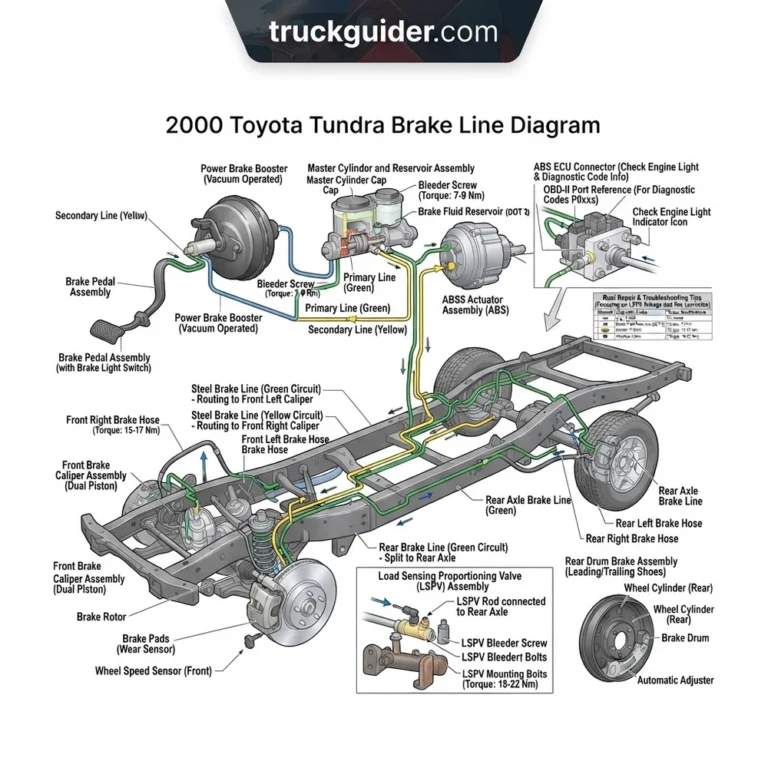
The 2000 ford ranger brake line diagram shows component layout, connection points, and routing paths. Use it to identify parts, diagnose issues, and follow correct installation or repair procedures.
📌 Key Takeaways
- Understanding the 2000 ford ranger brake line diagram is essential for proper implementation
- Each component has a specific role and connection point
- Following safety guidelines prevents common mistakes
- This diagram serves as a reference for practical applications
- Regular review helps maintain accurate understanding
The 2000 Ford Ranger utilizes a split hydraulic brake circuit designed to provide reliable stopping power across diverse payload conditions. Depending on whether your chassis is equipped with Rear-Wheel Anti-Lock Brakes (RABS) or full 4-Wheel Anti-Lock Brakes (4WABS), the routing, valving, and port configurations vary significantly. Understanding the factory hydraulic line paths, fitting specifications, and chassis mounting points is vital when diagnosing fluid leaks, replacing corroded steel lines, or executing a hydraulic overhaul. This guide provides an exhaustive engineering breakdown of the 2000 Ford Ranger brake line diagram, plumbing schematics, torque specifications, and system diagnostics.
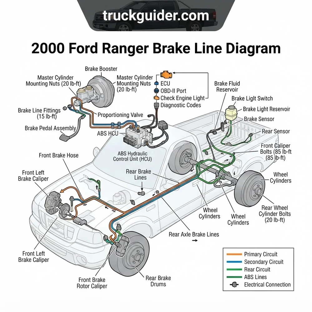
2000 Ford Ranger Brake Line Diagram: Hydraulic Component Layout


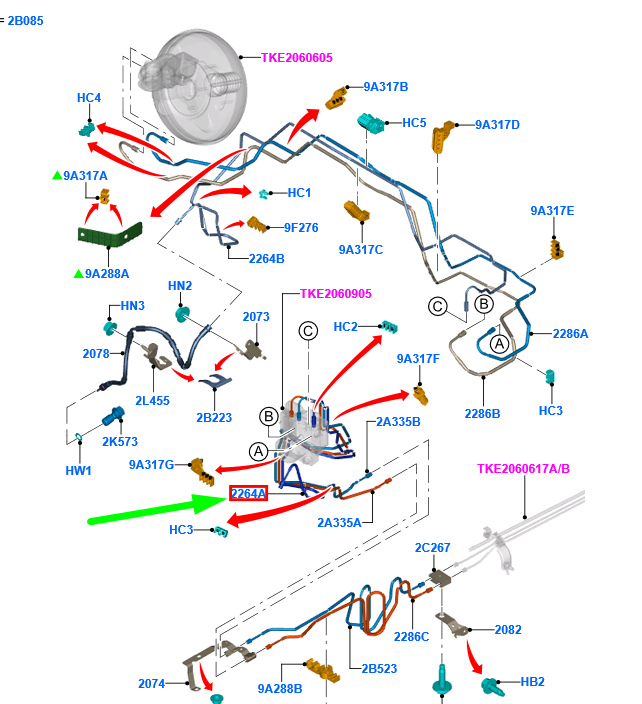
The primary hydraulic circuit originates at the brake master cylinder mounted to the vacuum brake booster on the driver-side firewall. The master cylinder features a dual-reservoir, tandem-bore configuration that isolates the primary and secondary hydraulic circuits. This design ensures partial braking capacity remains if one circuit experiences a pressure drop or line rupture. Fluid exits the master cylinder via two side-facing outlet ports, feeding pressurized DOT 3 fluid downstream into the anti-lock brake module before distributing to individual wheel assemblies.
On vehicles equipped with 4-Wheel ABS (4WABS), both primary and secondary hard lines drop downward from the master cylinder along the inner fender apron to the ABS Hydraulic Control Unit (HCU). The HCU contains an integrated electric motor, internal accumulator chambers, and solenoid valves managed by an electronic control module. The HCU processes hydraulic pressure and modulates fluid volume via three or four delivery circuits: independent feeds for the left front and right front calipers, and a combined or split intermediate feed running rearward to the rear drums.
The front brake lines transition from rigid steel tubing to reinforced flexible rubber hoses at the frame brackets located behind each front shock tower. The front hard lines follow the contours of the front crossmember beneath the engine oil pan. Fluid traverses the vehicle’s centerline via this crossmember tube, terminating at the passenger-side junction bracket. From the bracket, high-pressure flexible hoses bridge the dynamic gap between the rigid chassis and the floating single-piston front brake calipers mounted to the steering knuckles.
The rear hydraulic circuit travels down the inside driver-side frame rail. A single intermediate steel line runs from the front hydraulic module back toward the rear axle, routed inboard of the frame rail channel to shield it from road debris. Forward of the rear axle housing, this hard line terminates at a chassis-mounted junction bracket. A flexible center brake hose drops downward from the frame crossmember to a distribution block (junction tee) integrated into the rear axle breather vent fitting on the driver-side axle tube. Two rigid axle lines branch outward from this junction tee, tracing the axle housing tubes to deliver hydraulic pressure to the left and right rear drum brake wheel cylinders.
| Component | Port Configuration & Thread Size | Hydraulic Operating Function | Chassis Location |
|---|---|---|---|
| Master Cylinder | Primary: 7/16-24 Inverted Flare; Secondary: 3/8-24 Inverted Flare | Converts mechanical pedal effort into hydraulic line pressure | Driver-side firewall, affixed to vacuum booster |
| ABS Hydraulic Control Unit (HCU) | Inlets: M10x1.0 / M12x1.0; Outlets: 3/8-24 & 7/16-24 (varies by ABS trim) | Modulates brake fluid pressure during wheel lockup events | Driver-side lower engine bay, below master cylinder |
| Front Crossmember Hard Line | 3/16″ Tubing with 3/8-24 Inverted Flare Nuts | Routes hydraulic pressure across frame to passenger caliper | Tucked within the front engine subframe crossmember |
| Front Flexible Caliper Hoses | Inlet: 3/8-24 Female; Caliper: 10mm (3/8″) Banjo Fitting | Accommodates steering sweep and suspension articulation | Inner fender wall to front floating brake calipers |
| Intermediate Rear Hard Line | 3/16″ Tubing, 3/8-24 Inverted Flare (Chassis fittings) | Main hydraulic delivery line feeding the entire rear braking system | Inner channel of left frame rail, inboard of fuel tank |
| Rear Axle Junction Hose & Tee | Inlet: 3/8-24 Female; Outlets: 3/8-24 Inverted Flare Ports | Splits intermediate pressure between left and right wheel cylinders | Mounted atop differential housing via axle vent tube bolt |
| Rear Wheel Cylinders | 3/8-24 Inverted Flare Inlet Port | Actuates leading and trailing drum brake friction shoes | Upper mounting bore on rear brake backing plates |
When servicing the master cylinder, bench bleeding is mandatory prior to connecting vehicle lines. Entrained air in the master cylinder secondary bore cannot be easily purged through the ABS module using standard pedal bleeding methods.
RABS vs 4WABS Routing Schematics, Tube Diameters, and Torque Specs



The 2000 Ford Ranger was manufactured with two distinct hydraulic control architectures: Rear-Wheel ABS (RABS II) and 4-Wheel ABS (4WABS). RABS configurations manage lockup only on the rear axle using an electro-hydraulic proportioning and dump valve mounted to the inner frame rail below the driver’s floorpan. In contrast, 4WABS configurations utilize a comprehensive HCU located under the hood that individually pulses front wheels while simultaneously managing the rear circuit. Identifying your specific ABS option is critical for reading the 2000 Ford Ranger brake line diagram correctly.
In RABS-equipped Rangers, the primary port of the master cylinder feeds directly into a chassis-mounted combination/proportioning valve, which then splits directly to the two front wheels. The secondary port routes into the RABS hydraulic valve on the frame rail before traveling the length of the chassis to the rear drums. In 4WABS setups, no external chassis-mounted RABS valve exists; both primary and secondary circuits enter the HCU block directly, and individual output lines exit the module.
Ford utilized standard SAE double flares (45-degree inverted flare) for the majority of the chassis line junctions on the 2000 Ranger, although metric bubble flares (ISO/DIN) are present on select ports of the Kelsey-Hayes 4WABS control module. The standard tubing outer diameter (OD) throughout the chassis is 3/16-inch (4.75mm) with standard 3/8-24 threaded tube nuts. However, specific ports at the master cylinder and ABS block use oversized tube nuts (such as 7/16-24 or 1/2-20 threads) to prevent line cross-threading during factory assembly.
| Feature / Specification | Rear-Wheel ABS (RABS II) | 4-Wheel ABS (4WABS) |
|---|---|---|
| ABS Valve Location | Driver inner frame rail beneath cab floor | Engine bay, driver inner fender below master cylinder |
| Front Circuit Routing | Master cylinder to front proportioning tee to calipers | Master cylinder to HCU to individual LF and RF flex lines |
| Rear Intermediate Line Routing | Exits frame-mounted RABS valve directly to rear axle | Exits HCU in engine bay, follows frame rail to rear axle |
| Line Tubing Size (Chassis) | 3/16″ (4.75mm) OD hard line throughout | 3/16″ (4.75mm) OD; select primary feeds use 1/4″ (6.35mm) |
| Standard Tube Nut Torque Spec | 13–17 N·m (10–13 lb-ft / 120–150 lb-in) | 13–17 N·m (10–13 lb-ft / 120–150 lb-in) |
| Front Caliper Banjo Bolt Torque Spec | 40–45 N·m (30–33 lb-ft) with copper crush washers | 40–45 N·m (30–33 lb-ft) with copper crush washers |
| Rear Wheel Cylinder Fitting Torque | 11–14 N·m (8–10 lb-ft / 97–124 lb-in) | 11–14 N·m (8–10 lb-ft / 97–124 lb-in) |
| Bleeder Screw Torque Spec | 8–11 N·m (71–97 lb-in) | 8–11 N·m (71–97 lb-in) |
Factory hard lines rely on SAE 45-degree inverted double flares. Never mate an ISO bubble flare line to an SAE inverted flare seat or vice versa; the mismatch in sealing angle causes fluid bypass under high hydraulic line pressure (exceeding 1,200 PSI during panic stops).
Brake Line Failure Symptoms and Frame Rail Rust Locations
The 2000 Ranger chassis is notoriously prone to localized corrosion that compromises brake line integrity. Because original factory lines were constructed of standard coated low-carbon brazed steel, exposure to environmental road salts and road grime causes severe oxidation. Degradation occurs in specific trap zones where moisture cannot evaporate naturally.
The primary failure points and warning symptoms include the following structural areas:
- Fuel Tank Frame Rail Pocket: The single most common point of hydraulic failure on the 2000 Ford Ranger is the section of the intermediate rear hard line hidden between the driver-side frame rail and the plastic fuel tank. Road debris, mud, and road brine settle into the small gap between the frame channel and the tank mounting straps. Because this area is shielded from chassis wash-offs, the steel line corrodes completely through, resulting in sudden, catastrophic fluid loss when pressing the brake pedal.
- Front Engine Crossmember Cradle: The crossover line feeding the right-front brake caliper runs inside the lower front crossmember. This channel sits directly beneath the engine accessory drive and radiator coolant flow hoses. If coolant seeps from cooling components or engine oil drops from the oil pressure sending unit onto this line, moisture and acidic buildup collect in the crossmember channel, creating invisible pinholes along the bottom run of the pipe.
- Rear Axle Vent Tee Junction: The rear axle distribution block incorporates the rear axle housing breather. Road grit accumulates around this junction, corroding the hard lines right at the tube nuts where they enter the distribution tee. Corrosion here also frequently causes the bleeder screws on the rear wheel cylinder assemblies to seize solid into the backing plate casting.
- Soft or Sinking Brake Pedal: A pinhole leak anywhere along the hydraulic lines introduces compliance into the system. As line pressure rises, fluid sprays outward, causing the brake pedal to travel completely to the floorboards. In dual-circuit configurations, a blown rear line drops the pedal roughly 70% toward the floor before the primary front circuit establishes mechanical resistance.
- Dashboard Warning Illuminations: Fluid loss triggers the mechanical differential pressure switch inside the master cylinder or proportioning valve, illuminating the red “BRAKE” dash warning light. While powertrain faults like timing chain slack or secondary air injection failures activate the yellow check engine light via the main ECU, brake circuit pressure differentials trigger the instrument cluster directly. Scanning the vehicle via an OBD-II interface capable of reading chassis modules will often reveal an ABS diagnostic code corresponding to pump motor circuit performance (such as code C1095) or wheel speed sensor inconsistencies caused by uneven braking forces.
- Fluid Weepage at Flex Hose Crimps: The front flexible brake hoses and rear drop hose experience continuous flexing and chassis movement. Over time, moisture causes internal rust at the steel crimp collars where the rubber hose joins the metal fitting. This pinches the internal Teflon/EPDM liner, acting as a one-way check valve that traps line pressure and causes front brake calipers to drag, overheat, and glaze the friction pads.
If the brake pedal exhibits a sudden increase in travel accompanied by a red instrument cluster warning, do not drive the vehicle. Operating a Ranger with a compromised hydraulic circuit overworks the remaining axle circuit and dramatically increases stopping distances.
How to Trace and Inspect the 2000 Ford Ranger Brake Line Diagram
Diagnosing suspected hydraulic leaks, pinholes, or line blockages requires a methodical tracing process starting from the highest point in the system down to the friction hardware. Follow this diagnostic inspection workflow:
- Perform a Static Master Cylinder and Bulkhead Inspection: Inspect the master cylinder fluid level in both reservoir chambers. Check the underside of the master cylinder body where it bolts to the vacuum booster; a failing rear piston seal will leak fluid directly into the booster shell. Inspect the two primary output tube nuts using a flare nut wrench to verify they are seated without fluid weeping at the threads.
- Trace Downstream to the HCU / RABS Module: Follow the two hard lines down the driver’s side inner wheel well to the ABS HCU (on 4WABS) or frame-mounted RABS valve. Inspect all inlet and outlet tube nuts for signs of dampness or mineral crusting. Ensure wire harnesses connecting the ABS module to the chassis harness are dry; brake fluid is conductive and corrosive to electrical terminals.
- Inspect the Front Crossmember and Wheel Well Transitions: Follow the front left line to the inner frame bracket. Inspect the union between the hard line and flexible hose. Trace the passenger-side front hard line across the front chassis subframe crossmember, inspecting the retaining clips that isolate the line from engine vibrations. Verify that the line does not contact the oil filter adapter or engine oil pressure sender housing.
- Trace the Driver Frame Rail Intermediate Line: Elevate the vehicle safely on jack stands or a chassis lift. Using an inspection light and an automotive inspection mirror, examine the intermediate hard line running inside the frame channel. Pay specific attention to the line clips located between the frame rail and the fuel tank. Look for bubbling paint, flaking rust scales, or dark fluid staining along the bottom edge of the frame channel.
- Evaluate the Rear Axle Drop Hose and Hard Axle Tubing: Trace the line to the rear frame crossmember forward of the differential. Inspect the rubber center drop hose for dry rot, cracking, or outer jacket ballooning under pedal pressure. Inspect the junction tee mounted to the axle tube vent and follow the two rigid lines across the axle housing to the left and right wheel cylinder backing plates.
- Perform Hydraulic Pressure Verification: With the engine running (to provide vacuum assist), have an assistant exert firm, steady pressure on the brake pedal while you inspect every flare connection and frame clamp. A pinhole leak that appears dry under static conditions will spray a fine jet of DOT 3 fluid under full line pressure (800–1,200 PSI). Check that the flexible rubber hoses do not expand or bulge outward along their outer casing under sustained hydraulic force.
Replacing 2000 Ford Ranger Brake Lines: Routing and Bleeding Rules
Replacing damaged lines on a 2000 Ford Ranger requires routing replacement lines away from abrasion sources and executing a proper hydraulic purge. While factory replacements were pre-bent coated steel, modern best practice utilizes Copper-Nickel alloy tubing (commonly known as NiCopp or CuNi 90-10). NiCopp lines do not rust, bend easily by hand without kinking, and seat exceptionally well into inverted flare ports without galling the threads.
When running the replacement intermediate line along the frame rail, you do not need to drop the fuel tank completely if you use bulk coil tubing. Unbolt the front and rear fuel tank strap bolts to lower the tank roughly 3 to 4 inches, supporting it safely with a transmission jack. This provides sufficient clearance to slide the new 3/16-inch tubing through the original factory plastic retention clips along the inside C-channel of the frame. Ensure the replacement line maintains at least 2 inches of clearance from the exhaust system and does not rub against the cab mount brackets.
When forming flares, cut the tubing squarely with a dedicated tubing cutter and thoroughly deburr the inside and outside edges of the pipe. Chamfering the tube mouth is essential to ensure the SAE 45-degree inverted double flare folds inward symmetrically without cracking the tube shoulder. Always slip your tube nut onto the line before performing the double flare operation.
After mechanical installation is complete, you must bleed the entire hydraulic system. The standard manual bleeding sequence for the 2000 Ford Ranger proceeds in order of hydraulic distance from the master cylinder: Right Rear (RR), Left Rear (LR), Right Front (RF), and Left Front (LF).
If the master cylinder or ABS HCU ran dry during the line failure or replacement process, air will be trapped inside the internal valve seats of the ABS block. A standard manual two-person bleed will not dislodge air bubbles trapped in the ABS accumulator chambers. You must connect an OBD-II diagnostic tool capable of bi-directional control to initiate an “ABS Automated Bleed” cycle. The scan tool commands the ABS module to cycle its internal solenoid valves and spin the return pump motor for approximately 60 seconds while you hold down the brake pedal, forcing trapped air down into the intermediate lines where it can be bled out via standard wheel cylinder and caliper bleeder screws.
Only use clean Motorcraft High Performance DOT 3 brake fluid or equivalent meeting Ford specification ESA-M6C25-A. Never use DOT 5 silicone fluid, as it is completely incompatible with the EPDM rubber seals and internal valves inside the Kelsey-Hayes ABS module.
2000 Ford Ranger Brake Line Diagram Questions Answered
What size brake line tubing does a 2000 Ford Ranger use?
The vast majority of the 2000 Ford Ranger hydraulic system utilizes 3/16-inch (4.75mm) outer diameter (OD) tubing. This size is used for the front caliper feed lines, the intermediate chassis run to the rear axle, and the rear axle hard lines. On select 4WABS configurations, the primary feed lines running from the master cylinder down to the ABS Hydraulic Control Unit (HCU) inlet ports utilize 1/4-inch (6.35mm) OD tubing to support high initial fluid volume delivery.
Can I bend and install pre-formed brake lines without dropping the fuel tank?
Rigid, pre-bent factory steel replacement lines cannot be installed along the driver-side frame rail without completely dropping the fuel tank and unbolting the transfer case skid plate (on 4×4 models). However, if you construct replacement lines using flexible Copper-Nickel (NiCopp) alloy tubing fed from a coil, you can carefully route the line through the factory frame channel clips by simply loosening the fuel tank straps and lowering the tank by a few inches.
Why is my brake pedal still spongy after bleeding every wheel caliper and cylinder?
If you have manually bled all four corners and the pedal remains spongy, air is trapped inside the ABS Hydraulic Control Unit (HCU). When air enters the HCU valve block, standard pedal pumping cannot create the velocity required to push bubbles past the spring-loaded internal accumulator and dump valves. You must use an OBD-II scan tool with bi-directional ABS bleed functionality to run an automated ABS service bleed routine, cycling the internal pump and solenoids.
What is the difference between the red BRAKE dash light and the check engine light?
The red “BRAKE” light on the instrument cluster is activated mechanically by a differential pressure switch located on the master cylinder or proportioning valve, indicating hydraulic line pressure loss or low fluid in the reservoir. In contrast, the yellow check engine light is illuminated by the powertrain ECU when an engine or emissions diagnostic code is logged (such as timing chain sensor faults, misfires, or cooling anomalies). ABS-specific electronic faults will illuminate the separate amber “ABS” dashboard light.
What type of flare does the 2000 Ford Ranger require for brake line unions?
The chassis junctions, wheel cylinders, caliper flex hose joints, and master cylinder ports on the 2000 Ford Ranger require standard SAE 45-degree inverted double flares. Do not use 37-degree AN flares or single flares. Single flares lack the double-wall structural strength needed to withstand extreme braking pressures and will crack at the tube neck under heavy pedal force.
Step-by-Step Guide to Understanding the 2000 Ford Ranger Brake Line Diagram
Identify the main components in the diagram
Locate connection points and relationships
Understand the flow or sequence shown
Apply the knowledge to your specific situation
Verify your understanding matches the diagram