2000 Toyota Tundra Fuse Box Diagram: 2026 Troubleshooting

The 2000 Toyota Tundra features two primary fuse blocks: the engine compartment junction block beside the driver-side battery housing high-amp fuses (100A ALT, 30A AM2) and EFI relays, and the interior fuse panel behind the lower driver-side kick panel covering OBD-II (7.5A OBD), ECU-IG (10A), and power accessories.
📌 Key Takeaways
- Under-hood main fuse box houses primary relays: EFI (20A), starter (STA 7.5A), and ALT fusible link (100A/120A).
- Cabin panel is situated behind the coin pocket pull-out on the driver-side lower dashboard instrument panel.
- Battery terminal clamping bolt requires a torque spec of 48 in-lbs (5.4 Nm) to prevent voltage drop issues.
- A blown 15A EFI or 7.5A OBD fuse disrupts scanner communication and illuminates the check engine light.
- Replace standard fuses yourself, but seek professional diagnosis if fusible links melt repeatedly or bus bars corrode.
The 2000 Toyota Tundra relies on a centralized electrical distribution network engineered to support both the base 3.4-liter 5VZ-FE V6 and the robust 4.7-liter 2UZ-FE V8 platforms. Navigating electrical faults in this first-generation pickup requires an exact understanding of fuse assignments, wire color codes, load ratings, and relay bus architectures. When troubleshooting dead instrument clusters, fuel delivery dropouts, or communication failures at the data link connector, relying on a verified electrical map is essential.
This comprehensive technical guide details the under-hood power distribution center, the in-cabin junction block, and related sub-relays. By cross-referencing your truck’s factory ratings with the schematics below, professional technicians and advanced DIYers can rapidly isolate open circuits, high-resistance faults, and shorted harnesses across the entire truck platform.
—
2000 Toyota Tundra Fuse Box Diagram and Panel Locations
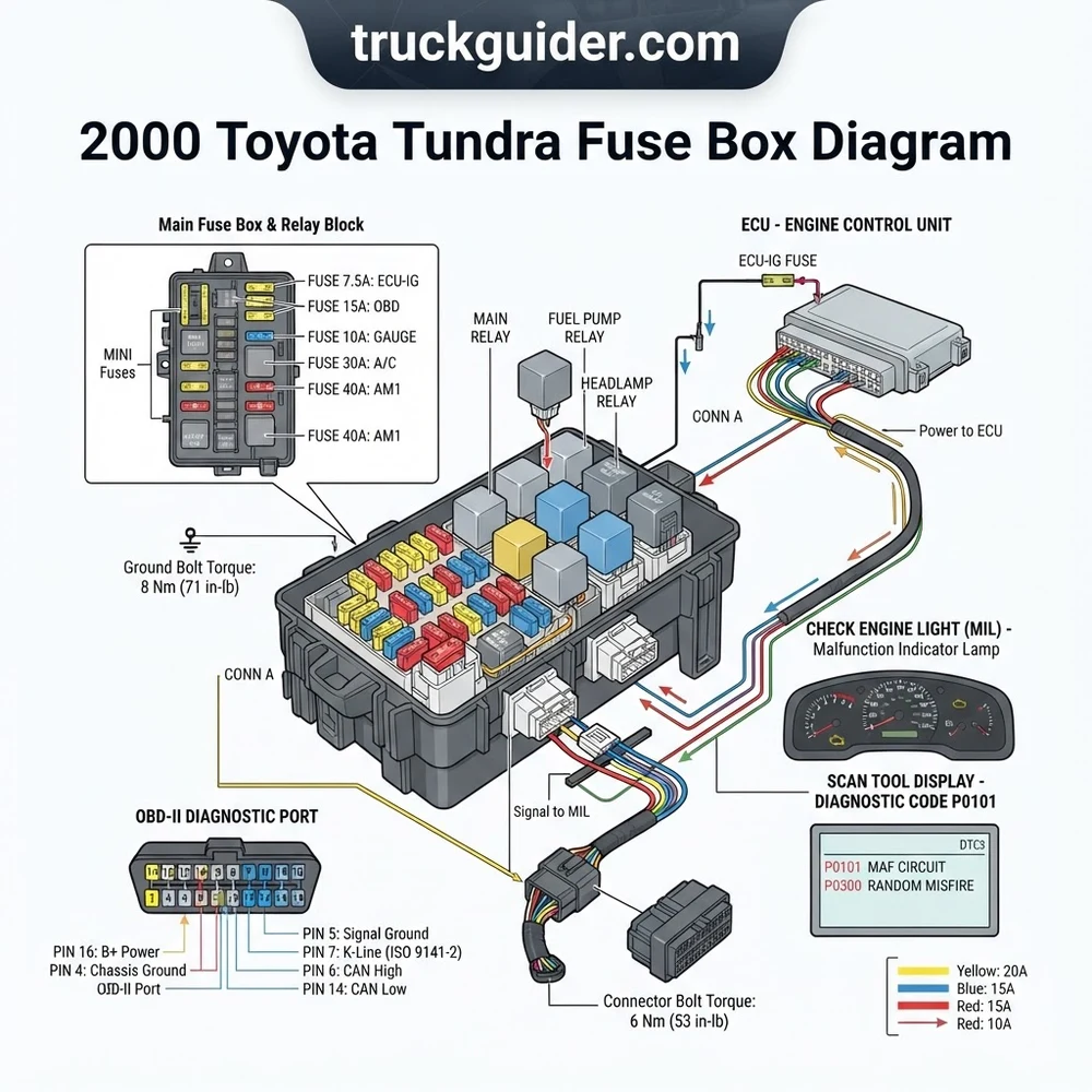
Locating the circuit protection hardware on the 2000 Toyota Tundra requires accessing two primary junction enclosures: the engine compartment power distribution block and the lower passenger-cabin instrument panel fuse board.
Engine Compartment Fuse Block
The under-hood electrical distribution box is mounted on the driver-side inner fender apron, positioned directly between the 12V starting battery and the brake master cylinder fluid reservoir. Enclosed in a high-impact, weather-sealed polypropylene housing, this block houses the high-amperage fusible links, electromechanical engine-control relays, and primary system branch fuses.
To access the panel, release the retaining clip located on the outboard edge of the housing and pivot the lid upward. Molded directly into the underside of this lid is an embossed schematic detailing fuse nomenclature, ampere ratings, and physical orientations. A specialized white nylon fuse puller tool is clipped into a dedicated storage dock within this box, specifically sized to grasp low-profile mini-blade fuses without damaging surrounding plastic walls.
Interior Instrument Panel Fuse Box
The interior cabin junction box is situated on the lower driver-side dashboard assembly. It is positioned behind the coin tray/pull-down dashboard pocket, adjacent to the emergency parking brake pedal mechanism and the primary cowl side trim kick panel.
To reach these circuits:
1. Pull the dashboard pocket outward until it meets its primary travel stop.
2. Squeeze both side tabs inward to disengage the retaining stops.
3. Tilt the assembly downward and pull toward the seat floor to unhook the hinge pivots.
The exposed multi-fuse array positions branch circuits directly beneath the main dashboard wiring harness. A label decal fixed to the backside of the removed pocket provides an indexed map identifying each mini blade fuse by acronym and amperage. For related body electrical repair, consult our comprehensive guide on first-generation Toyota truck instrument cluster wiring schematics.
—
2000 Tundra Fuse Block Component Identification and Amps
The 2000 Toyota Tundra utilizes standard low-profile mini blade fuses (type ATM), cartridge-style JCASE fuses, and bolted high-ampere multi-fusible links. The tables below outline factory circuit designations, nominal current limits, wire-protected loads, and corresponding equipment operations for trucks equipped with the 4.7L 2UZ-FE V8 or 3.4L 5VZ-FE engines.
Engine Compartment Power Distribution Center
| Designation | Amp Rating | Protected Circuit / Load Assignment |
|---|---|---|
| ALT | 100A / 140A | Charging system, alternator B+ feed, cabin bus main rail |
| MAIN | 40A | Primary ignition switch input, starter relay coil, AM1 feed |
| AM2 | 30A | Ignition switch contacts, fuel injection system, IGN fuse |
| HEATER | 50A | HVAC blower motor resistor and front blower motor relay |
| ABS 1 | 60A | Anti-lock Brake System hydraulic pump motor actuator |
| ABS 2 | 30A | Anti-lock Brake System solenoid valve assembly |
| EFI | 20A | Engine Control Module (ECU), mass air flow sensor, fuel pump |
| H-LP RH | 15A | Right high/low beam headlamp bulb filament |
| H-LP LH | 15A | Left high/low beam headlamp bulb filament, high-beam indicator |
| TOWING | 30A | Trailer tow package connector, electric trailer brake feed |
| HAZARD | 15A | Turn signal flasher relay, hazard warning switches |
| HORN | 10A | Dual front horn assembly, horn relay contact terminal |
| A/C MAG | 10A | Air conditioning compressor magnetic clutch solenoid |
| FOG | 15A | Front bumper lower auxiliary fog lamps |
Passenger Compartment Instrument Panel Fuse Box
| Designation | Amp Rating | Protected Circuit / Load Assignment |
|---|---|---|
| CIG | 15A | Center console cigarette lighter socket, power mirror remote |
| IGN | 10A | SRS Airbag control module, fuel pump relay driver circuit |
| TAIL | 15A | Running lights, license plate lamps, instrument illumination |
| STOP | 15A | Stop lamp switch, high-mount 3rd brake light, ABS sensor input |
| OBD | 7.5A | OBD-II Data Link Connector 3 (Pin 16 battery feed) |
| ECU-IG | 10A | Cruise control actuator, shift lock control, ABS ECU key-on |
| ECU-B | 7.5A | Body Control Module memory, multiplex network transceivers |
| DOME | 15A | Interior dome light, map lights, door courtesy lamps, clock |
| WIPER | 20A | Windshield wiper motor, intermittent pulse relay, washer pump |
| GAUGE | 10A | Speedometer, tachometer, oil pressure gauge, charging indicator |
| POWER | 30A | Power window master switch, power door lock actuators |
| DEFOG | 20A | Heated exterior rear-view side mirrors (cold-spec trim) |
On the 2000 Tundra with the 4.7L 2UZ-FE V8, the 20A EFI fuse supplies direct unswitched battery voltage to the contacts of the EFI Main Relay. When the powertrain ECU pulls terminal MREL to ground, current drives downstream into the individual ignition coils and fuel injectors. A hairline fatigue crack in this single mini blade fuse results in an immediate crank-no-start condition with zero fuel delivery.
—
Blown Fuses, Dead OBD-II Ports, and Check Engine Light Symptoms
Electrical malfunctions on the 2000 Tundra frequently originate from predictable stress points in the body wiring. By pairing physical operating symptoms with specific fuse networks, you can cut diagnosis time significantly:
Completely Dead OBD-II Port (Scanner Fails to Power On): The diagnostic link connector (DLC3) located under the lower dashboard steering knee bolster uses Pin 16 to feed unswitched 12V power to scan tools. Pin 16 is protected directly by the 7.5A OBD fuse located in the interior junction box. In earlier production 2000 models, this circuit shares trace paths with the 15A DOME fuse. If a generic scan tool refuses to power up to scan a diagnostic code, verify whether the overhead dome lights illuminate. If both systems fail, replace the DOME or OBD fuse and inspect the vanity mirror wiring harnesses for a grounded short circuit.
Engine Cranks Indefinitely with Check Engine Light Inoperative: Under normal operation, turning the ignition key to the “ON” position triggers a bulb check where the check engine light illuminates on the cluster. If the lamp fails to illuminate and the engine refuses to start, the powertrain ECU is not receiving system power. Trace the 20A EFI fuse and the 10A IGN fuse. In many instances, the wire loom leading to the post-catalytic bank oxygen sensor heats up, melts on the exhaust crossover pipe, and shorts the 12V heater circuit to chassis ground, instantly vaporizing the 20A EFI fuse.
Inoperative Tail Lights Combined with Instrument Cluster Darkening: The 15A TAIL fuse protects both the exterior parking lamps and the instrument cluster dimmer circuit. A common failure point on first-generation Tundras involves aftermarket or factory trailer hitch tow plugs. Moisture, road salts, and mechanical crushing of the 4-pin or 7-pin trailer connector cause cross-pin shorts between ground and the tail marker wire, immediately opening the 15A TAIL fuse whenever the headlight switch is rotated to position 1.
Intermittent Starter Click with Fully Charged 12V Starting Battery: If battery terminal voltage confirms 12.6V or greater under load, but turning the key produces only an isolated single relay tick, investigate the 40A MAIN fuse and the STARTER relay terminals in the under-hood block. Oxidation along the starter solenoid signal spade terminal under the intake manifold causes excessive resistance, over-drawing the low-voltage control loop.
For advanced diagnostic strategies on electronic engine controls, see our complete guide to Toyota 2UZ-FE timing belt and water pump overhaul procedures to ensure mechanical timing remains in spec during deep no-start evaluations.
—
Diagnosing Circuit Failures with the 2000 Tundra Diagram
Isolating blown fuses without introducing intermittent secondary electrical faults requires a systematic diagnostic sequence. Avoid arbitrary fuse pulling, which can clear stored volatile ECM shift adapts and set false diagnostic trouble codes.
1. Isolate the Non-Functional Subsystem
Identify all non-functional accessories on the truck. If only the 12V utility power socket is dead, focus exclusively on the 15A CIG fuse. If the speedometer drops to zero, the reverse lights fail, and the transmission refuses to upshift out of limp mode, cross-reference both the 10A GAUGE fuse and the 10A ECU-IG fuse, as they feed shared vehicle speed sensor (VSS) processing channels.
2. Probe Test Points In Situ
Do not pull fuses to inspect them visually. Connect the ground lead of a high-impedance Digital Multimeter (DMM) to a clean chassis ground or the 12V starting battery negative post. Turn the ignition switch to the “ON” position. Probe both exposed metal test pads on the back of each mini blade fuse using the sharp positive DMM probe tip:
12V on both test pads: Circuit is intact and energized.
12V on one pad, 0V on the other: The fuse filament is burned open due to an overcurrent fault.
0V on both pads: The circuit is unswitched, the relay is de-energized, or upstream power distribution is interrupted.
3. Extract the Fuse Using the Factory Nylon Tool
If an open circuit is confirmed via voltage drop, use the white fuse puller stored in the engine bay box to pull the fuse straight out. Avoid metal pliers, which crack the fuse housing and spread the internal copper spring contacts inside the junction block. Inspect the internal element through the translucent housing to confirm a melted arch.
Never replace a blown fuse with one of higher amperage. Inserting a 25A or 30A fuse into a 15A or 7.5A circuit when diagnosing persistent trips can permanently melt the cabin harness, cause board trace separation in the junction box, or initiate an under-dash vehicle fire.
4. Locate Short Circuits Before Replacement
Before inserting a replacement fuse, switch the DMM to resistance (Ohms). Connect one lead to the load-side receptacle terminal inside the fuse slot and the other to chassis ground. If resistance registers under 0.5 Ohms on a non-inductive circuit, a hard dead short to ground remains active. Trace downstream harnesses—specifically looking for wear along frame rails, around the steering column tilt pivot, and near the transmission bellhousing.
5. Verify Electromechanical Relay Health
When power is present at the fuse but the component fails to engage (such as the A/C clutch, horn, or starter), bench-test the associated four-pin or five-pin micro relay:
Check for open resistance between switched load pins 30 and 87.
Apply 12V across pins 85 and 86 using a fused jumper lead; verify an audible click while confirming resistance across pins 30 and 87 drops below 0.2 Ohms.
—
Servicing High-Amp Fusible Links, Relays, and ECU Circuits
The primary charging circuit on the 2000 Toyota Tundra is safeguarded by an integrated bolted multi-block containing the 100A or 140A ALT fusible link. Unlike standard push-in blade fuses, this heavy-duty link is mechanically fastened inside the under-hood power distribution box using threaded machine bolts on both sides.
Attempting to pull the ALT link straight out with pliers will break the fuse housing and destroy the junction block bus bar. To service the bolted fusible link safely:
1. Disconnect the negative battery cable from the 12V starting battery to eliminate direct battery shorts.
2. Disconnect the positive terminal clamp and unbolt the primary 10mm alternator feed wire.
3. Unclip the four perimeter locking tabs securing the lower tray inside the engine compartment fuse block and lift the center distribution module upward.
4. Locate the two lateral retaining fasteners securing the bus-bar legs to the fuse block (one 8mm hex head bolt, one 10mm hex head bolt).
5. Remove both fasteners, pull the burned fuse block out horizontally, insert the OEM replacement link, and torque all hardware to factory specification.
Factory torque spec for the alternator fusible link bus retention fasteners is 8.3 Nm (74 in-lb). The main 12V battery terminal post clamp requires 5.4 Nm (48 in-lb). Excessive torque breaks the delicate copper terminal lugs, causing high-resistance charging failures.
While the 2000 Tundra uses an early, robust non-CAN-bus electrical architecture, neighboring model years and platforms incorporate distinct layout variations that complicate parts interchange:
| Vehicle Model & Production Range | Fusible Link Configuration | Electrical Architecture Differences |
|---|---|---|
| 2000 Toyota Tundra (Base Year) | Bolted 100A or 140A ALT, isolated ABS blocks | Discrete wiring; no CAN-bus; early DLC3 port protocol (ISO 9141-2) |
| 2001–2002 Toyota Tundra | Bolted 140A ALT link standardized | Revised trailer brake integration; modified daytime running light (DRL) relay circuitry |
| 2003–2006 Toyota Tundra | Integrated modular fuse-cassette block | Introduction of electronic throttle control (ETCS-i), secondary air injection fuses, revised cabin junction block |
| 2001–2007 Toyota Sequoia | Modular 140A ALT with rear HVAC sub-bus | Dual-zone climate control fuses, rear hatch multiplex control ECU, stability control (VSC/TRAC) integrated relays |
When addressing automated powertrain fault tracing, refer to our diagnostic guide on A340E automatic transmission solenoid diagnostic procedures to pinpoint shifted solenoid circuit codes versus direct physical fuse blowouts.
—
2000 Toyota Tundra Electrical and Fuse Box Diagram FAQ
Why does my OBD-II scanner show “No Communication” when plugged into my 2000 Tundra?
A lack of communication between an OBD-II diagnostic scanner and the vehicle powertrain ECU typically points to one of two root causes: zero power on DLC3 Pin 16, or an open diagnostic communications line. First, inspect the 7.5A OBD fuse located in the cabin fuse panel. If intact, check the 15A DOME fuse, which powers diagnostic line conditioning on early generation builds. If the scanner powers up but still fails to read a diagnostic code or query data, inspect the serial data circuit wire (Pin 7, K-line) for continuity to the ECU, and clean grounds at DLC3 Pin 4 and Pin 5.
Which fuse controls the instrument panel gauges and the oil pressure indicator?
The instrument cluster illumination, tachometer, speedometer, and dash sensors are powered through the 10A GAUGE fuse located inside the passenger compartment fuse block. If this fuse blows, all analog needles drop to zero, and the oil pressure warning light remains inoperative even with normal engine oil pressure. Note that mechanical engine health—such as correct timing chain or timing belt tensioner operation and factory coolant flow through the cylinder heads—relies on clear instrument gauge feedback to alert the driver before catastrophic failure occurs.
What causes the 20A EFI fuse to repeatedly blow immediately after turning the key?
A recurring failure of the 20A EFI fuse points directly to a dead short on the actuator side of the fuel injection harness. The most common source on the 4.7L 2UZ-FE V8 is an oxygen sensor heater wire rubbing against the front driveshaft or burning through on the catalytic converter housing. Less frequently, a shorted internal coil winding inside the EFI relay or an insulation breakdown along the fuel injector harness underneath the upper intake manifold plenum shorts the circuit directly to the engine block.
How do I identify whether a relay or a fuse has failed?
A fuse is a passive overcurrent device designed to open under high amperage, which can be verified visually or via a continuity test across its terminals. A relay is an electromechanical switch that requires an operational control circuit (Pins 85 and 86) to close an internal contact set (Pins 30 and 87). If the fuse feeding a circuit reads 12V on both sides but the controlled load (such as the starter motor or A/C clutch) does not engage, check for an audible click from the relay during activation, or bridge pins 30 and 87 with a fused jumper lead to test whether the component runs directly.
Step-by-Step Guide to Understanding the 2000 Toyota Tundra Fuse Box Diagram



Identify – Note inactive electrical accessories, check engine light alerts, or stored diagnostic code faults.
Locate – Access the engine-bay box next to the battery or pop off the lower driver-side dash panel.
Reference – Match the symptoms to the 2000 Toyota Tundra fuse box diagram label on the cover lid.
Connect/Route – Use a multimeter or test light across test tabs to verify continuous 12V battery power.
Verify – Pull suspect fuses with plastic extractors, inspecting the visible filament bridge for thermal breaks.
Troubleshoot – Swap identical rating relays or replace fuses, confirming battery terminal nuts meet torque spec.
2000 Toyota Tundra Fuse Box Diagram: Frequently Asked Questions



What does the 2000 toyota tundra fuse box diagram show?
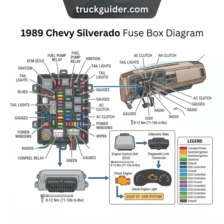
The diagram illustrates layout schematics, terminal pinouts, fuse amperages, and relay assignments for both the under-hood power distribution center and the interior kick panel. It identifies critical circuits supplying the engine ECU, starter solenoid, fuel injectors, headlights, cabin blower, and OBD-II port across V6 and V8 engine configurations.
How do I read the 2000 toyota tundra fuse box diagram?
Match the embossed layout inside the plastic cover to the physical grid. Identify circuit abbreviations like EFI, AM1, or DOME, then verify the color-coded amperage rating stamped on the fuse body. Trace designated branch circuits directly to identify which auxiliary components or control modules share that individual power feed.
What are the main components in 2000 toyota tundra fuse box diagram?
Key components include mini blade fuses (5A to 30A), high-capacity JCASE cartridge fuses, the main alternator fusible link, and standard ISO relays. Critical control circuits include the EFI relay powering the ECU, the starter relay, the C/OPN fuel pump relay, and dedicated diagnostic bus fuses protecting the OBD-II port.
What are common problems with 2000 toyota tundra fuse box diagram?
Common issues include intermittent crank-no-start conditions caused by corroded EFI relay terminals, melted tail lamp circuits from trailer harness shorts, and blown 7.5A OBD fuses preventing scanner linkup. Water intrusion along the A-pillar can also induce terminal pin corrosion across the lower dashboard interior junction block.
Can I use 2000 toyota tundra fuse box diagram for DIY repair?
Yes, using the diagram allows owners to quickly isolate blown circuits using a basic 12V test light or multimeter. Swapping blown blade fuses, testing relay coil resistance, and checking hot-at-all-times terminal voltage are straightforward DIY tasks, though harness rewiring or melted block replacement demands intermediate electrical experience.
What tools do I need for 2000 toyota tundra fuse box diagram?
You need an automotive fuse puller or needle-nose pliers, a 12V automotive test light, a digital multimeter to measure continuity and parasitic draw, and an OBD-II scanner to clear any residual diagnostic code triggered by open circuit conditions or temporary ECU power interruptions during your diagnostic procedure.