2003 Chevy Silverado Fuel Line Diagram: Routing & Repair (2026)

The 2003 Chevy Silverado fuel line diagram routes a 3/8-inch supply line, 5/16-inch fuel return line, and 1/4-inch EVAP vapor line along the driver-side frame rail. Fuel moves from the in-tank pump through an inline frame filter to the engine fuel rail, operating between 55 and 62 PSI for Vortec gas engines.
📌 Key Takeaways
- Factory fuel lines use 3/8-inch main feed, 5/16-inch fuel return line, and 1/4-inch EVAP tubing routed along the left inner frame rail.
- Normal Vortec fuel rail operating pressure is 55 to 62 PSI; LB7 Duramax models use a vacuum-fed CP3 high pressure fuel pump (HPFP).
- Factory quick-disconnect fittings require 3/8-inch and 5/16-inch disconnect tools; never pry nylon retaining tabs with screwdrivers.
- Corrosion along the mid-chassis frame rail bend near the transmission crossmember is the primary leak failure point.
- Pre-bent stainless steel or flexible braided nylon replacement line kits eliminate dropping the fuel tank in DIY installations.
The 2003 Chevrolet Silverado 1500, 2500HD, and 3500 series trucks built on the General Motors GMT800 platform feature complex fuel plumbing that differs significantly between Vortec gasoline engines and Duramax diesel powertrains. Navigating the 2003 chevy silverado fuel line diagram requires an understanding of chassis-rail routing, line diameters, quick-disconnect fitting styles, and system pressures. Because 2003 represents a transitional year for GM fuel architecture—bridging traditional manifold-vacuum-referenced return systems and later returnless configurations—correctly identifying your line routing is essential for accurate diagnostics, safe fuel system depressurization, and corrosion repair.
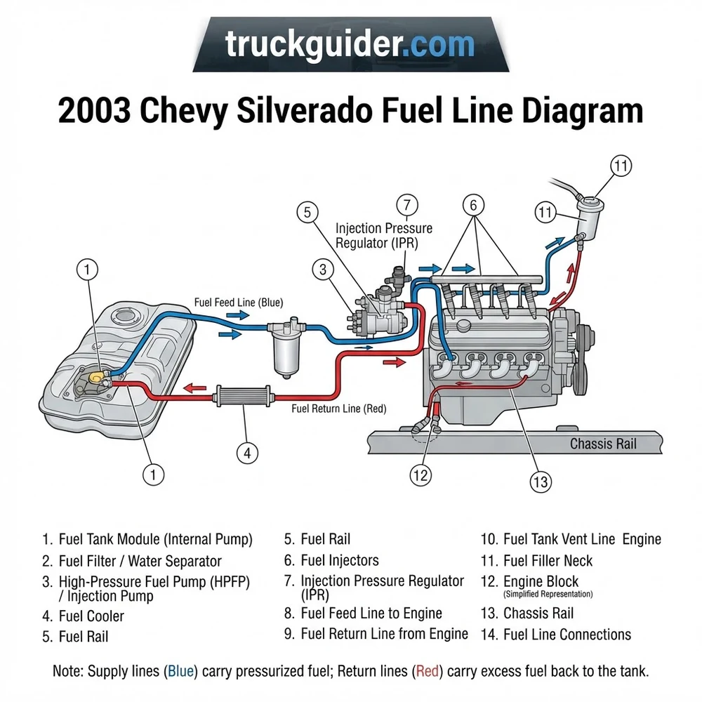
2003 Chevy Silverado Fuel Line Diagram and Frame Rail Routing


On all 2003 GMT800 chassis configurations (regular cab, extended cab, and crew cab across short and long bed wheelbases), the primary fuel plumbing travels exclusively along the inside channel of the left-hand (driver-side) frame rail. As shown in the diagram above, this routing shields the high-pressure circuits from driveline contact and passenger-side exhaust heat while maintaining proximity to the fuel tank and transmission bellhousing.
The factory bundle on standard Vortec V8 gasoline platforms (4.8L LR4, 5.3L LM7/L59, and 6.0L LQ4) consists of three rigid steel tubes secured by snap-in composite chassis clips bolted directly to the frame web:
- Fuel Supply Line (Feed Line): 3/8-inch outside diameter (OD) rigid steel tubing. This circuit originates at the in-tank modular fuel pump reservoir, connects through an inline fuel filter mounted to the inner frame rail roughly beneath the driver-side floor pan, runs up the front frame arch, and transitions to a flexible braided hose at the rear of the engine before attaching to the driver-side fuel rail inlet.
- Fuel Return Line: 5/16-inch OD rigid steel tubing. The return circuit originates at the vacuum-operated fuel pressure regulator mounted on the engine fuel rail. It runs parallel to the supply line along the frame rail, bypassing the fuel filter, and routes straight back to the fuel sender assembly drop tube to dump unmetered fuel back into the tank reservoir.
- EVAP Vapor Line: 5/16-inch OD (stepping to 3/8-inch at specific flex interfaces) steel and nylon composite line. This line links the EVAP canister purge solenoid on the intake manifold to the chassis-mounted EVAP charcoal canister and fuel tank roll-over vent valve.
While 2003 Silverado gas engines overwhelmingly utilize this three-line return-style system, select late-production flex-fuel (L59) and transition-build models feature a returnless system with a single 3/8-inch supply line and an internal regulator integrated into the in-tank module. Always cross-reference the intake manifold fuel rail: two metal hard lines indicate a return-style rail; a single inlet line confirms a returnless configuration.
The routing bends upward sharply over the rear axle crossmember to eliminate pinch points during suspension articulation. At the front, the lines follow the transmission bellhousing contour, terminating in flexible nylon-reinforced or stainless-braided sections that absorb engine roll and torque vibration under load.
2003 Chevy Silverado Fuel Line Diagram Component Breakdown


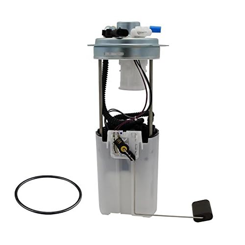

Understanding each mechanical connection, fitting standard, and operational parameter is critical when servicing or replacing sections of the fuel infrastructure. The 2003 Silverado employs SAE J2044 standard quick-connect male tube ends mating to female snap-lock retainers, alongside traditional threaded connections on specific filter designs.
| Component | Fitting Type & Size | Line Circuit | Operating Specs / Part Data |
|---|---|---|---|
| Fuel Pump Module / Sending Unit | 3/8″ Push-Connect (Supply) 5/16″ Push-Connect (Return) 3/8″ or 5/16″ (Vapor) |
Tank Top Outlet Port | 12V DC power; OEM pressure capability: 80+ PSI deadhead; Delphi FG0407 / AC Delco MU1613 |
| Inline Fuel Filter | 3/8″ Quick-Disconnect (Inlet/Outlet) or M16x1.5 O-ring Threaded | Chassis Feed Line | Rated for 60 PSI continuous; AC Delco GF652 / Wix 33595; 10-micron filtration rating |
| Fuel Rail Assembly | 3/8″ Quick-Disconnect Male (Feed) 5/16″ Quick-Disconnect Male (Return) |
Engine Manifold Interface | Stainless/plated steel construction; incorporates Schrader test valve (1/4″ SAE flare) |
| Fuel Pressure Regulator (FPR) | Internal O-ring Rail Pocket with Snap-Ring Retainer | Fuel Return Line Control | 55–62 PSI static KOEO; 48–54 PSI at idle with engine vacuum line attached; AC Delco 217-3028 |
| EVAP Purge Solenoid | 5/16″ Quick-Disconnect Barbed Nylon | Vapor Recovery Circuit | Duty-cycle pulsed by PCM (12V PWM); normally closed; GM Part #12581282 |
Vortec Fuel Rail Pressure Spec: 380–425 kPa (55–62 PSI) Key On, Engine Off (KOEO). When manifold vacuum is applied to the fuel pressure regulator nipple via a handheld vacuum pump, fuel pressure must drop proportionally (typically 3 to 10 PSI reduction depending on vacuum depth).
The quick-connect joints utilize internal dual fluorosilicone O-rings separated by a plastic spacer ring. The secondary outer plastic retainer clip (commonly a duckbill or push-button style) serves purely as a mechanical lock to prevent line ejection under line pressures that can exceed 60 PSI during cold-start priming cycles.
Vortec Gas vs. Duramax Diesel Fuel Cooler and Primer Setup


Plumbing variations between the standard gasoline Vortec V8 engines and the 6.6L Duramax Diesel (LB7 engine code in 2003) are structural. The gasoline system operates under constant positive pressure generated by an electric submersible pump. In sharp contrast, the LB7 Duramax utilizes a negative-pressure (suction) feed system from the tank to the engine bay, having no electric lift pump in stock configuration.
| Design Parameter | Vortec 4.8L / 5.3L / 6.0L Gas | Duramax 6.6L V8 Diesel (LB7) |
|---|---|---|
| Primary Fuel Supply Method | In-tank electric high-pressure turbine pump | Engine-driven Bosch CP3 high pressure fuel pump (HPFP) vacuum suction |
| Feed System Pressure | Positive: 55 to 62 PSI | Negative: -3 to -5 in-Hg vacuum (supply line from tank to CP3 pump) |
| Priming & Filtration Mechanism | Inline frame-mounted steel canister filter | Under-hood fuel bowl assembly with integrated manual primer pump and air bleed screw |
| Thermal Fuel Management | None (ambient dissipation along frame lines) | 12V fuel heater in filter head; chassis-mounted extruded aluminum fuel cooler on return line |
| Fuel Rail Pressure Control | Mechanical spring/diaphragm FPR on fuel rail | Electronic injection pressure regulator (FPR2) modulated via ECM (up to 23,000+ PSI rail pressure) |
On the 2003 LB7 Duramax, the fuel lines routed along the frame rail are 1/2-inch OD (feed) and 3/8-inch OD (return). Because the Bosch CP3 high pressure fuel pump (HPFP) compresses fuel up to 160 MPa (23,200 PSI), excess fuel bypassed by the injectors and high-pressure pump absorbs extreme thermal energy. If routed directly back to the plastic fuel tank without cooling, this return fuel could soften tank seams and degrade the sender module.
To eliminate this risk, GM engineers integrated an extruded fin-and-tube fuel cooler directly into the return line circuit. Mounted on the inside of the frame rail forward of the fuel tank, this heat exchanger drops diesel return temperatures by 30°F to 50°F before the fuel re-enters the tank. Furthermore, cold-weather diesel operation demands the integrated fuel heater located inside the engine-bay filter head to prevent paraffin wax crystals from plugging the 2-micron diesel filter medium.
Symptoms of 2003 Silverado Fuel Line Corrosion and Failures

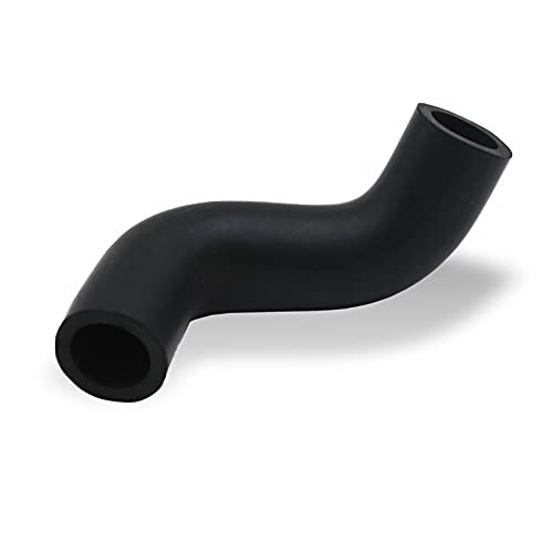


Due to the environmental exposure of the GMT800 chassis, line degradation represents one of the most common failure modes on these vehicles. Vehicles operating in geographic salt belts experience severe rust-jacking between the steel tubing and the plastic frame-retaining clips.
1. Raw Gasoline Odors Near Driver-Side Cab Corner
The steel hard lines pass between the inside of the frame rail and the exterior surface of the fuel tank. Road debris, magnesium chloride, and moisture become trapped in this unwashed pocket, corroding the lines from the outside in. Pinholes typically form first along the top arc of the supply or fuel return line directly forward of the tank sending unit, creating strong gasoline fumes that migrate directly into the cab.
2. Extended Engine Cranking and Hard Start (Loss of Rest Pressure)
According to OEM technical specifications, the 2003 Silverado fuel system must hold residual line pressure above 45 PSI for at least 10 minutes following key-off. Pinholes, cracked quick-disconnect O-rings, or a leaking check valve cause rail pressure to immediately bleed down to 0 PSI. When cranking, the engine must rotate for 5 to 10 seconds while the fuel pump recharges the depleted feed pipe, triggering extended crank times.
3. Check Engine Light (DTCs P0171, P0174, P0440, P0455)
Line failures register distinctive diagnostic trouble codes depending on which circuit compromises integrity:
- DTC P0171 / P0174 (System Too Lean, Banks 1 & 2): Restricted or leaking fuel supply lines reduce fuel volume delivery under load, resulting in severe fuel rail pressure drops during acceleration.
- DTC P0440 / P0442 / P0455 (EVAP System Leaks): Perforation of the 5/16-inch EVAP vapor line eliminates the PCM’s ability to pull vacuum on the fuel tank during monitor tests, triggering emission fault codes.
Corroded steel fuel lines under 60 PSI of pressure can fail catastrophically during heavy throttle demand. Never patch high-pressure steel supply lines with standard rubber fuel hose and worm-drive hose clamps; fuel-injection hose (SAE J30R9) with rolled-edge EFI clamps or complete line replacement is mandatory to prevent underbody vehicle fires.
4. Fluid Weepage at OEM Quick-Disconnect Fittings
The female connector collars at the fuel filter and fuel pump top plate feature internal fluorosilicone seals that harden and lose elasticity over years of thermal cycling. When the vehicle sits overnight in sub-freezing temperatures, the metal and plastic shrink at dissimilar rates, creating momentary cold-weather fuel leaks that vanish once underhood or exhaust temperatures warm the chassis.
Replacing 2003 Chevy Silverado Fuel Lines: Step-by-Step Installation
Replacing deteriorated rigid steel lines on the GMT800 platform with pre-bent OEM-style steel lines often requires removing the truck cab or unbolting the transmission crossmember due to complex frame bends. Consequently, mechanics and experienced DIYers frequently utilize flexible pre-formed braided stainless steel or high-density nylon replacement line kits (such as Dorman or S.U.R.&R. systems) that feed through the existing frame clips without cab removal.
-
Depressurize the High-Pressure Fuel Circuit:
Locate the underhood electrical center (fuse box) on the driver-side fender. Remove the 20A “FUEL PUMP” fuse (Fuse #9 in standard layouts) or the primary fuel pump relay. Crank the engine for 5 to 7 seconds until it stalls, then crank for an additional 3 seconds to clear residual line pressure. Remove the protective cap on the driver-side fuel rail Schrader test valve and depress the valve core using a rag and a fuel pressure gauge bleed tube to ensure 0 PSI remains in the manifold circuit. Disconnect the negative battery terminal. -
Gain Tank Access (Bed Removal vs. Tank Dropping):
Depending on shop equipment, choose between dropping the fuel tank or lifting the truck bed. Lifting the truck bed is mechanically faster: remove the six or eight 18mm bed-to-frame mounting bolts, unfasten the three 7mm screws holding the fuel filler neck to the bedside, disconnect the rear taillight wiring harness connector at the rear bumper, and hoist or slide the bed rearward 24 inches. This exposes the top of the fuel pump module, sending unit fittings, and rear line runs without dealing with fuel weight. -
Disconnect Chassis Quick-Disconnect Fittings:
Spray the male/female connection joints thoroughly with penetrating fluid to flush out impacted grit. Compress and remove the secondary plastic retaining safety clips. Insert an aluminum or steel fuel line quick-disconnect tool (3/8-inch for supply, 5/16-inch for return and EVAP) squarely into the back of the female connector housing. Push the line toward the fitting while pressing the tool inward to spread the internal garter spring tabs, then pull the line cleanly off the steel tube bead. -
Extract Damaged Frame-Rail Segments:
Pry open the factory plastic retainers mounted along the inner driver frame rail using a flat composite trim tool. Disconnect the inlet and outlet connections of the inline fuel filter. Carefully unthread the degraded steel tubes from between the transmission crossmember, steering shaft clearance area, and brake lines. -
Route and Fasten New Fuel Line Kit:
Route the replacement pre-formed nylon or braided stainless lines along the factory routing path. Maintain at least 3 inches of clearance from the exhaust system and steering column linkage. Snap the new lines into the original chassis clips (or install rubber-insulated P-clamps where original plastic clips are brittle or shattered). Ensure the supply line routes through a new inline fuel filter, verifying that the directional flow arrow on the filter points forward toward the engine bay. -
Connect Rail and Fuel Module Interfaces:
Lubricate the male quick-connect tube beads on the engine fuel rail and the tank sending unit with clean engine oil or silicone spray (never use petroleum jelly, which degrades internal fluorosilicone seals). Push the female connectors onto the male spigots until an audible mechanical click is heard and felt. Pull back firmly on each joint with moderate hand pressure to confirm positive latching. Reinstall the secondary safety locking clips. -
System Prime, Bleed, and Leak Inspection:
Reinstall the fuel pump fuse/relay and reconnect the negative battery cable. Turn the ignition key to the ON position (KOEO) for 3 seconds, then turn it OFF for 5 seconds; repeat this cycle 4 times to allow the in-tank pump to purge air through the return line and pressurize the feed pipe. Inspect every joint, fitting, and the fuel filter seals for liquid leaks or vapor weepage before starting the engine. Verify 55–62 PSI operating pressure at the Schrader valve using an accurate mechanical gauge.
2003 Chevy Silverado Fuel Line Diagram and Diagnostics FAQ
What size are the fuel lines on a 2003 Chevy Silverado?
On gasoline Vortec models (4.8L, 5.3L, 6.0L), the fuel supply line is 3/8-inch OD, the fuel return line is 5/16-inch OD, and the EVAP vapor line is 5/16-inch OD. On the 6.6L LB7 Duramax diesel model, the fuel supply line from the tank to the filter head is 1/2-inch OD, while the engine-to-tank fuel return circuit uses 3/8-inch OD line to accommodate the high volume returned by the Bosch CP3 high pressure fuel pump.
Does a 2003 Silverado have a return fuel line or returnless system?
The vast majority of 2003 Silverado trucks feature a traditional two-line return-style fuel rail system. This can be confirmed by looking at the driver-side fuel rail: if there is a vacuum-operated fuel pressure regulator mounted to the rail with a 5/16-inch steel line extending back down the engine block, it is a return-style system. Late-model transitions and select flex-fuel configurations carry a returnless rail with an internal tank regulator, eliminating the frame-rail return line entirely.
Where is the inline fuel filter located on a 2003 Silverado?
The inline fuel filter is mounted along the inside surface of the driver-side frame rail, roughly aligned underneath the transition between the cab floor and the driver’s seat. It is positioned inline exclusively on the 3/8-inch fuel supply line. 2003 was among the final model years featuring this easily serviceable frame filter; GM eliminated external inline fuel filters on gasoline light trucks in subsequent model years, relying solely on in-tank pump sock strainers.
Why does the Duramax diesel have a fuel cooler on the return line?
The Duramax 6.6L common-rail injection system operates at up to 23,000+ PSI. The injection pressure regulator bypasses significant volumes of diesel fuel back into the return circuit. Compressing fuel to extreme pressures introduces massive thermal energy. The chassis-mounted extruded aluminum fuel cooler transfers this heat out of the fuel before it reaches the polymer fuel tank, preventing heat-induced tank deformation, fuel boiling, and high-temperature viscosity breakdown.
How do you release stuck GM quick-disconnect fuel line fittings?
Quick-disconnect fittings on the 2003 Silverado seize when road grit packs tightly behind the internal garter spring. To release a stuck fitting, blast the inside cavity of the female connector with pressurized brake cleaner or penetrating lubricant while manipulating the connector back and forth over the hard line. Push the female connector deeper onto the male tube before inserting the disconnect tool. This creates physical clearance between the internal spring fingers and the tube locking bead, allowing the tool to fully expand the retaining spring and release the line.