2003 Toyota Tacoma Engine Diagram: 3.4L 5VZ Breakdown 2026

The 2003 Toyota Tacoma engine diagram covers the 2.4L 2RZ-FE, 2.7L 3RZ-FE, and 3.4L 5VZ-FE DOHC platforms. The diagram maps the dual overhead camshaft layout, cylinder head assembly, timing belt/chain routing, and bottom end connecting rod alignment to the forged crankshaft, specifying standard 5VZ-FE rod journal oil clearance at 0.0014–0.0022 inches.
📌 Key Takeaways
- 5VZ-FE 3.4L V6 connecting rod bearing oil clearance spec is 0.0014–0.0022 in (0.036–0.056 mm) with rod cap bolt torque at 25 ft-lb plus 90 degrees.
- Dual overhead camshaft (DOHC) valve train requires precise timing alignment marks on the cam pulleys and crankshaft sprocket to prevent timing error codes.
- Cylinder head torque on the 3.4L uses a multi-step sequence ending at 25 ft-lb plus two successive 90-degree angle rotations using new TTY bolts.
- Common failure point includes valve cover gasket seepage degrading coil-on-plug boots and lower intake manifold gasket leaks causing cylinder misfires.
- Professional intervention recommended for crankshaft main journal align-honing, whereas timing belt and valve cover servicing are standard DIY procedures.
Navigating the powertrain architecture of the first-generation truck requires understanding the distinct mechanical nuances across its three production powerplants: the 2.4-liter 2RZ-FE, the 2.7-liter 3RZ-FE, and the 3.4-liter 5VZ-FE. As a late-stage iteration of the first-generation platform (1995.5–2004), the 2003 model year integrated refined Toyota Computer Controlled System (TCCS) engine management, modern evaporative emission control (EVAP) circuits, and model-specific waste-spark or coil-on-plug electronic ignition layouts. Whether you are executing a full bottom-end overhaul, mapping sensor pinouts, or setting valvetrain clearances, referencing a verified 2003 Toyota Tacoma engine diagram prevents reassembly errors and ensures factory mechanical tolerances remain within OEM limits across every operational assembly.
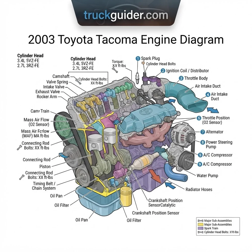
2003 Toyota Tacoma Engine Diagram & Specs by Engine Option



Before referencing a 2003 Toyota Tacoma engine diagram, you must identify the exact engine platform installed in your chassis. Toyota equipped the 2003 Tacoma with three distinct inline-four and V6 engines. The 2WD base regular cab models typically feature the 2.4L 2RZ-FE; 4WD and PreRunner four-cylinder models house the 2.7L 3RZ-FE; and V6 configurations utilize the 3.4L 5VZ-FE. You can verify your installed powertrain by inspecting the fifth digit of the Vehicle Identification Number (VIN): L designates the 2RZ-FE, M designates the 3RZ-FE, and N indicates the 5VZ-FE.



The structural designs of these engines differ significantly. The 2RZ-FE and 3RZ-FE feature a deep-skirt cast-iron engine block paired with a cast-aluminum dual overhead camshaft (DOHC) cylinder head driven by a dual-row timing chain. The 3RZ-FE incorporates dual counter-rotating balance shafts inside the crankcase to neutralize secondary vertical vibrations inherent to large-displacement four-cylinder engines. In contrast, the 60-degree V6 5VZ-FE utilizes a cast-iron engine block with aluminum cylinder heads driven by a rubber-toothed timing belt, featuring four valves per cylinder actuated by bucket-and-shim mechanical lifters.
| Engine Specification | 2.4L 2RZ-FE (I4) | 2.7L 3RZ-FE (I4) | 3.4L 5VZ-FE (V6) |
|---|---|---|---|
| Displacement / Configuration | 2,438 cc (Inline-4) | 2,693 cc (Inline-4) | 3,378 cc (60° V6) |
| Bore x Stroke | 95.0 mm x 86.0 mm | 95.0 mm x 95.0 mm | 93.5 mm x 82.0 mm |
| Compression Ratio | 9.5:1 | 9.5:1 | 9.6:1 |
| Valvetrain System | DOHC 16-valve, Shim-over-bucket | DOHC 16-valve, Shim-over-bucket | DOHC 24-valve, Shim-over-bucket |
| Timing Drive Type | Double-row roller chain | Double-row roller chain | Toothed cogged belt (Non-interference) |
| Firing Order | 1-3-4-2 | 1-3-4-2 | 1-2-3-4-5-6 |
| Ignition Architecture | Direct Ignition (4 individual coils) | Direct Ignition (4 individual coils) | Waste-spark (3 coil packs on Bank 1) |
| Oil Capacity (with filter) | 5.7 US qt (5.4 L) | 5.8 US qt (5.5 L) | 5.5–5.7 US qt (5.2–5.4 L) |
Understanding these dimensional and mechanical variations is critical when interpreting your engine schematic. For instance, the 5VZ-FE utilizes a crossflow cylinder head design with an intake plenum splitting into individual cast-aluminum runners across both banks. When performing top-end diagnostics or a teardown, consult our comprehensive 5VZ-FE torque specifications to maintain proper clamping force across the aluminum heads and prevent gasket failure.
2003 Toyota Tacoma Engine Diagram: Core Bay Layout and Architecture


A comprehensive spatial map of the 2003 engine compartment ensures rapid identification of high-frequency service points, intake assemblies, and electrical monitoring components. When studying the 2003 Toyota Tacoma engine diagram, locate the operational subsystems grouped across the front, top, and lower quadrants of the engine bay:
- Intake Plenum and Throttle Body Assembly: Positioned longitudinally along the center line on the 2RZ/3RZ and resting centrally between the banks on the 5VZ-FE. The cast-aluminum intake plenum connects to the throttle body via a four-bolt flange. On the 2003 model year, the throttle body houses an integrated Rotary Solenoid Idle Air Control Valve (IACV) mounted underneath, supplemented by a 3-wire or 4-wire Throttle Position Sensor (TPS). The TPS sends a linear voltage signal (typically 0.5V closed to 4.0V+ wide-open throttle) along the signal wire back to the engine control module (ECM).
- Mass Air Flow (MAF) Sensor: Clamped directly to the intake air filter housing tube ahead of the rubber intake bellow. The 2003 Tacoma utilizes a platinum hot-wire MAF sensor (Toyota part number 22204-75030 / 22204-07010 depending on production month). The sensor uses a 5-pin terminal: Pin 1 (+B battery supply through EFI relay), Pin 2 (E2 chassis sensor ground), Pin 3 (VG airflow voltage output, reading 1.1–1.5V at hot curb idle and rising to roughly 3.5V under load), Pin 4 (THA intake air temp thermistor), and Pin 5 (E2 sensor return).
- Ignition Coils and Secondary Wire Routing: On the four-cylinder engines (2RZ-FE / 3RZ-FE), the 2003 model features direct coil-on-plug packs mounted directly over each spark plug tube, controlled via individual igniter signal circuits from the ECM. On the 5VZ-FE V6, the factory uses a waste-spark configuration: three dual-output ignition coil packs mount exclusively atop the passenger side cylinder head (Bank 1: Cylinders 1, 3, and 5). High-tension silicone plug wires bridge across the intake manifold plenum to fire the paired companion cylinders on the driver-side cylinder head (Bank 2: Cylinders 4, 6, and 2). Cylinder pairing operates as 1-4, 3-6, and 5-2.
- Cooling System Circuitry and Thermostat Housing: Coolant flow originates at the timing cover-mounted centrifugal water pump. On the 5VZ-FE, the thermostat is placed on the cold side (inlet side) of the cooling system, located inside a cast neck at the lower radiator hose inlet rather than on the upper cylinder head outlet. The OEM thermostat is rated for 180°F (82°C) and incorporates an offset jiggle valve that must be oriented at the 12 o’clock (straight up) position during installation to allow trapped air to bypass during coolant refills. On the 2RZ/3RZ, the thermostat resides within the water inlet housing alongside the front-right lower portion of the engine block.
- Fuel Rail and Injector Network: The multipoint sequential fuel rail houses high-impedance top-feed injectors (13.4–14.2 ohms at 68°F / 20°C). Fuel pressure is regulated by a mechanical vacuum-referenced Fuel Pressure Regulator (FPR) seated on the return side of the rail, holding base fuel pressure at 38–44 PSI with the vacuum sensing hose disconnected and plugged.
When testing the MAF sensor on the 2003 Tacoma, verify terminal voltages directly back-probed at the ECM harness connector (E9/E10). Signal drift or contamination of the exposed hot-wire filament will offset the short-term fuel trim (STFT) beyond ±15%, prompting lean trouble codes P0171 without exhibiting a hard component failure.
Accessory Belt and Vacuum Routing Across the Engine Block


Tracing mechanical drive belts and pneumatic lines requires systematic adherence to factory routing schematics. Incorrect accessory belt tension will rapidly destroy water pump bearings or cause alternator slippage, while crossed vacuum lines trigger emission diagnostic trouble codes and irregular idle speeds.



The accessory drive belt system on the 2003 Tacoma utilizes multiple V-ribbed serpentine belts driven off the harmonic balancer attached to the front of the crankshaft. On the 5VZ-FE, three independent belts run from the main crankshaft pulley:
- Alternator and Water Pump Belt: Routes around the inner crankshaft pulley groove, loops under the water pump pulley, and wraps around the alternator pulley. Belt tension is set manually by loosening the alternator pivot bolt and turning the 12mm jack-screw adjuster on the lower mounting ear.
- Air Conditioning (A/C) Compressor Belt: Routes from the center pulley groove of the crankshaft up to the A/C compressor clutch pulley, tensioned by an independent flat idler pulley bracket located on the lower right front of the engine block.
- Power Steering Pump Belt: Routes around the outer crankshaft pulley groove to the power steering vane pump pulley. Tension is adjusted using a pry-slot leverage point behind the pump bracket after loosening the 14mm pivot and slide-lock fasteners.
Accessory belt deflection specifications: For a new belt, apply 22 lbf (98 N) midway between pulleys to achieve 7.0–9.0 mm of deflection. For a used belt, set tension to achieve 11.5–13.5 mm of deflection. The harmonic balancer crankshaft pulley bolt requires precisely 217 ft-lb (294 Nm) of torque on the 5VZ-FE, and 195 ft-lb (265 Nm) on the 2RZ/3RZ.
The vacuum hose network on the 2003 model features consolidated EVAP routing compared to early first-generation Tacomas. The primary reference for your engine bay is the Vehicle Emission Control Information (VECI) label, affixed to the underside of the steel hood. A rigid metal vacuum gallery is bolted across the top of the intake plenum, distributing manifold vacuum to several critical actuators:
- Fuel Pressure Regulator (FPR) Line: Connects directly from a dedicated port behind the throttle plate on the upper plenum to the vacuum nipple on the FPR diaphragm. Any cracking in this line prevents the fuel pressure from dropping at idle, causing rich running conditions.
- EVAP Purge Vacuum Switching Valve (VSV): Located on the driver-side intake manifold runner or inner fender apron. One vacuum port connects to the intake plenum air stream; the second connects to the vapor canister pipe passing down along the chassis rail to the fuel tank.
- Automatic Disconnecting Differential (ADD) Circuit (4WD Models): Utilizes a dedicated vacuum reservoir bottle tucked inside the driver-side fender well, routing through a dual-solenoid VSV bank on the inner fender wall down to the pneumatic vacuum actuator on the front differential carrier housing.
Never swap the vacuum supply port feeding the Fuel Pressure Regulator with the port feeding the EVAP purge solenoid. Supplying pulsing fuel vapor purge vacuum to the FPR diaphragm causes unstable fuel rail pressure fluctuations, resulting in misfire codes P0300 through P0306.
For complex diagnostic testing of the vapor recovery system, consult our dedicated EVAP vacuum routing diagrams to trace tank pressure sensor connections and check valve orientations.


Common Failure Points: Cylinder Head, Valve Train, and Lubrication


The mechanical architecture of the 2003 Tacoma platform exhibits distinct wear patterns and component degradation over high operating hours. Integrating troubleshooting routines with your 2003 Toyota Tacoma engine diagram allows you to isolate faults quickly without unnecessary parts replacement.
- Valve Train Clearance Tightening (Recession): On both the 2RZ/3RZ and 5VZ-FE, the solid shim-over-bucket valve train lacks hydraulic lifters. Over extended mileage (especially past 120,000 miles), the exhaust valves pound into their valve seats, reducing the cold valve clearance. If valve lash reaches zero, the exhaust valve remains cracked open during the combustion event, resulting in a burned valve face and cylinder head compression loss (typically on cylinders 3 or 4 on I4 engines, and cylinder 5 or 6 on V6 engines). Cold clearance specs must be checked periodically using feeler gauges: Intake: 0.13–0.23 mm (0.005–0.009 in); Exhaust: 0.25–0.35 mm (0.010–0.014 in). Adjustments require measuring the old shim and installing a replacement calculated by:
Thickness of New Shim = Thickness of Old Shim + (Measured Clearance – Desired Clearance). - Cylinder Head Gasket Integrity: On the 3.4L 5VZ-FE, early production models (1995.5–1998) were notorious for head gasket leaks between cylinders and coolant passages. While 2003 models utilize an upgraded Multi-Layer Steel (MLS) gasket from the factory, failures can still occur past 200,000 miles if the cooling system is neglected. Breaches typically appear between the combustion chamber fire ring and the rear coolant jackets on cylinders 3 and 5. Cylinder head bolts must always be discarded and replaced upon teardown; they are torque-to-yield fasteners torqued initially to 25 ft-lb (34 Nm), followed by two sequential 90-degree clockwise turns.
- Camshaft Oil Seals and Valve Cover Gaskets: The half-moon aluminum plugs at the rear of the cylinder head, along with the front camshaft oil seals, become brittle from heat cycles. Oil migrates downward behind the timing cover backing plate, contaminating the timing belt (on the 5VZ-FE) or dripping directly onto the hot exhaust crossover pipe. When resealing the valve covers, clean and apply ThreeBond 1207B or equivalent Form-in-Place Gasket (FIPG) sealant around the cam half-moons and corner transition steps of the cylinder head casting.
- Oil Pan Gasket Failures and Sump Sealing: The 2003 Tacoma does not utilize a stamped pre-formed rubber or cork oil pan gasket. Both the two-piece oil pan assembly on the 5VZ-FE (consisting of an upper aluminum structural baffle pan and a lower stamped steel reservoir) and the single deep-well pan on the 2RZ/3RZ use pure RTV liquid sealant (Toyota OEM Seal Packing 08826-00088). Leaks frequently originate near the rear arch where the oil pan mates over the rear main crankshaft seal housing. Flange bolts must be torqued in a crisscross sequence to 65 in-lb (7.5 Nm); over-torquing crushes the sealant bead out of the mating channel, producing continuous leaks.
- Piston Ring Sticking and Connecting Rod Bearing Fatigue: While bottom-end failures are uncommon due to forged connecting rods and structural cross-bolted main bearing caps, extended oil drain intervals cause oil control rings on the aluminum piston skirts to coke with carbon. This results in heavy oil consumption without visible external leakage. Connecting rod clearance should measure 0.028–0.052 mm (0.0011–0.0020 in) with a maximum wear limit of 0.08 mm (0.0031 in). Inspect journal surfaces on the forged steel crankshaft using Plastigauge during any bottom-end refurbishment.
- Timing Belt and Tensioner Wear (5VZ-FE): The 5VZ-FE timing drive requires service at 90,000-mile or 72-month intervals. The hydraulic timing belt tensioner can lose damping pressure, allowing the belt to whip under deceleration and jump timing teeth on the camshaft pulleys. Reference our step-by-step timing belt replacement guide for alignment mark relationships between the crankshaft sprocket notch and the camshaft timing gears.
| Component Fastener | Torque (ft-lb) | Torque (in-lb / Nm) | Thread Prep / Requirements |
|---|---|---|---|
| 5VZ-FE Crankshaft Damper Bolt | 217 ft-lb | 294 Nm | Clean threads, light engine oil on flange face |
| 3RZ-FE Crankshaft Damper Bolt | 195 ft-lb | 265 Nm | Factory dry or light engine oil |
| Camshaft Bearing Cap Bolts (5VZ-FE) | 12 ft-lb | 16 Nm | Torque evenly from center outward |
| Connecting Rod Cap Nuts (5VZ-FE) | 25 ft-lb + 90° | 34 Nm + 90° | Coat threads and seats with engine oil |
| Lower Steel Oil Pan Bolts/Nuts | — | 65 in-lb (7.5 Nm) | Toyota 08826-00088 FIPG bead (3–4 mm) |
| Spark Plugs (All 2003 Engines) | 15 ft-lb | 20 Nm | Anti-seize not recommended on plated shells |
2003 Toyota Tacoma Engine Diagram and Diagnostic FAQs
Is the 2003 Toyota Tacoma 3.4L 5VZ-FE an interference engine?


No, the 3.4L 5VZ-FE is a non-interference engine in its factory naturally aspirated configuration. If the timing belt snaps, strips teeth, or slips off the camshaft gears while driving, the valves will not contact the top surface of the piston head. However, if the engine block has been decked or the cylinder head has been significantly resurfaced during a rebuild, clearance tolerances are altered, which can introduce mechanical interference. In contrast, the 2.4L 2RZ-FE and 2.7L 3RZ-FE use timing chains with deep piston valve reliefs; chain breakage is extremely rare unless chain guide wear is ignored.
What is the correct ignition coil pairing on the 2003 Tacoma V6?
The 2003 5VZ-FE employs three waste-spark ignition coils mounted over the cylinders on Bank 1 (passenger side: Cylinders 1, 3, and 5). Each coil features an integrated boot that directly seats on its host cylinder, along with a secondary high-voltage wire outlet feeding the companion cylinder across the intake plenum on Bank 2 (driver side). The firing pairs are: Coil atop Cylinder 1 connects via wire to Cylinder 4; Coil atop Cylinder 3 connects via wire to Cylinder 6; and Coil atop Cylinder 5 connects via wire to Cylinder 2. Cross-connecting these secondary high-tension ignition leads results in a no-start condition or backfiring through the intake manifold.
How do you trace vacuum leaks on the 2003 Tacoma intake network?
Begin by viewing live Short Term Fuel Trim (STFT) and Long Term Fuel Trim (LTFT) values via an OBD-II scanner using our Toyota OBD-II trouble code directory. If total fuel trim (STFT + LTFT) exceeds +10% to +20% at idle but normalizes back to near 0% at 2,500 RPM, the problem is an unmetered air vacuum leak downstream of the MAF sensor. Using an automotive smoke machine, inject pressurized smoke into the intake boot through the brake booster vacuum reference line. Common failure sites on the 2003 bay diagram include the cracked rubber intake bellow accordions between the MAF and throttle body, hardened IACV bottom-gasket seals, and cracked rubber elbows on the PCV valve seated in the valve cover grommet.


What are the oil pan torque specifications and sealing requirements?


The lower stamped steel oil pan on all 2003 Tacoma engines requires a torque specification of only 65 in-lb (7.5 Nm) for its perimeter M6 bolts and nuts. You must not use a standard dry replacement gasket. Clean both sealing faces completely with brake cleaner or lacquer thinner to remove all residual oil and old sealant. Apply a continuous 3.0 mm to 4.0 mm bead of genuine Toyota Seal Packing (FIPG) part number 08826-00088 or ThreeBond 1207B inside the bolt hole centerlines. Bolt installation and preliminary snugging must occur within 10 minutes of application, and the engine must not be filled with motor oil for a minimum of 2 to 4 hours to permit complete curing of the elastomeric silicone bond.
Why does my 2003 Tacoma 2.7L 3RZ-FE exhibit a rough idle despite good ignition components?
If spark plugs, coil packs, and the MAF sensor test within factory resistance and voltage specifications, the primary culprit on the 2.7L 3RZ-FE is almost universally tight exhaust valve lash. As exhaust valves wear into their seats over miles of operation, the valve stem rises toward the camshaft base circle, reducing valve clearance to zero. This prevents the valve from seating fully against the cylinder head when hot, bleeding off dynamic cylinder compression and causing a low-RPM misfire code (P0300, P0303, or P0304). Remove the valve cover, rotate the engine to top dead center for each cylinder, and slide feeler gauges between the camshaft base circle lobes and the valve shims to confirm the required 0.25–0.35 mm exhaust gap.
Step-by-Step Guide to Understanding the 2003 Toyota Tacoma Engine Diagram
Identify – Verify the engine code (2RZ-FE, 3RZ-FE, or 5VZ-FE) via the emissions sticker on the underside of the hood.
Locate – Find the primary component group on the diagram, distinguishing the top-end cylinder head from the lower crankcase assembly.
Reference – Trace the camshaft timing marks and crankshaft TDC indicators against the diagram before belt or chain disassembly.
Torque – Fasten internal fasteners following the diagrammed sequences, ensuring connecting rod bolts reach 25 ft-lb plus 90 degrees.
Verify – Manually rotate the crankshaft two full revolutions clockwise to confirm valve train synchronization and mechanical clearance.
Troubleshoot – Check sensor connections at the camshaft position sensor and crankshaft reluctor ring if diagnostic misfire codes persist.