7-Way 2004 Chevy Silverado Trailer Wiring Diagram: 2026 Pinout

The 2004 Chevy Silverado 7-way RV blade trailer connector uses factory harness colors: White (Pin 1, Ground), Dark Blue (Pin 2, Brake Controller), Brown (Pin 3, Running Lights), Red/Black (Pin 4, 12V Auxiliary Power), Yellow (Pin 5, Left Turn Signal), Dark Green (Pin 6, Right Turn Signal), and Light Green (Pin 7, Reverse).
📌 Key Takeaways
- Factory 10-gauge White ground wire terminates at the rear driver-side chassis frame rail.
- Auxiliary power (Pin 4) requires installing the 40-amp Stud 1 fuse inside the underhood fuse block.
- Constant 12V auxiliary circuit supports up to 30 continuous amps for RV battery maintenance charging.
- Corrosion inside the bumper-mounted 7-way round junction socket causes 85% of intermittent lighting drops.
- Consult a certified technician if probing reveals open circuits inside the primary underbody harness loom.
The 2004 Chevrolet Silverado 1500, 2500, and 3500 pickup trucks (built on GM’s GMT800 platform) utilize an integrated trailering architecture centered around the factory RPO Z82 heavy-duty trailering equipment package. Navigating the 2004 Chevy Silverado trailer wiring diagram requires understanding how General Motors split power delivery between the underhood electrical center, the Mid-Bussed Electrical Center (MBEC) beneath the instrument panel, and the rear chassis harness. Whether you are installing an aftermarket electric brake controller, restoring a corroded rear junction block, or converting an existing 4-way flat connector to a fully powered 7-way RV blade socket, precise pinout tracing and circuit verification are required to ensure safe towing and eliminate dangerous voltage drops.
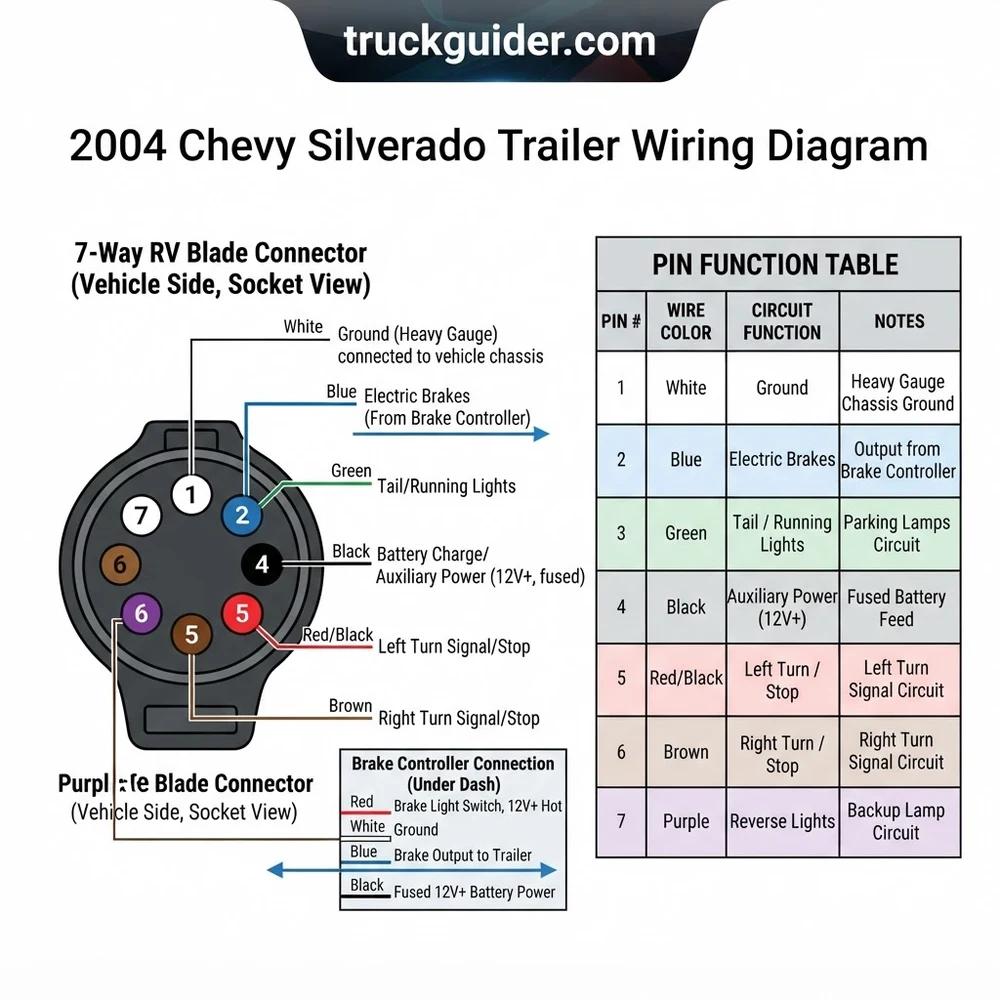
2004 Chevy Silverado Trailer Wiring Diagram: 7-Way RV Blade Pinout


Factory-equipped 2004 Silverado trucks equipped with the RPO Z82 trailering package feature a sealed harness terminating at the rear bumper with an industry-standard SAE J2863 / USCAR 7-pin socket. This connector combines vehicle lighting signals, auxiliary battery feed, electric trailer brake controller pulses, and a dedicated high-amperage ground pin into a single keyed housing. When referencing the socket face from the rear of the truck with the spring-loaded door hinge at the 12 o’clock position, each terminal blade occupies a fixed position defined by USCAR engineering standards.


Trucks ordered without the full Z82 package frequently left the assembly line with a standard 4-way flat trailer connector tapped into the rear taillight harness. A 4-way flat configuration carries only the fundamental DOT lighting circuits: chassis ground, running lights, left stop/turn, and right stop/turn. Upgrading from a 4-way flat connector to a 7-way RV blade socket requires running auxiliary 12V charging power and dedicated brake controller lines from the front of the vehicle to the rear hitch platform. Understanding the pin layout prevents catastrophic short circuits between high-amperage battery lines and sensitive lighting relays.
| Terminal Position | USCAR Identification | Circ. Number & Function | Factory Wire Gauge | Operating Parameters |
|---|---|---|---|---|
| 1 o’clock | Pin 4 (+12V AUX) | Circuit 742: Auxiliary Power | 10 AWG (Red/Black) | Constant 12V B+ via 40A Stud 1 Fuse |
| 3 o’clock | Pin 6 (RT TURN) | Circuit 19: Right Turn / Stop | 14 AWG (Dark Green) | Pulsed 12V (Turn) / Constant 12V (Stop) |
| 5 o’clock | Pin 2 (BRAKE) | Circuit 47: Electric Trailer Brake | 12 AWG (Dark Blue) | 0–12V Pulse-Width Modulated (PWM) output |
| 7 o’clock | Pin 1 (GND) | Circuit 150: Common Ground Pin | 10 AWG (White) | Direct chassis return to Ground G401 |
| 9 o’clock | Pin 5 (LT TURN) | Circuit 18: Left Turn / Stop | 14 AWG (Yellow) | Pulsed 12V (Turn) / Constant 12V (Stop) |
| 11 o’clock | Pin 3 (PARK/TAIL) | Circuit 9: Running Lights | 14 AWG (Brown) | Constant 12V switched via Trailer Park Relay |
| Center Pin | Pin 7 (REV/BACK) | Circuit 24: Reverse / Auxiliary | 16 AWG (Light Green) | Switched 12V when transmission in Reverse |
As shown in the technical table above, the factory USCAR receiver uses a specific physical keying notch along the outer shell to prevent reverse orientation. When probing terminals with a digital multimeter (DMM), ground your negative lead directly to the 7 o’clock terminal (Pin 1) rather than the bumper shell. This verifies that the return circuit back to the chassis maintains less than 0.2 ohms of resistance across the harness.
GM Factory Wire Color Reference vs Standard RV Blade Codes


A widespread source of electrical failure when servicing the 2004 Chevy Silverado trailer wiring diagram is the mismatch between OEM General Motors harness insulation colors and the standard RV aftermarket wire color code. GM manufactured the GMT800 chassis harness using SAE automotive wiring standards, whereas commercial trailer manufacturers strictly follow traditional RV trade associations (such as RVIA standards). Connecting wires strictly by matching color to color will result in blown fuses, inoperative brakes, or direct dead shorts across the auxiliary power circuit.
Never splice wires based purely on insulation color. In GM truck wiring, White is the dedicated ground return, while in standard RV wiring, White is also ground—however, GM uses Dark Green for Right Turn/Brake, whereas RV code uses Brown for Running Lights and Green for Right Turn. Interchanging these leads burns out the truck’s Underhood 10A TRLR fuses or damages LED control boards.
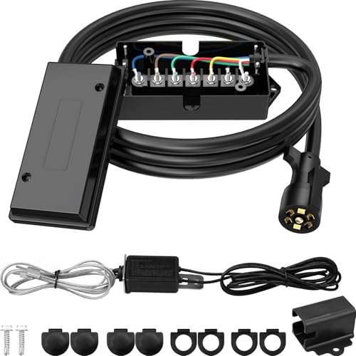
On the 2004 Silverado platform, the chassis wiring travels down the driver’s side frame rail inside corrugated split loom. Near the rear spare tire carrier, the harness enters a rear junction block or branches off via a sealed rear junction split. One branch feeds the truck’s independent taillight assemblies, while the heavy-gauge leads terminate directly into the 7-way receptacle. Furthermore, the ground circuit relies entirely on a dedicated rear chassis ground ring lug (chassis ground G401) bolted directly through the rear crossmember or frame web near the rear bumper mounting bracket.


| Circuit Role | GM GMT800 Factory Harness | Aftermarket Standard RV Code | Socket Blade Position |
|---|---|---|---|
| Ground Return | White (10 AWG) | White (10 AWG) | Terminal 1 (7 o’clock) |
| Electric Brake Output | Dark Blue (12 AWG) | Blue (12 AWG) | Terminal 2 (5 o’clock) |
| Running / Marker Lights | Brown (14 AWG) | Green (14 AWG) | Terminal 3 (11 o’clock) |
| 12V Battery Constant Charge | Red/Black stripe (10 AWG) | Black (10 AWG) | Terminal 4 (1 o’clock) |
| Left Turn Signal & Brake | Yellow (14 AWG) | Red (14 AWG) | Terminal 5 (9 o’clock) |
| Right Turn Signal & Brake | Dark Green (14 AWG) | Brown (14 AWG) | Terminal 6 (3 o’clock) |
| Reverse / Auxiliary Lockout | Light Green (16 AWG) | Yellow or Purple (16 AWG) | Terminal 7 (Center) |
When executing field repairs at the rear junction or taillight harness split, always use heat-shrink marine-grade crimp connectors. Scotchloks and vampire taps rapidly corrode from road brine thrown up by the rear wheels, leading to systemic voltage collapse across high-draw circuits such as trailer electric brakes.
How to Wire an Electric Brake Controller into the 2004 Silverado


Integrating an aftermarket proportional or time-delay electric brake controller into a 2004 Silverado is streamlined by GM’s cabin electrical architecture. All Z82-optioned trucks include dedicated interface routing between the cabin, the engine bay, and the rear bumper hitch. You do not need to splice into the fragile cold side of the brake pedal stop-lamp switch under the dash, which risks damaging sensitive logic inputs on the body control module (BCM). Follow this comprehensive procedure to wire the brake controller correctly.
Interface: Mid-Bussed Electrical Center (MBEC) Cavity C209 (Connector 8).
Factory Pigtail Harness: GM Part # 1530-5887 (or aftermarket equivalent harness adapter).
Circuit 47 Brake Output Wire: 12 AWG Dark Blue, rated up to 30 Amps continuous service.
B+ Supply Feed: Circuit 742 protected by underhood 30A or 40A Stud 1 / Stud 2 fuse.
- Locate the Mid-Bussed Electrical Center (MBEC): Position your workspace beneath the driver’s side instrument panel. Directly to the left of the brake and parking brake pedal assembly, mounted on the firewall kick panel, is a flat plastic distribution box covered by a snap-on plastic cover. Pull the bottom retaining tab outward and remove the cover to expose the multi-pin connector grid.
- Identify the Trailer Brake Controller Port: Within the MBEC, locate the 10-pin commercial connector cavity labeled “TRLR BRK” (designated as cavity C209 or Connector 8 depending on manual revisions). If your Silverado retains its original glovebox accessories, it included a factory blunt-cut brake controller pigtail harness equipped with a matching rectangular, keyed MBEC plastic plug.
- Connect the Aftermarket Controller Pigtail: Splice your aftermarket electric trailer brake controller wiring harness directly to the GM blunt-cut pigtail using self-soldering heat-shrink connectors or stepped crimp sleeves:
- Controller Black Wire (12V B+ Input): Connect to the GM Harness Red/Black wire (Terminal D, Circuit 742).
- Controller White Wire (Ground): Connect to the GM Harness Black wire (Terminal A, Circuit 150).
- Controller Blue Wire (Trailer Brake Output): Connect to the GM Harness Dark Blue wire (Terminal E, Circuit 47). This lead delivers the controlled pulse-width voltage back to the 7-way RV blade socket.
- Controller Red Wire (Stop Lamp Signal Input): Connect to the GM Harness Light Blue wire (Terminal B, Circuit 1622). This wire provides pure +12V exclusively when the service brakes are applied, signaling the controller to engage.
- Note: The GM pigtail may contain an extra Brown wire (Terminal C, dash illumination). Insulate this lead with heat shrink unless your aftermarket controller specifically supports analog dash dimming.
- Plug In and Route the Harness: Insert the keyed MBEC pigtail firmly into the C209 cavity until the center retaining tab clicks audibly. Dress the trailing wire loom clear of the moving steering shaft assembly, adjustable pedal mechanisms, and parking brake linkages using heavy-duty nylon zip-ties. Reinstall the plastic MBEC protective cover.
- Mount the Controller: Secure your electric brake controller bracket to the lower dash knee bolster using self-tapping fasteners. Ensure the unit is aligned parallel to the truck’s directional travel axis within the manufacturer’s allowed pitch angle to ensure its internal solid-state accelerometer accurately senses deceleration. Refer to our trailer brake controller gain adjustment guide for fine-tuning dynamic trailer balance.
- Complete Engine Bay Circuit Activation: By default from the factory, the power supply line feeding the MBEC brake connector port is left physically disconnected under the hood to prevent parasitic battery draw during dealership storage. You must manually activate this circuit in the underhood fuse box as detailed in the next section.
2004 Silverado Trailer Wiring Diagram: Fuses and 12V Auxiliary Power


The centralized power distribution for the 2004 Chevy Silverado trailer wiring system is housed within the Underhood Fuse Block, mounted to the inner driver’s side fender apron ahead of the brake booster. GM isolated the trailer lighting and auxiliary power circuits completely from the vehicle’s primary exterior lighting. If a short circuit occurs on a utility trailer, it will blow an isolated trailer fuse inside this box without disabling the truck’s headlights or primary taillights.



If your newly wired 7-way RV blade socket shows zero volts at Pin 4 (12V AUX) and zero volts at the brake controller under the dash, the electrical feed is not defective—the factory battery supply wire simply needs to be connected to the terminal stud on the underhood fuse block.
Remove the large plastic cover of the Underhood Fuse Block to expose the mini-fuses, J-Case cartridge fuses, and ISO relays. OEM technical service manuals specify the following essential trailering circuit assignments:
- TRLR PRK (15A Mini-Fuse): Feeds Circuit 9 to power the trailer running lights through the internal Trailer Park Relay.
- TRLR L TRN (10A Mini-Fuse): Feeds Circuit 18 for the trailer left turn and left stop signal.
- TRLR R TRN (10A Mini-Fuse): Feeds Circuit 19 for the trailer right turn and right stop signal.
- TRLR B/U (10A Mini-Fuse): Feeds Circuit 24 for the center pin auxiliary backup light circuit.
- Trailer Park Relay: An ISO micro-relay controlled by the truck’s master headlight switch, protecting the vehicle’s cabin switch contacts from high trailer lamp amp draw.
- STUD 1 (40A J-Case Fuse): Powers the main 12V auxiliary charge line (Pin 4 at the rear 7-way connector).
- STUD 2 (30A J-Case Fuse): Powers the cabin MBEC connector to feed the electric trailer brake controller.
To energize the unpowered 12V auxiliary charging wire, look between the underhood fuse block and the master cylinder. General Motors bundled and taped back a heavy 10 AWG Red (or Red/Black) wire beneath the primary engine harness loom. Untape this wire, straighten the lead, and note the pre-crimped copper ring terminal on its end. Remove the small plastic protective cover over the two threaded electrical studs situated on the front face of the underhood fuse box.
Slide the ring terminal over Stud 1 (the forward threaded terminal post). Secure the lug with a standard metric M8 x 1.25 hex nut, torquing it to 9 Nm (80 in-lb). Do not overtighten and crack the plastic terminal housing. Finally, inspect the fuse slot labeled “STUD 1” inside the fuse array. On trucks delivered without active trailering packages, this slot contains a red plastic dummy placeholder. Pull the red dummy plug and insert an authentic 40-amp J-Case cartridge fuse to supply a continuous 12 volts directly to Pin 4 on the rear bumper RV blade socket.
Troubleshooting 2004 Chevy Silverado Trailer Wiring Diagram Faults
Intermittent trailer lighting, dim running lamps, and phantom brake controller error codes on GMT800 trucks are consistently caused by predictable wiring faults. Follow these targeted troubleshooting procedures using a digital multimeter and an incandescent test light:


- Corroded Rear Chassis Ground Ring Lug (Chassis Ground G401): The most pervasive failure point in the 2004 Chevy Silverado trailer wiring diagram is the primary ground lug connection. GM grounded the entire 7-way trailer harness through a 10 AWG White wire connected via a ring lug to the rear frame rail crossmember directly above the spare tire. Road spray, mud, and road salt cause severe galvanic corrosion between the ring terminal and the bare steel frame. This ground fault forces trailer current to backfeed through the hitch ball, resulting in flickering lights, pulsing brakes, or trailers whose marker lights turn off whenever the brake pedal is depressed. Unbolt ground G401, clean the steel frame to bare, shiny metal using a wire brush, reinstall the terminal with a star washer, and coat the completed connection with dielectric grease or an anti-corrosion battery sealant spray. Consult our Silverado ground strap replacement manual for complete chassis bonding points.
- Blown Discrete Underhood Fuses: Because the 2004 Silverado uses dedicated, independent fuses for trailer functions, an operator may notice that the truck’s taillights work properly while the trailer running lights remain totally dead. Test both test-points atop the
TRLR PRK15A fuse with a 12V test light. If the fuse has blown, trace the Brown wire down the driver’s frame rail for chafing against the crossmembers or fuel tank heat shields before inserting a replacement fuse. - Internal Receptacle Terminal Corrosion: Inspect the spring-loaded pins inside the factory 7-way RV blade socket. The unsealed terminal blades readily collect moisture, which produces green copper carbonate corrosion across terminals 1 and 4. This chemical crust creates a high-resistance tracking bridge, causing low-level voltage to bleed continuously into the electric brake line (Pin 2). Use a terminal cleaning pick and electrical contact cleaner to clean the socket, or replace the socket with an OEM-spec USCAR snap-in replacement module.
- Cross-Generational Harness Differences (GMT800 vs GMT900): When diagnosing electrical issues on late 2004 or retrofitted trucks, do not reference subsequent GMT900 platform wiring diagrams. GMT900 pickups (2007–2013) utilize an entirely different Solid State Body Control Module (BCM) pulse-width circuit architecture, an underhood fuse block without the external threaded terminal studs, and an optional integrated trailer brake controller (ITBC) protocol that will not interface with 2004 GMT800 analog electrical systems.
- Floating Ground Testing Procedure: To quickly diagnose whether a lighting failure is supply-side or ground-side, connect your DMM negative lead to a verified battery ground point on the engine block using a long jumper wire. Probe Pin 1 (White wire) at the rear 7-way socket with the positive lead under load (with trailer connected and lights turned on). If your DMM registers anything higher than 0.5V DC, the trailer ground circuit possesses excessive resistance and must be re-grounded to the main chassis frame.
2004 Chevy Silverado Trailer Wiring Diagram Technical FAQ
Why does my 2004 Silverado trailer brake controller show “NC” or No Connection?


An “NC” (No Connection) or open-circuit readout on an aftermarket brake controller indicates that the controller does not sense continuity to ground through the trailer’s electric brake magnets. Verify that the 12 AWG Dark Blue wire (Circuit 47) maintains clean electrical continuity from the under-dash MBEC connector cavity C209 to Pin 2 on the rear 7-way RV blade socket. If the truck-side continuity checks out, inspect the trailer’s internal brake drum magnets and the trailer-side ground connection, as broken magnet wiring or rusted hub ground clips are the primary causes of an open circuit.
Which underhood fuse powers the trailer brake controller in a 2004 Silverado?
The aftermarket electric trailer brake controller circuit in the 2004 Silverado is powered by the STUD 2 fuse slot inside the Underhood Fuse Block. This position requires a 30-amp J-Case cartridge fuse. The power travels through Circuit 742 directly into the cabin Mid-Bussed Electrical Center (MBEC) at cavity C209. If this fuse is missing or blown, your brake controller screen will not illuminate and manual override levers will yield zero voltage at the rear bumper.
Where is the 12V auxiliary power wire hidden on a 2004 Silverado engine bay?
The factory 12V auxiliary charging wire (10 AWG Red or Red/Black with an eyelet ring terminal) is located between the underhood fuse box and the master cylinder/brake booster assembly. GM assembly plants bent this wire double and secured it beneath the main harness loom using heavy black electrical tape. Cut the electrical tape carefully, swing the eyelet terminal over to Stud 1 on the front of the fuse center, bolt it securely with an M8 x 1.25 nut, and insert a 40A J-Case fuse into the STUD 1 cavity.
Can I tap the stop lamp switch directly for a trailer brake controller signal?


No, you should never splice directly into the brake switch wiring under the dash of a 2004 Silverado. The brake switch contains multi-contact circuits tied directly to the powertrain control module (PCM), cruise control release logic, and the antilock braking system (ABS). Tapping this switch directly can generate digital communication fault codes or cause instrument cluster warning lights to trip. For related diagnostic steps, review our GMT800 instrument cluster repair guide. Always use the factory-designated Light Blue wire (Circuit 1622) provided at the MBEC pigtail interface.
How do I test the 7-way RV blade socket without hitching up a trailer?
Use a 12V incandescent test light or a dedicated 7-way blade circuit tester equipped with integrated load resistors. Digital multimeters draw virtually zero current and can register misleading phantom voltages across open circuits due to inductive bleed. Connect the alligator clip of your test light to Pin 1 (Ground), then systematically probe Pin 3 (with running lights switched on), Pin 5 (with left turn signal active), Pin 6 (with right turn signal active), Pin 4 (constant 12V aux), and Pin 7 (with transmission shifted into Reverse and parking brake set). The test light bulb should glow brightly and steady on constant circuits, and flash crisply on turn signal circuits.
Step-by-Step Guide to Understanding the 2004 Chevy Silverado Trailer Wiring Diagram
Identify – Determine your trailer connector standard, confirming match with GM factory 7-way RV blade layout.
Locate – Find the multi-plug harness junction mounted along the spare tire crossmember and hitch receiver tube.
Reference – Match vehicle wire colors to socket terminals using the factory pinout: White to ground, Blue to electric brakes.
Connect/Route – Secure bare terminals into connector housing slots, applying dielectric grease and torquing wire clamp screws to 15 in-lb.
Verify – Connect a 12V trailer test box to validate turn signal, running lights, and auxiliary power circuit outputs.
Troubleshoot – Test continuity to chassis ground and inspect underhood trailer mini-fuses if circuits fail load testing.