3.5 EcoBoost Sensor Location Diagram: F-150 by Year 2011-2026

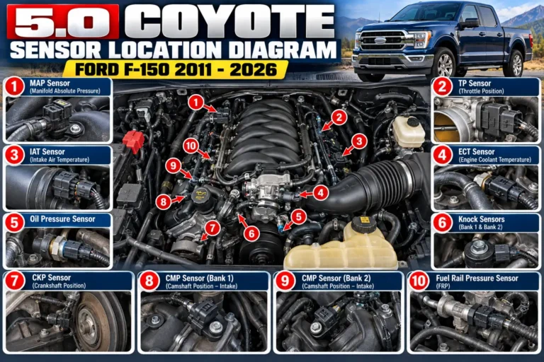
The 3.5 EcoBoost sensor location diagram starts with two easy landmarks: the manifold pressure sensor on the intake manifold and the charge-air pressure sensor on the pipework leading toward the throttle body.
Camshaft sensors sit farther back near the cylinder heads, while the crankshaft and oxygen sensors are reached from other areas of the engine and exhaust.
Connector positions depend on model year. This guide covers standard F-150 3.5L EcoBoost V6 engines, excluding the naturally aspirated V6, Raptor and PowerBoost hybrid.
How to Identify Your F-150 3.5 EcoBoost Engine
Recommended Best Deal Products


First, confirm the engine, not just the badge on the tailgate. Ford introduced a second-generation 3.5L EcoBoost in the 2017 F-150, so an illustration intended for a 2013 truck is not the right parts reference for a 2019 model.
| F-150 model years | Engine reference | Diagram to use |
|---|---|---|
| 2011–2016 | First-generation 3.5L EcoBoost | Early intake and timing sensor layout |
| 2017–2020 | Second-generation 3.5L EcoBoost | Updated pressure and temperature sensor terminology |
| 2021–2026 | Later standard 3.5L EcoBoost applications | Year- and VIN-specific Ford service layout |
Confirm the engine through its vehicle identification number (VIN) and underhood emissions label. Motorcraft technical resources provide access to service information and wiring diagrams. Ford lists standard, hybrid and high-output 3.5L variants separately for 2026.
For location work, front means the radiator end of the engine bay; rear means the firewall. Bank 1 is the passenger side of the engine on the standard F-150 3.5L EcoBoost; Bank 2 is the driver’s side.
2011 to 2016 F-150 3.5 EcoBoost Sensor Location Diagram
On first-generation trucks, the easiest pressure sensors to identify are on two different parts of the intake system. The manifold absolute pressure (MAP) sensor is on top of the intake manifold; the combined temperature and pressure sensor commonly called TMAP sits in the charge pipe ahead of the throttle body. The aFe installation instructions for the 2011 3.5L EcoBoost document both positions and caution that the connectors look similar.
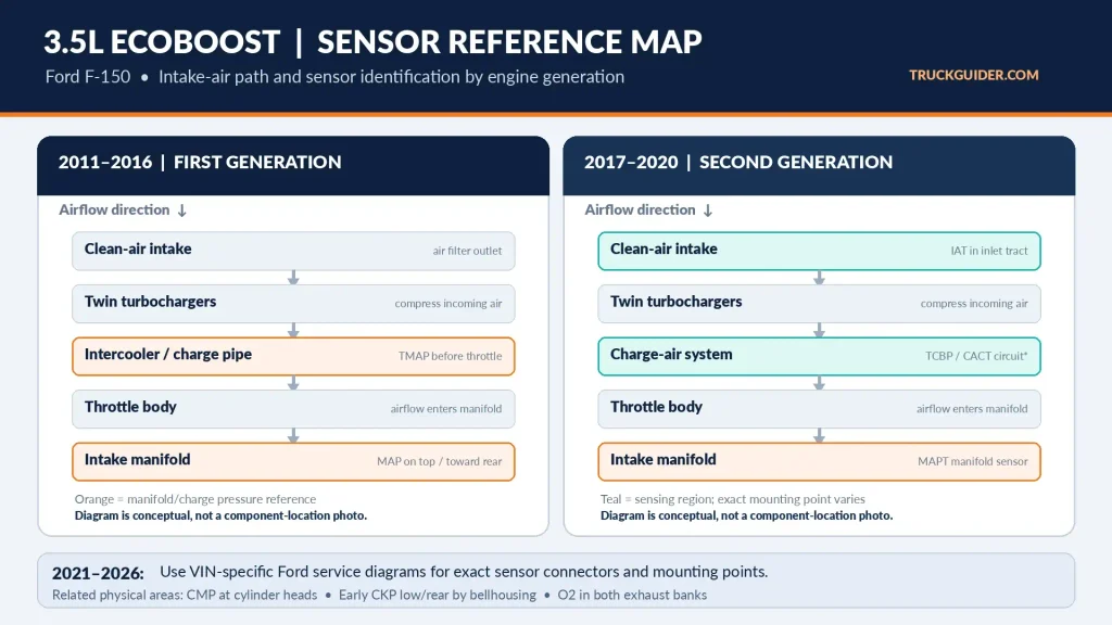
2011–2016 sensor orientation map
AIRFLOW PATH (conceptual, not to scale)
Air filter / clean-air pipe
          |
       Turbochargers
          |
     Intercooler (CAC)
          |
Charge pipe ---> TMAP pressure/temperature sensor
          |
      Throttle body
          |
 Intake manifold ---> MAP sensor (top of manifold)
          |
      Cylinder heads

OTHER AREAS
Rear of cylinder heads ---> Camshaft position sensors
Driver-side lower/rear engine ---> Crankshaft position sensor
Both exhaust banks ---> Upstream and downstream O2 sensors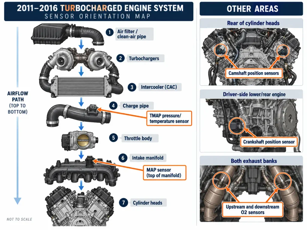
This map is not a scaled connector drawing. Remove the engine cover as directed, then inspect the manifold top and wiring harness.
The TMAP belongs to the pressurized charge pipe, not the clean-air tube. A separate intake air temperature (IAT) sensor is on the tubing near the air cleaner; TMAP also reports temperature.
2017 to 2020 F-150 3.5 EcoBoost Sensor Diagram
For 2017–2020 trucks, locate the intake manifold, charge-air path, and air-cleaner outlet before identifying a connector. The pressure and temperature components may be described using Ford-specific combinations, rather than the generic label “MAP sensor.”
2017–2020 sensor orientation map
AIRFLOW / COMPONENT REFERENCE (not to scale)
Air-cleaner outlet ---> IAT sensing area
          |
       Turbochargers
          |
 Charge-air system ---> TCBP / CACT sensing area
          |
       Throttle body
          |
 Intake manifold ---> MAPT sensor

Rear of both cylinder heads ---> CMP sensors
Exhaust path, both banks ---> O2 / catalyst-monitor sensors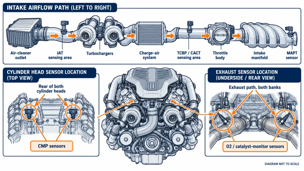
MAPT combines manifold pressure and temperature. TCBP/CACT combines turbocharger boost-pressure and charge-air temperature information. A 2017 F-150 labeled component reference distinguishes MAPT, TCBP/CACT, IAT and crankcase-pressure sensors. Confirm the final connector position by VIN.
Trace the pipe or manifold each sensor enters. Similar-looking sensors are not necessarily interchangeable.
What Changes on 2021 to 2026 EcoBoost F-150s
The same major sensor functions remain relevant on newer standard 3.5L EcoBoost trucks: manifold pressure and temperature, charge-air pressure and temperature, intake-air temperature, camshaft position, crankshaft position, and exhaust oxygen feedback. What changes is the correct service illustration, wiring connection, part number, and sometimes the physical arrangement.
For a 2021–2026 F-150, use this identification sequence rather than assuming a 2017 diagram is exact:
| Sensor you need | First area to inspect | What confirms the exact position |
|---|---|---|
| MAPT | Intake manifold | VIN-specific component illustration |
| TCBP or charge-air sensor | Turbocharger/charge-air plumbing | Ford sensor name and connector diagram |
| IAT | Fresh-air inlet tract | Year-specific intake-system diagram |
| CMP or CKP | Cylinder-head or lower-engine region | Engine-specific workshop illustration |
| O2 | Exhaust before or after the catalyst | Bank and sensor number in the service record |
The 2026 Ford F-150 owner’s manual confirms the standard 3.5L EcoBoost configuration, but an engine-specific repair diagram is necessary for precise connector positions. Do not assume every newer boost-pressure sensor is beside the throttle body.
Where Are the Main 3.5 EcoBoost Pressure Sensors
The difference between manifold pressure and charge-pipe pressure explains why several similar sensors appear in one engine bay. They monitor different points along the intake path.
Manifold Pressure Sensor
The MAP, or MAPT when temperature sensing is included, measures pressure in the intake manifold after the throttle body. On the first-generation F-150 3.5L EcoBoost, look on top of the intake manifold underneath or near the engine cover. On the second-generation engine, identify the manifold-mounted MAPT using the applicable Ford drawing.
If the connector is on the pressurized pipe before the throttle body, it is not the manifold-mounted sensor. That distinction matters when following a fault code or ordering a component.
Charge Air Pressure Sensor
Early engines use a charge-pipe TMAP reference. Later Ford documentation may name a sensor TCBP, CACT, or a combined TCBP/CACT device. Those terms describe boost pressure and charge-air temperature measurements, but the exact sensor design and mounting point vary by configuration.
Follow the intake route from the intercooler toward the throttle body, then confirm the sensor’s name against the wiring diagram. On later trucks, also inspect the turbocharger area if the vehicle-specific drawing identifies TCBP there.
Intake Air Temperature Sensor
The IAT reports incoming air temperature. In a typical non-MAF 3.5L EcoBoost intake layout, the air-inlet temperature sensor is on the clean-air tube near the air cleaner, while other temperature readings can be integrated with manifold or charge-air pressure sensors.
The standard 3.5L EcoBoost uses a speed-density strategy rather than the conventional hot-wire MAF arrangement found on many other engines. This distinction is explained further in TruckGuider’s MAF versus MAP sensor location guide. Do not search for a removable MAF sensor simply because a generic F-150 parts diagram shows one.
Where Are the 3.5 EcoBoost Camshaft and Crankshaft Sensors
The camshaft and crankshaft position sensors are not in the upper intake piping. They monitor rotating engine components and are harder to access than the MAP sensor.
Camshaft Position Sensors
On the 2016 3.5L EcoBoost, the camshaft position (CMP) sensors are located at the rear of the cylinder heads, near the firewall. A 2016 F-150 diagnostic diagram discussion identifies this area, and 2017–2020 repair discussions also describe rear-of-head access.
There are intake and exhaust camshaft position signals on each bank. Diagnostic descriptions generally use A for intake and B for exhaust. Bank 1 is the passenger side; Bank 2 is the driver’s side. Confirm which connector is A or B against the service diagram before removing either sensor.
A CMP sensor is not the same part as a cam phaser or variable cam timing (VCT) oil-control solenoid. Those components can affect cam timing without a failed sensor. TruckGuider’s 3.5 EcoBoost cam phaser replacement guide covers the mechanical repair topic separately.
Crankshaft Position Sensor
On 2013–2016 first-generation F-150 3.5L EcoBoost engines, look low on the driver’s side at the rear of the engine, close to the transmission bellhousing and flywheel/reluctor area. This is not a sensor beside the front crankshaft pulley. A 2013 F-150 illustrated repair answer describes access through the driver’s wheel well or from underneath; the 2016 repair reference places the sensor near the torque-converter access area.
A shield, liner or bracket may block access. Support the truck securely when working underneath. Verify 2017-and-newer CKP positions using their own service drawings.
Where Are the Ford F-150 EcoBoost Oxygen Sensors
The standard F-150 3.5L EcoBoost has oxygen/air-fuel feedback on both exhaust banks. For the 2017–2021 applications covered in this oxygen sensor location reference, the arrangement includes an upstream and downstream sensor on each bank.
| O2 sensor designation | Side of engine | Where to look |
|---|---|---|
| Bank 1 Sensor 1 | Passenger side | Upstream, before the catalytic converter |
| Bank 1 Sensor 2 | Passenger side | Downstream, after the catalytic converter |
| Bank 2 Sensor 1 | Driver’s side | Upstream, before the catalytic converter |
| Bank 2 Sensor 2 | Driver’s side | Downstream, after the catalytic converter |
“Sensor 1” does not mean the sensor closest to the front bumper. It means upstream of that bank’s catalytic converter. “Sensor 2” is downstream of it. The upstream sensor may be called an air-fuel ratio sensor in service information.
Exhaust components remain hot long after shutdown. Let the system cool fully before inspection, and use the VIN to verify the exact replacement part and connector orientation.
How to Identify EcoBoost Sensors in 5 Steps
Finding a connector is only the first part of identifying the correct sensor. A similar-looking sensor on another pipe may have an entirely different function.
- Confirm the engine and year. Check the VIN, model year, and engine designation. Do not use a 2.7L EcoBoost or naturally aspirated 3.5L diagram for this engine.
- Orient the engine bay. Face the truck from the grille. The radiator is in front; the firewall is at the rear. Identify the air cleaner, throttle body, intake manifold, and cylinder heads.
- Go to the correct system. For MAP or MAPT, inspect the intake manifold. For TMAP or boost-pressure sensing, trace the charge-air route. For CMP, inspect the rear of the heads. For CKP, use the appropriate lower-engine access instructions. For O2, follow the correct exhaust bank.
- Check the connector without forcing it. Compare mounting location, wiring route, and connector shape with the service illustration. Do not pry on clips or pull the wires.
- Verify before replacing. Read the diagnostic trouble code, inspect wiring and hoses, and match the Ford part number using the VIN. A code does not necessarily prove sensor failure.
Work with the ignition off and engine cool when inspecting connectors. Keep hands and tools clear of moving belts, turbocharger plumbing, and hot exhaust parts. Leave fuel-system components untouched unless following the Ford service procedure.
5 Common 3.5 EcoBoost Sensor Codes to Check
A code reader helps identify which system to inspect, but it cannot establish that the sensor itself has failed. Use the complete code definition and the vehicle’s diagnostic procedure.
| Example code | System indicated | First area to inspect |
|---|---|---|
| P0106 | MAP/BARO pressure range or performance | Manifold sensor, connector, air/vacuum leaks |
| P0236 | Turbocharger boost sensor range or performance | Charge-air pressure sensing and plumbing |
| P0340 | Camshaft position sensor A circuit | CMP connector, wiring, signal and timing context |
| P0335 | Crankshaft position sensor A circuit | CKP connector, wiring and crank signal |
| P0135 | Oxygen sensor heater circuit, Bank 1 Sensor 1 | Passenger-side upstream O2 heater wiring and sensor circuit |
P0016 is a crankshaft-to-camshaft correlation code, not proof of a faulty CKP sensor. Ford TSB 17-0026 addresses timing-chain wear on certain 2011–2014 3.5L EcoBoost trucks with P0016. Ford TSB 23-2143 describes cold-start cam phaser rattle in certain 2017–2020 trucks. This later bulletin is marked superseded or deactivated; consult the latest VIN-specific procedure.
TruckGuider also covers F-150 timing chain replacement and related diagnostics. For correlation codes, check wiring and actual versus commanded cam timing before buying sensors.
How to Confirm the Correct 3.5 EcoBoost Sensor
The safest way to use a 3.5 EcoBoost sensor location diagram is to identify your F-150 engine first, then trace the physical system the sensor measures. Start with the manifold for MAP or MAPT, the charge-air system for boost sensing, the rear of the cylinder heads for camshaft sensors, and the exhaust banks for oxygen sensors. Earlier first-generation trucks place the crankshaft sensor low at the rear of the engine.
Use the year-specific Ford service diagram for the final connector and part-number check, particularly on 2021–2026 models. If a trouble code led you to the sensor, diagnose the circuit and connected system before replacing parts. The correct location gets you to the right component; the diagnostic test tells you whether it needs replacement.
Ford F-150 3.5 EcoBoost Sensor Location FAQs
Where Is the MAP Sensor on a 3.5 EcoBoost F-150?
On first-generation 2011–2016 F-150 3.5L EcoBoost engines, the MAP sensor is on top of the intake manifold and may be concealed by the engine cover. Later engines can use the combined MAPT designation. Find the manifold first, then confirm the connector with your year-specific drawing.
Does the Ford 3.5 EcoBoost Have a MAF Sensor?
The standard F-150 3.5L EcoBoost applications discussed here use a speed-density air-measurement strategy, with manifold pressure and intake-air temperature information rather than the conventional removable hot-wire MAF sensor. Do not assume generic F-150 MAF instructions apply. Confirm the sensor type for your engine and model year.
Where Is the Crankshaft Sensor on a 2016 F-150 EcoBoost?
On the 2016 3.5L EcoBoost, the crankshaft position sensor is low on the driver’s side near the rear engine and transmission bellhousing area. The access point may require removing an obstruction such as a shield or bracket. Verify the exact procedure before working underneath the truck.
Are the 2016 and 2018 EcoBoost Sensor Locations the Same?
No universal location diagram should be used for both years. The 2016 F-150 has the earlier 3.5L EcoBoost generation, while the 2018 uses the second-generation engine. Several sensors perform similar jobs, but connector, naming and mounting details must be checked against the correct Ford service illustration.
Where Are Bank 1 and Bank 2 O2 Sensors on a 3.5 EcoBoost?
Bank 1 is the passenger-side exhaust path and Bank 2 is the driver’s side on the standard F-150 3.5L EcoBoost. Sensor 1 is upstream of that bank’s catalytic converter; Sensor 2 is downstream. Confirm the year-specific part and connector before ordering a replacement.
To pick up a draggable item, press the space bar. While dragging, use the arrow keys to move the item. Press space again to drop the item in its new position, or press escape to cancel.
To pick up a draggable item, press the space bar. While dragging, use the arrow keys to move the item. Press space again to drop the item in its new position, or press escape to cancel.