5.0 Coyote Sensor Location Diagram: 2011-2026 Ford F-150

Quick Answer: The 5.0 Coyote has four cam sensors at the back of the cylinder heads and two knock sensors under the intake manifold. Oxygen sensors use B1S1 to B2S2 names, with bank 1 on the passenger side. Crankshaft position, intake air temperature, manifold pressure, and cylinder head temperature sensors need a service manual check.
A 5.0 Coyote sensor location diagram helps you find the right sensor before you pull a part or buy a replacement. This guide maps the Coyote sensors that our sources confirm, using Ford Performance, Haltech, and fitment documents.
The diagram below places camshaft, knock, oxygen, oil pressure, fuel rail pressure, and mass airflow sensors. It leaves four sensors off the drawing because we could not confirm their positions. Those are crankshaft position, intake air temperature, manifold pressure, and cylinder head temperature.
Not sure which Coyote you have? Start with our 5.0 Coyote specs guide for generations and model years.
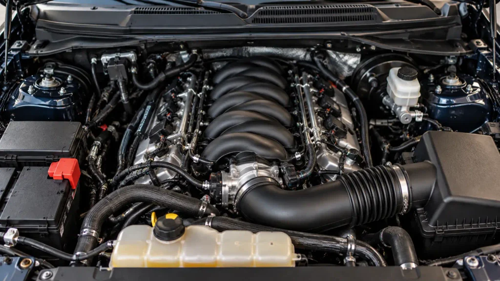
5.0 Coyote Sensor Location Diagram by Engine Zone
Recommended Best Deal Products

The schematic below is a top-down layout with the engine front at the top. Left and right follow the driver’s seat view. It shows zones only, so use it to find the area before you look for the part.
5.0 Coyote Sensor Zones, Top-Down View
Engine front at top. Zones only, not exact measurements.
- 1Camshaft position sensors (4), rear of the cylinder heads
- 2Knock sensors (2), valley under the intake manifold
- 3Upstream oxygen sensors B1S1 and B2S1, before the catalytic converters
- 4Downstream oxygen sensors B1S2 and B2S2, after the catalytic converters
- 5Oil pressure sender, left front of the block
- 6Fuel rail pressure sensor, back left end of the rail (Gen 3)
- 7Mass airflow sensor, integral to the air cleaner assembly
Not drawn: crankshaft position, intake air temperature, manifold pressure and cylinder head temperature sensors. Confirm those in Ford’s service manual.
The table repeats each confirmed sensor with its count, position, and the source behind it.
| Sensor | Count | Where It Sits | Source Basis |
|---|---|---|---|
| Camshaft position | 4 | Back of each cylinder head | Haltech knowledge base |
| Knock | 2 | Pedestals in the valley under the intake manifold | s197forum thread |
| Oxygen, 2018 to 2020 F-150 | 4 | B1 on the passenger side, B2 on the driver side | Go-Parts listing |
| Oil pressure sender | 1 | Left front of the block | Factory Five Gen 3 sheet |
| Fuel rail pressure, Gen 3 | 1 | Back left end of the direct injection rail | Factory Five Gen 3 sheet |
| Mass airflow | 1 | Integral to the air cleaner assembly | Ford Performance sheet |
Which Coyote Generations Our Sources Cover
The Coyote runs from 2011 to 2026 in four generations, and Gen 3 added direct injection alongside port injection. Our sources do not cover every generation equally, so the table shows what each one backs up.
| Generation | Years | What Our Sources Cover |
|---|---|---|
| Gen 1 | 2011 to 2014 | Ford Performance control pack sheet: wideband sensors and mass airflow |
| Gen 2 | 2015 to 2017 | General Coyote layout only |
| Gen 3 | 2018 to 2020 | Factory Five fitment sheet and Go-Parts oxygen sensor listing |
| Gen 4 | 2021 to 2026 | General Coyote layout only |
Where a source covers one generation, we say so in the text. Check your engine with our F-150 VIN engine code chart before you order parts.
5.0 Coyote Camshaft Position Sensor Locations
Haltech’s Coyote engine article lists four camshaft position sensors, one for each camshaft. They sit at the back of each cylinder head.
That gives two sensors per bank, one for the intake cam and one for the exhaust cam. Read the code with a scan tool first, because cam sensor codes point to a bank before you choose a side.
5.0 Coyote Knock Sensor Location Under the Intake
The Coyote has two knock sensors. A s197forum thread on the sensors places them on pedestals in the engine valley, under the intake manifold.
The passenger-side connector sits toward the rear of the valley. Both sensors sit beneath the manifold, so reaching them means removing the manifold first.
That access makes knock sensor jobs labor heavy. It is a strong reason to test the circuit before you order parts.
5.0 Coyote Oxygen Sensor Locations on the F-150
Go-Parts lists four oxygen sensors on the 2018 to 2020 F-150 5.0. They are B1S1 and B1S2 on the passenger side, and B2S1 and B2S2 on the driver side.
In each name, B is the bank and S is the position. S1 sits before the catalytic converter and S2 sits after it. Bank 1 is the passenger side on this engine.
Ford Performance’s control pack sheet for the 2011 to 2014 engine lists two wideband UEGO sensors, one right and one left. If you relocate them, the sheet says to sample from cylinder 4 on bank 1 and cylinder 7 on bank 2.
For the wider F-150 lineup, read our F-150 oxygen sensor location diagram.
Other Coyote Sensors with Confirmed Locations
Mass Airflow Sensor
The Ford Performance sheet lists the mass airflow sensor as integral to the air cleaner assembly. That sheet covers 2011 to 2014 engines, so confirm the setup on later trucks.
Oil Pressure Sender
Factory Five’s Gen 3 fitment sheet places the stock oil pressure sender at the left front of the block.
A low reading does not always mean a bad sender. Check the oil level first.
Fuel Rail Pressure Sensor on Gen 3
The same fitment sheet places the fuel rail pressure sensor at the back left end of the direct injection rail. Direct injection arrived with Gen 3, so earlier engines do not have this sensor.
Coyote Sensors You Should Confirm in the Service Manual
We could not verify where four sensors sit. They are the crankshaft position sensor, the intake air temperature sensor, the manifold pressure sensor, and the cylinder head temperature sensors.
Published sources conflict on the crankshaft position sensor, so we left it off the drawing. The Ford Performance sheet lists two cylinder head temperature sensors, but we found no source for their exact positions.
For these four, use Ford’s service manual or a VIN-specific wiring diagram for your model year and trim. A parts-store diagram built for another year can send you to the wrong spot.
How to Diagnose a Failing Coyote Sensor Before Replacing It
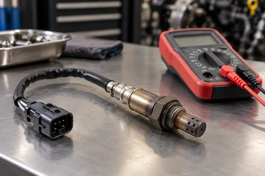
Confirm the fault before you buy a part. Read the code with a scan tool, then note the bank and sensor position it names.
Next, check the connector and harness for chafing, corrosion, or a loose pin. Then compare live data on the scan tool with what the engine is doing.
A reading that stays flat or jumps to an extreme value often points to wiring or the module, not the sensor. Replace the sensor only after the circuit checks out.
Using the 5.0 Coyote Sensor Location Diagram
Use this 5.0 Coyote sensor location diagram as a map of the sensors we could confirm. The Coyote has four cam sensors at the back of the cylinder heads and two knock sensors under the intake manifold. Oxygen sensors follow the B1S1 to B2S2 naming, with bank 1 on the passenger side.
Oil pressure, fuel rail pressure, and mass airflow sensors have sourced positions too, but some of those sources cover only one generation. Crankshaft position, intake air temperature, manifold pressure, and cylinder head temperature sensors need a service manual check for your year. Confirm your engine with the VIN, then test the circuit before you replace anything.
Frequently Asked Questions About Coyote Sensor Locations
How Many Cam Sensors Does It Have
The Coyote has four camshaft position sensors, one for each camshaft. Haltech’s engine article places them at the back of each cylinder head, which gives two sensors per bank.
Where Are the Coyote Knock Sensors
The Coyote has two knock sensors on pedestals in the valley under the intake manifold. The passenger-side connector sits toward the rear. Plan to remove the manifold to reach either one.
How Many Oxygen Sensors Does It Have
Go-Parts lists four on the 2018 to 2020 F-150 5.0. They are B1S1 and B1S2 on the passenger side, and B2S1 and B2S2 on the driver side. Confirm the count for other model years before ordering.
Where Is the Crankshaft Position Sensor
We could not confirm it, because published sources conflict. Check Ford’s service manual for your model year before you crawl under the truck. We left it off the diagram on purpose rather than guess.
Where Is the Coyote MAF Sensor
Ford Performance’s control pack sheet for the 2011 to 2014 engine lists the mass airflow sensor as integral to the air cleaner assembly. Confirm the setup on later trucks, since that sheet does not cover them.


![Ram 1500 5.7L Hemi Oil Filter Guide [2026]](https://truckguider.com/wp-content/uploads/2026/03/ram-1500-5-7-oil-filter-featured.webp)