2011 Chevy Silverado Wiring Diagram: Wiring & Maintenance 2026

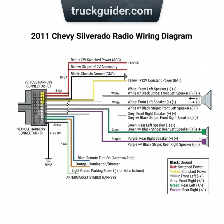
The 2011 Chevy Silverado electrical system routes through the underhood fuse block and the Body Control Module under the driver dash. Primary constant 12V hot wire circuits are heavy-gauge Red or Red/Black, while system chassis ground wire circuits are solid Black. Critical exterior and trailer pin assignments interface at the rear chassis junction block.
📌 Key Takeaways
- Main battery feeds use 10 AWG to 8 AWG Red/Black hot wire leads protected by high-amperage Maxi-fuses.
- Body Control Module (BCM) connectors X1 through X7 handle logic-level switching, requiring precise pin assignment verification.
- Chassis ground points (G100 to G401) require clean metal contact with 9 Nm (80 lb-in) torque specs.
- The most frequent electrical fault stems from oxidized ground terminals along the driver-side frame rail.
- Perform basic 12V continuity tests yourself, but consult an ASE specialist for high-speed GMLAN data bus diagnostics.
Navigating the electrical architecture of the 2011 Chevrolet Silverado (GMT900 platform, covering 1500, 2500HD, and 3500HD models) requires an exact understanding of General Motors’ distributed power distribution and multiplexed serial data networks. Modern full-size trucks integrate mission-critical body, chassis, and powertrain circuits across high-speed and low-speed controller area networks (CAN). Utilizing the factory 2011 chevy silverado wiring diagram ensures that technicians, mechanics, and upfitters avoid induced harness damage, parasitic battery drains, and control module degradation. This technical documentation provides the schematics, pin assignment charts, terminal block layouts, and wire color code standards essential for comprehensive repair and precise upfitting.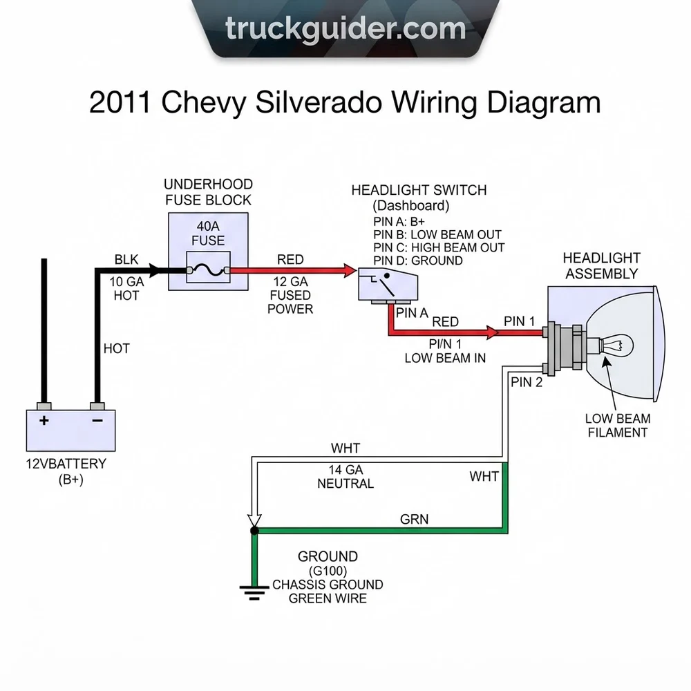
2011 Chevy Silverado Wiring Diagram: Power Distribution and Module Architecture


The electrical backbone of the 2011 Silverado relies on an interconnected network of power distribution centers and logic modules designed to segment high-amperage current delivery from sensitive microprocessor logic. At the core of the system sits the Underhood Fuse Block (designated X50A in OEM service manuals), situated on the driver-side inner wheel apron. This primary power distribution center handles raw battery voltage distributed through high-capacity bus bars from the primary battery hot wire. It routes fused power directly to high-draw consumers, including the starter motor solenoid, cooling fan relays, and glow plug modules on Duramax diesel applications, while simultaneously energizing the downstream passenger-cabin distribution blocks.



The Underhood Fuse Block distributes current to the Instrument Panel (IP) Fuse Block (X51A and X51L), mounted behind the removable driver-side dashboard end-cap. The IP fuse block manages lower-amperage branch circuits ranging from 5 to 30 amperes, guarding the instrument cluster, climate control head, cabin blowers, and secondary logic lines. Connected in series with the cabin architecture is the Body Control Module (BCM), situated directly beneath the driver-side dashboard assembly above the brake pedal sweep. The BCM acts as both a solid-state switching gateway and an electronic relay controller, managing vehicle lighting, perimeter security, passive anti-theft (Passlock/PASS-Key III+), and Retained Accessory Power (RAP) circuits.
On GMT900 platforms, the BCM controls relays via low-side switching (providing a ground wire path) rather than outputting 12-volt battery power. When referencing your 2011 chevy silverado wiring diagram for switched accessories, confirm whether the schematic illustrates high-side power delivery or BCM micro-controlled pull-down paths.
Powertrain operational management resides in the Engine Control Module (ECM—typically the E38 for 4.8L, 5.3L, and 6.2L V8 gas engines, E67 for specialized variants, or E86 for the 6.6L LML Duramax) paired with the T42 or T43 Transmission Control Module. These powertrain modules interface through the high-speed GMLAN serial data bus, operating at 500 kbps across an unshielded twisted pair (designated Circuit 2500 Tan and Circuit 2501 Tan/Black). The low-speed GMLAN operates on a single-wire configuration (SWCAN, Circuit 5060 Dark Green) at 33.3 kbps to control comfort, door, and dashboard electronics. Proper schematic analysis demands absolute isolation between these communication conductors and any non-OEM analog wiring to prevent serial communication freeze conditions.
2011 Silverado Wire Color Code and Terminal Pin Assignment Chart


General Motors standardizes harness fabrication using cross-linked polyethylene (XLPE) insulated wire identified by three primary attributes: metric conductor cross-sectional gauge (expressed in square millimeters, where 0.5 mm² corresponds roughly to 20 AWG and 0.8 mm² corresponds to 18 AWG), basic insulation color, and an optional tracer/stripe color. Wiring schematics published in the ACDelco Technical Delivery System (TDS) associate every physical conductor with a proprietary four-digit circuit number. Pinouts must be identified from the terminal face or wire-entry side of each modular connector housing, referenced by GM harness cavity numbering or alpha-numeric coordinates.
GM Service Information specifies that standard low-voltage multi-pin terminal blocks utilize Metri-Pack 150/280 and GT 150 series pins. Never probe directly into the terminal female spring-leaf contact; always utilize the appropriate J-35616 test probe adapter to prevent terminal spread and intermittent open-circuit faults.
The Data Link Connector (DLC / OBD-II Port X84) provides direct diagnostic and physical interface access to the primary networks. The following chart details the factory pin assignment and wire color code layout at the DLC beneath the driver-side lower knee bolster:


| Pin Assignment | Circuit # | Wire Color Code | Conductor Gauge | Functional Description & Voltage |
|---|---|---|---|---|
| Pin 1 | 5060 | Dark Green | 0.35 mm² (22 AWG) | Low-Speed GMLAN (Single-Wire CAN, 0–4V variable) |
| Pin 4 | 150 | Black | 0.5 mm² (20 AWG) | Chassis Ground Wire (0.0V reference to frame) |
| Pin 5 | 451 | Black/White | 0.5 mm² (20 AWG) | Signal Ground Wire (Clean logic ground, 0.0V) |
| Pin 6 | 2500 | Tan | 0.35 mm² (22 AWG) | High-Speed GMLAN Bus (+) (2.5V–3.5V dominant) |
| Pin 14 | 2501 | Tan/Black | 0.35 mm² (22 AWG) | High-Speed GMLAN Bus (-) (1.5V–2.5V dominant) |
| Pin 16 | 40 | Orange | 0.8 mm² (18 AWG) | Unswitched Hot Wire (B+ Constant, 12.0V–14.4V) |
For fleet maintenance, trailer brake retrofit, or lighting diagnostics, the rear bumper 7-pin RV round electrical socket (Connector X430) uses heavy-gauge trunking tied into the factory trailering package (Z82 option). The 2011 chevy silverado wiring diagram establishes the pin assignments and metric gauge specs below:
| Terminal Cavity | Circuit # | Conductor Color | Gauge Metric / AWG | Terminal Function & Circuit Limits |
|---|---|---|---|---|
| Cavity 1 | 1150 | White | 5.0 mm² (10 AWG) | Main Return Ground Wire (chassis attached to G401) |
| Cavity 2 | 47 | Dark Blue | 3.0 mm² (12 AWG) | Electric Trailer Brakes (0–12V pulse-width modulated) |
| Cavity 3 | 2109 | Brown | 2.0 mm² (14 AWG) | Park / Running Lamps (Fused hot wire from park lamp relay) |
| Cavity 4 | 742 | Red/Black | 5.0 mm² (10 AWG) | Fused Battery 12V Hot Wire (Auxiliary charge, 40A fused) |
| Cavity 5 | 1618 | Yellow | 1.0 mm² (16 AWG) | Left Stop / Turn Lamp Circuit (12V switched pulsed) |
| Cavity 6 | 1619 | Dark Green | 1.0 mm² (16 AWG) | Right Stop / Turn Lamp Circuit (12V switched pulsed) |
| Cavity 7 | 1624 | Light Green | 1.0 mm² (16 AWG) | Backup / Reverse Signal (12V switched at transmission reverse) |
Connecting Accessories Using the 2011 Chevy Silverado Wiring Diagram


Splicing into random harness looms on a 2011 Silverado risks corrupting GMLAN communication, overloading solid-state drivers in the BCM, or triggering unwanted diagnostic trouble codes (DTCs). When integrating add-on components like auxiliary off-road lights, high-output audio, fleet tracking, or inverters, follow this sequence using factory-engineered tap junctions.
- Locate the Mid-Bus Electrical Center (MBEC): Disregard splicing into the steering column harness. Locate the MBEC terminal block (Connector X14) positioned directly to the left of the driver foot-brake pedal mechanism under a black protective shroud. This terminal block is engineered explicitly by GM as an upfitter and option breakout center.
- Identify Desired Power and Control Signals: Reference the MBEC pinout. Cavity 7 (Circuit 2440, Dark Green wire, 0.5 mm²) provides a clean 12-volt low-current feed driven by the vehicle’s Retained Accessory Power (RAP) circuit. This keeps devices powered after ignition-off until a cab door opens. Cavity 5 and Cavity 6 deliver unswitched hot wire battery feeds (Circuit 442, Red/White, protected by a 30-amp circuit breaker in the IP block). Cavity 8 provides a direct body ground wire (Circuit 150, Black).
- Isolate Switched Loads Using Snubber Relays: Never command high-current loads directly through factory switches or the BCM. Route the MBEC trigger line to Pin 86 of an external automotive relay. Install a flyback suppression diode (such as a 1N4004) across Pin 86 and Pin 85 (cathode band toward Pin 86 power) to collapse high-voltage inductive spikes that can flash back into BCM logic tables and fry microprocessor outputs.
- Draw Primary Current from the Underhood Power Studs: For external loads exceeding 15 amperes, draw current directly from Stud 1 or Stud 2 located on the forward-facing edge of the Underhood Fuse Block. Stud 1 is protected by the primary battery bus and can handle up to 40 amps using a heavy-gauge cable (minimum 8 AWG / 8.0 mm²). Fasten heavy ring terminals with an M8 x 1.25 nut torqued to exactly 9 N·m (80 lb-in) to prevent high-resistance thermal junctions.
- Secure and Route Downstream Cabling: Route aftermarket looms through the main firewall rubber grommet pass-through located high and to the left of the brake booster. Never puncture bare metal edges without a continuous neoprene or rubber firewall grommet. Verify that aftermarket routing maintains at least 150 mm (6 inches) of clearance from unshielded secondary ignition components (spark plug leads and coils) to prevent electromagnetic interference (EMI) injection into the Silverado’s serial lines.
Do not use standard tap connectors (Scotchlok-style) to puncture wires within the 2011 Silverado electrical harness. Piercing the insulation invites copper strand oxidation, alters high-speed bus impedance, and invalidates circuit resistance tolerances required for BCM bulb-out detection and airbag monitoring.
For equipment requiring integration with the trailer brake setup, review our technical guide on Silverado trailer brake controller wiring installation to match OEM brake switch pulse signals without disturbing the ABS module.


Diagnosing 2011 Silverado Ground Wire Faults and Network Failures



Intermittent electrical phenomena on the 2011 Silverado—including flashing instrument needles, false “Service StabiliTrak” alerts, door lock chattering while driving, and crank/no-start conditions—typically stem from ground loop variance or degraded frame grounding points rather than defective microprocessors. On the GMT900 platform, differential grounds must maintain less than 0.100V (100 mV) drop between reference points under loaded operating conditions.
Four primary chassis ground locations (G-series points) require direct physical inspection and mechanical cleaning whenever erratic electrical symptoms manifest:
- G102 and G103 Engine Grounds: Mounted to the lower right and left sides of the engine block toward the front accessories. These ring eyelets ground the primary ignition coils, knock sensors, and critical ECM/TCM references. Oil contamination or loose mounting bolts induce sensor cross-talk and DTCs P0300 through P0308.
- G100 and G101 Cab-to-Frame Bonding Points: Located on the driver-side frame rail directly below the driver footwell and near the radiator support core. A flat, braided copper ground wire bonds the isolated cab body to the frame. Road salt and galvanic corrosion at this point induce phantom instrument cluster shutoffs and erratic illumination. For deeper dash-related issues, consult our walkthrough on GMT900 instrument cluster repair guide.
- G200 and G201 Cab A-Pillar Grounds: Situated behind the interior plastic kick panels at the base of both the left and right A-pillars. These terminals serve as the primary logic and ground wire landing for the BCM, instrument panel, and steering wheel control modules. Retorque the 10mm head ground bolts to 9 N·m (80 lb-in).
- G401 Rear Frame Ground: Fastened to the crossmember directly above or rearward of the spare tire hoist. This single point carries the return current for the entire rear lighting harness and the chassis-mounted Fuel Pump Driver Module (FPDM). A corroded G401 eyelet causes the FPDM to lose reference voltage, setting DTC P069E or P0230, which starves the fuel rail and yields an engine stall under load. See our dedicated analysis on GM fuel pump driver module bypass and diagnosis for bench testing pinouts.
When tracking an active network breakdown where scan tools report “U” class trouble codes (such as U0100 Lost Communication with ECM or U0101 Lost Communication with TCM), perform a bus termination resistance check. Turn the ignition off, extract the key, wait 10 minutes for all sleep cycles to settle, and connect a calibrated Digital Multimeter (DMM) set to the 200-ohm scale across DLC Pin 6 (CAN-H) and Pin 14 (CAN-L).
The 2011 Silverado high-speed CAN system relies on two parallel 120-ohm terminating resistors: one integrated internally within the Engine Control Module (ECM) and the second positioned at the extreme end of the chassis backbone harness (near the rear axle or inside the BCM, depending on wheelbase and RPO options). An undamaged, fully intact bus reads precisely 60 ohms nominal (58 to 62 ohms acceptable). If your DMM indicates 120 ohms, one terminating resistor or harness branch is open-circuited. A reading of 0 to 10 ohms signifies a short circuit between the Tan and Tan/Black data lines. An infinite or mega-ohm reading confirms a total open circuit across both bus leads forward of the DLC junction.


Frequently Asked 2011 Chevy Silverado Wiring Diagram Questions
Where can I find the 12V Retained Accessory Power (RAP) wire on a 2011 Silverado?


The factory 12V Retained Accessory Power feed is accessible at the Mid-Bus Electrical Center (MBEC Connector X14) located beneath the dashboard to the left of the brake pedal assembly. Target Cavity 7, which hosts Circuit 2440 (0.5 mm² Dark Green wire). This circuit provides low-current 12-volt hot wire power whenever the ignition is in the RUN or ACC positions, continuing after key removal until a front door is cycled. Use this wire solely to trigger an auxiliary relay coil rather than running high-current loads directly.
What is the terminating resistance specification for the 2011 Silverado CAN bus?
According to factory GM service engineering specs, the nominal terminating resistance of the high-speed GMLAN data bus is 60 ohms. This can be verified by placing a digital multimeter set to ohms across Pin 6 (CAN High, Tan) and Pin 14 (CAN Low, Tan/Black) on the Data Link Connector under the steering column with the vehicle battery disconnected. The 60-ohm measurement results from two 120-ohm internal terminating resistors wired in parallel across the extremities of the network architecture.
Why does my 2011 Silverado show “Service 4WD” and flashing cluster gauges?
This symptom indicates a momentary voltage drop or loss of ground reference on the G100 frame ground (driver-side forward frame rail) or the G200 A-pillar logic ground, rather than a failure of the four-wheel-drive transfer case actuator. When the ground connection oxidizes, the BCM and Transfer Case Control Module (TCCM) lose differential reference voltage, corrupting serial communication over the high-speed bus and dropping gauge communication off the network.
What wire color code does GM use for switched ignition on the 2011 Silverado?


Switched Ignition (IGN 1 / Run-Crank voltage) across the cabin harnesses is routed primarily via Circuit 439, which uses a 0.5 mm² or 0.8 mm² Pink wire. The primary constant unswitched battery hot wire uses Circuit 40 (Orange). Before connecting equipment, verify circuit behaviour with a multimeter: Circuit 439 should read 0.0 volts when the key is OFF, and register full battery operating voltage (12.4V–14.4V) in both the RUN and CRANK positions.
Which wire gauge is required when tapping into the underhood fuse block battery studs?
If utilizing Stud 1 (the forward-most 8mm post on the front face of the Underhood Fuse Block) for auxiliary high-draw loads, you must match the terminal fuse rating. If using a 30A or 40A Maxi-fuse or JCase fuse in that cavity, use a minimum cross-sectional wire gauge of 10 AWG (5.0 mm²) copper stranded conductor. For continuous loads approaching 50A, upgrade to 8 AWG (8.0 mm²) wire rated for engine-bay temperatures (-40°C to 125°C) to prevent thermal degradation and voltage drop across the line.
Step-by-Step Guide to Understanding the 2011 Chevy Silverado Wiring Diagram
Identify – Disconnect negative battery terminal and identify the target circuit using the factory schematic.
Locate – Find the corresponding junction connector or module location using harness routing callouts.
Reference – Match each wire color code, stripe tracer, and pin assignment cavity label on the connector face.
Connect/Route – Terminate replacement wiring with weather-pack crimps, heat shrink, and original harness loom protection.
Verify – Reconnect battery power and verify circuit voltage, continuity, and ground integrity using a digital multimeter.
Troubleshoot – If circuit behaves erratically, trace back to main frame grounds and check related mini-fuses for resistance.