2014 Ram 1500 Fuse Box Location & Diagram: The Definitive TIPM Guide
The Electrical Nervous System of the 4th Generation Ram
The 2014 Ram 1500 represents a significant milestone in the lineage of American pickup trucks. As part of the DS platform (4th generation), this model year sat at the intersection of traditional mechanical robustness and the burgeoning era of computerized vehicle control. Unlike its predecessors from the 1990s, where electricity was primarily used to spark plugs and light bulbs, the 2014 Ram 1500 utilizes electricity as its primary language of control. Every system, from the transmission shift points to the variable displacement “Eco Mode” of the Hemi V8, is orchestrated by silicon and software.
At the heart of this complex network lies a component that has become legendary among mechanics and owners alike, often for the wrong reasons: the Totally Integrated Power Module (TIPM). Understanding the TIPM and the fuse system it governs is not merely a matter of knowing where to replace a 10-amp fuse for a cigar lighter. It requires a fundamental shift in how one perceives automotive repair. In the 2014 Ram 1500, a switch is rarely just a switch; it is a request signal sent to a computer, which then adjudicates the power distribution.
This report serves as an exhaustive technical manual for the 2014 Ram 1500 electrical architecture. It is designed for the owner who demands to know why a failure occurred, the technician seeking a definitive diagnostic path, and the enthusiast correcting the “hidden fuse” myths that pervade online forums. We will dissect the physical location of power centers, the chemical reality of fuse types, the logic of the CAN bus system, and the specific, endemic failures of the fuel pump relay that have left thousands stranded. By synthesizing data from factory service manuals, expert technician testimony, and owner reports, this document provides the most complete electrical profile of the 2014 Ram 1500 available.
2014 RAM 1500
Fuse Box Location & Electrical Guide
A visual breakdown of the Totally Integrated Power Module (TIPM), common electrical failures, and diagnostic data for the 4th Generation Ram.
⚡ The Nerve Center: TIPM
Unlike older vehicles with multiple fuse panels hidden in dashboards, the 2014 Ram 1500 centralizes its electrical distribution in the TIPM (Totally Integrated Power Module). This unit controls everything from your fuel pump to your headlights. Understanding this module is critical because it is not just a fuse box; it is a computer that manages power distribution.
Critical Insight
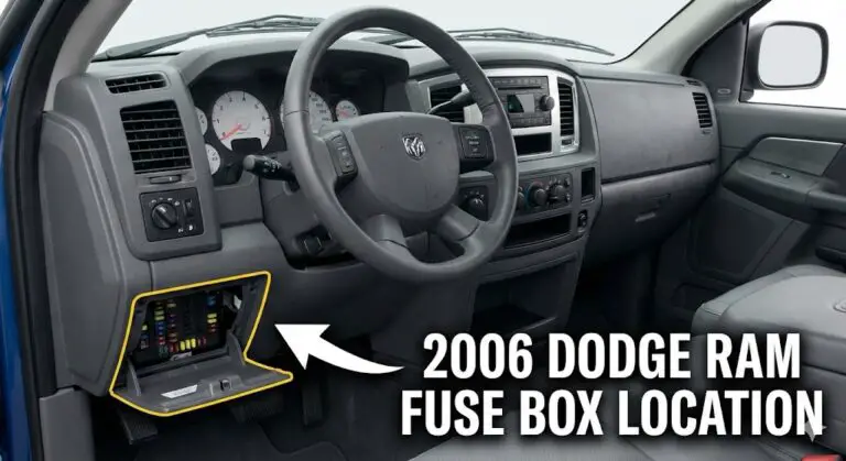
Many owners look for a fuse box inside the cabin near the driver’s side door. There is NO serviceable internal fuse box in the 2014 Ram 1500.
All user-serviceable fuses are located under the hood.Under-Hood Location Map
The TIPM is located in the engine compartment. When facing the truck, it is on the left side (passenger side), near the battery.
Fuse Type Composition
The 2014 Ram 1500 uses a mix of modern micro fuses and heavy-duty cartridge fuses. Knowing which type to buy before heading to the auto parts store is essential.
Top 5 Most Common Fuse Failures
Based on owner search volume and forum reports, these are the fuses most likely to blow. The “Cigar Lighter” and “Power Outlets” are the most frequent culprits due to overloading with phone chargers and accessories.
| Fuse ID | Amps / Color | Circuit Protected |
|---|---|---|
| F90 / F91 | 20A Yellow | Power Outlet (Rear / Front) |
| F93 | 20A Yellow | Cigar Lighter |
| F53 | 20A Yellow | Trailer Tow – Left Stop/Turn |
Amperage Rating Distribution
This radar chart visualizes the distribution of amperage ratings across the fuse box. A high prevalence of 20A and 10A fuses indicates the system handles many medium-load accessories (lights, modules) versus fewer high-load heavy components.
Diagnostic Workflow
Follow this flowchart to safely identify and replace a blown fuse without damaging the sensitive TIPM.
Ignition OFF
Ensure the truck is completely off. Remove the key.
Open TIPM Lid
Release the two side clips. Locate the fuse diagram printed on the underside of the lid.
Visual Inspection
Pull the suspect fuse. Look at the U-shaped wire inside.
⚠ TIPM Fuel Pump Relay Failure
A known issue for the 2011-2014 Ram 1500 is the internal failure of the Fuel Pump Relay, which is soldered directly onto the TIPM circuit board and cannot be simply pulled out and replaced like a fuse. If your fuse (M25) is good but the truck won’t start (or the fuel pump stays on after the engine is off), the internal relay may be bad. This often requires a TIPM bypass cable or a complete board replacement.
The Evolution of Power Distribution
To appreciate the layout of the 2014 Ram's fuse system, one must understand the engineering constraints of the time. In previous decades, manufacturers utilized a distributed fuse system: a Power Distribution Center (PDC) under the hood for high-amperage engine components, and a Junction Block (JB) inside the cabin (usually the kick panel or dashboard side) for interior amenities. This reduced wire length for interior switches.
However, the 2014 Ram 1500 marks a decisive consolidation. To reduce manufacturing complexity, weight, and the number of failure points associated with long harness runs, engineers centralized the vast majority of circuit protection into the engine bay. This shift confuses many owners used to older paradigms, leading to the persistent search for a "missing" interior fuse box. This report will definitively map where every circuit terminates, debunking the myths and highlighting the few true exceptions where inline fuses still exist in the cabin shadows.
Anatomy of the Power Source: The Totally Integrated Power Module (TIPM)
The term "Fuse Box" is a misnomer for the black box sitting next to the battery in a 2014 Ram 1500. While it performs the function of housing fuses, the TIPM is a sophisticated computing device that serves as the gateway for the vehicle's entire electrical grid.
Technical Construction and Logic
The TIPM is a printed circuit board (PCB) housed in a plastic enclosure. It contains:
- Fuses: Sacrificial elements to protect against overcurrent.
- Relays: Electromechanical switches to control high-load circuits.
- Microprocessors: Logic chips that communicate with the ECU (Engine Control Unit), BCM (Body Control Module), and other systems via the CAN (Controller Area Network) bus.
When you activate the windshield wipers, the stalk on the steering column does not send 12 volts to the wiper motor. Instead, it sends a low-voltage digital signal to the Steering Column Control Module (SCCM). The SCCM broadcasts a message over the CAN bus: "Wiper Request: ON." The TIPM reads this message, checks if the conditions are met (e.g., ignition on), and then energizes the internal wiper relay, sending power to the motor.
The Vulnerability of Integration
The "Integrated" part of the TIPM is its Achilles' heel. In a traditional setup, if a relay failed, you pulled it out and plugged in a $10 replacement. In the 2014 Ram TIPM, many key relays—most notably the Fuel Pump Relay—are soldered directly to the internal PCB. They are not user-serviceable. This means a single $5 component failure can necessitate the replacement of a $1,200 module, a reality that has spawned a cottage industry of bypass cables and circuit board repairs.
Environmental Exposure and Degradation
Located in the engine bay, the TIPM is subjected to extreme thermal cycling. From sub-zero winter starts to under-hood temperatures exceeding 200°F during towing, the materials expand and contract. This thermal stress can cause:
- Solder Joint Fatigue: Micro-cracks in the PCB solder joints, leading to intermittent connections.
- Moisture Intrusion: If the lid is not securely fastened, water can enter, bridging circuits and causing the "possessed truck" symptoms where horns honk and wipers flail randomly.
- Corrosion: Proximity to the lead-acid battery subjects the copper contacts to acidic vapors, increasing resistance and heat.
Location and Access: Navigating the Engine Bay
For the 2014 Ram 1500 owner, all roads lead to the engine compartment. Unlike sedans or older trucks, there is no primary fuse panel inside the passenger cabin.
Primary Location: The Power Distribution Center (PDC)
The TIPM is located on the driver’s side (left) of the engine compartment.
- Coordinates: Directly behind the driver-side headlight and immediately forward of the battery. It is often nestled near the brake fluid reservoir.
- Visual Identification: A large, rectangular black box, approximately 6x10 inches.
- Orientation: The long axis typically runs parallel to the fender.
Access Protocols
Accessing the fuses is a tool-free operation, but specific care must be taken to maintain the weather seal.
- Safety Check: Ensure the transmission is in Park, the ignition is OFF, and the key is removed.
- Latch Manipulation: Identify the two plastic retention tabs on the side of the cover facing the engine or the battery (depending on exact sub-model molding).
- Opening: Depress the tabs simultaneously. They are often stiff. Lift the cover straight up.
- Stowage: Do not place the cover on the battery terminals. Place it on the cowl or a workbench.
- Inspection: The underside of the cover contains a diagram (legend). Critical Note: Over ten years, heat often warps this sticker or makes the adhesive fail. The diagrams provided in Section 5 of this report should be considered the primary reference.
The "Internal Fuse Box" Myth
A significant volume of user queries relates to finding the "internal" fuse box. This confusion stems from three sources:
- Legacy Knowledge: Owners of 2nd and 3rd Gen Rams remember the dash panel fuses.
- Competitor Design: Ford and Chevy often maintained interior panels in 2014.
- The "Dash Panel": There is a removable plastic panel on the side of the dashboard (visible when the driver's door is open). Popping this off reveals structural bolts, not fuses.
Fuse Types and Electrical Theory
Before diving into the specific fuse map, it is vital to understand the protection devices used. The 2014 Ram 1500 utilizes a mix of fuse form factors, each designed for a specific load profile.
Micro Fuses (Blade Type)
These are the smallest fuses, typically protecting low-amperage control circuits (5A to 30A).
- Characteristics: Two narrow metal blades, compact plastic body.
- Usage: Airbags, instrument cluster, radio head unit, ignition signals.
- Diagnostics: Difficult to pull with fingers; require the yellow puller tool located in the TIPM or needle-nose pliers.
Cartridge Fuses (J-Case)
These are box-shaped fuses with a clear plastic top, designed for high-current applications (20A to 60A).
- Characteristics: Female terminals (sockets) rather than blades. They plug onto male spades in the fuse box.
- Usage: ABS pump, starter solenoid, trailer power, blower motor.
- Diagnostics: The clear top allows visual inspection of the filament, but they can be stubborn to remove.
Auto-Reset Circuit Breakers
Rarely used in the primary slots but occasionally found for window motors or power seats. These trip when hot and reset when cool, allowing functionality to return without part replacement.
The Physics of Failure
A fuse blows when the current (Amperage) exceeds the rating of the filament. This generates heat ($I^2R$), melting the metal and breaking the circuit.
- Short Circuit: A massive spike in current (e.g., a hot wire touching the frame). The fuse blows instantly and often violently (blackened case).
- Overload: A gradual increase in current (e.g., a seizing fan motor or too many devices on a lighter socket). The fuse melts slowly.
Comprehensive Fuse Matrix: 2014 Ram 1500
This section details every fuse cavity in the 2014 Ram 1500 TIPM. This data is aggregated from multiple service manual sources and visual verifications to ensure accuracy across trim levels (Tradesman, SLT, Laramie, Longhorn).
High-Power Distribution (Cartridge Fuses)
Fuses F01–F39 are primarily Cartridge/J-Case fuses handling major systems.
| Cavity | Amps | Color | Circuit Description & Diagnostic Notes |
| F01 | 80A | Black | Rad Fan Control Module: Primary cooling. If overheating in traffic, check this. |
| F03 | 60A | Yellow | Rad Fan: Secondary power for electric fans. |
| F05 | 40A | Green | Air Suspension Compressor: Critical for models with air ride. If truck sags, check F05. |
| F06 | 40A | Green | ABS / ESC Pump: Anti-lock braking motor. Blown fuse = ABS light ON. |
| F07 | 40A | Green | Starter Solenoid: CRITICAL. If you hear a "click" but no crank, verify this fuse first. |
| F08 | 20A | Blue | Emissions (Diesel): NOx sensors / DEF system (EcoDiesel/Cummins). |
| F09 | 30A | Pink | Diesel Fuel Heater: Prevents gelling in cold weather (Diesel only). |
| F10 | 40A | Green | Body Controller / Exterior Lighting #2: Feeds BCM for headlights/taillights. |
| F11 | 30A | Pink | Integrated Trailer Brake Module (ITBM): Factory trailer brake controller power. |
| F12 | 40A | Green | Body Controller #3 / Interior Lights: Dome lights, cargo lamps. |
| F13 | 40A | Green | Blower Motor: HVAC fan. If A/C blows weak or not at all, check here. |
| F14 | 40A | Green | Body Controller #4 / Power Locks: Central locking system. |
| F16 | 30A | Pink | Smart Bar: Electronic Sway Bar Disconnect (Power Wagon / Off-Road trims). |
| F19 | 20A | Blue | SCR Module: Selective Catalytic Reduction (Diesel emissions). |
| F20 | 30A | Pink | Passenger Door Module: Window/Lock power for passenger side. |
| F21 | 30A | Pink | Drive Train Control Module (DTCM): Transfer case shift motor (4WD). |
| F22 | 20A | Blue | Engine Control Module (ECM): The brain of the engine. |
| F23 | 30A | Pink | Body Controller #1: Feeds various BCM logic circuits. |
| F24 | 30A | Pink | Driver Door Module: Master window switch power. |
| F25 | 30A | Pink | Front Wiper Motor: High/Low speed power. |
| F26 | 30A | Pink | ABS / Stability Control Valves: Solenoids that modulate brake pressure. |
| F28 | 20A | Blue | Trailer Tow Backup Lights: 7-pin connector, center pin. |
| F29 | 20A | Blue | Trailer Tow Parking Lights: 7-pin connector, brown wire circuit. |
| F30 | 30A | Pink | Trailer Tow Receptacle: 12V constant power (battery charge) to trailer. |
| F31 | 30A | Pink | Urea Heater (EcoDiesel): DEF tank heater. |
| F32 | 30A | Pink | DTCM: Secondary transfer case power. |
| F33 | 20A | Blue | Special Services: Police/Fleet upfitter power. |
| F34 | 30A | Pink | VSIM #2: Vehicle System Interface Module (Fleet integration). |
| F35 | 30A | Pink | Sunroof: Motor power. |
| F36 | 30A | Pink | Rear Defroster: Rear glass heating element. |
| F37 | 30A | Pink | Fuel Heater #2: Cummins diesel specific. |
| F38 | 30A | Pink | Power Inverter: 115V AC outlet on dash (150W max). |
| F39 | 30A | Pink | VSIM #1: Fleet interface primary. |
Micro Fuses (Control & Accessories)
Fuses F41–F104 are Micro fuses handling electronics and interior accessories.
| Cavity | Amps | Color | Circuit Description & Diagnostic Notes |
| F41 | 10A | Red | Active Grill Shutter: Aerodynamic flaps behind grille. |
| F42 | 20A | Yellow | Horn: Dual note horn power. |
| F44 | 10A | Red | Diagnostic Port (OBD II): CRITICAL. If scan tool won't power up, replace this. |
| F46 | 10A | Red | TPMS: Tire Pressure Monitoring System module. |
| F49 | 10A | Red | Instrument Cluster (IPC): Gauges and info display. |
| F50 | 20A | Yellow | Air Suspension Module: Logic power (not compressor). |
| F51 | 10A | Red | Ignition Node (WIN/PEM): Keyless entry receiver / Ignition switch. |
| F52 | 5A | Tan | Battery Sensor (IBS): Measures voltage/temp at negative terminal. |
| F53 | 20A | Yellow | Trailer Tow Left Stop/Turn: Isolated circuit for trailer left light. |
| F54 | 20A | Yellow | Adjustable Pedals: Motor to move pedals. |
| F56 | 15A | Blue | Diesel Content: Additional sensors. |
| F57 | 20A | Yellow | Transmission: Solenoid pack power (8-speed/6-speed). |
| F58 | 20A | Yellow | Spare: Often populated with a spare fuse. |
| F59 | 10A | Red | SCR Relay: Diesel emissions control. |
| F60 | 15A | Blue | Underhood Lamp: Light inside engine bay. |
| F61 | 10A | Red | PM Sensor: Particulate Matter sensor (Diesel). |
| F62 | 10A | Red | A/C Clutch: Magnetic clutch on A/C compressor. |
| F63 | 20A | Yellow | Ignition Coils: Power to coil packs (Gas engines). |
| F64 | 25A | Clear | Fuel Injectors: Power to fuel rail injectors. |
| F65 | 10A | Red | Media Hub: USB/SD card inputs in console. |
| F66 | 10A | Red | Sunroof / Rain Sensor: Logic power. |
| F67 | 10A | Red | Bluetooth / Uconnect: Hands-free module / CD player. |
| F69 | 15A | Blue | SCR 12V: Diesel only. |
| F70 | 30A | Green | Fuel Pump Motor: MAJOR FAILURE POINT. See Section 6. |
| F71 | 25A | Clear | Amplifier: Alpine premium sound amp power. |
| F72 | 10A | Red | Voltage Stabilizer: Regulates voltage for sensitive modules. |
| F73 | 20A | Yellow | Fuel Transfer Pump: For models with dual tanks (Chassis Cab). |
| F74 | 20A | Yellow | Brake Vacuum Pump: Electric assist for brakes. |
| F75 | 10A | Red | Coolant Valve: Thermal management actuator. |
| F76 | 10A | Red | ABS / ESC Module: Logic power for brake controller. |
| F77 | 10A | Red | Drivetrain Control: Front axle disconnect (4WD engagement). |
| F78 | 10A | Red | ECM / Power Steering: Electric power steering rack logic. |
| F79 | 15A | Blue | Clearance Lights: Roof cab lights ("marker lights"). |
| F80 | 10A | Red | Garage Door / Compass: Overhead console logic. |
| F81 | 20A | Yellow | Trailer Tow Right Stop/Turn: Isolated circuit for trailer right light. |
| F82 | 10A | Red | SCCM / Cruise Control: Steering Column Control Module. |
| F84 | 15A | Blue | Switch Bank: Dash buttons (Tow/Haul, Heated Seats buttons). |
| F85 | 10A | Red | Airbag Module: Occupant Restraint Controller (ORC). |
| F86 | 10A | Red | Airbag Module: ORC secondary feed. |
| F87 | 10A | Red | Air Suspension / Trailer Tow: Logic feed. |
| F88 | 15A | Blue | Cluster: Secondary IPC feed. |
| F90/91 | 20A | Yellow | Power Outlet (Rear/Console): Selectable (Batt/Ignition). |
| F93 | 20A | Yellow | Cigar Lighter: Main dash outlet. |
| F94 | 10A | Red | Shifter / Transfer Case: Rotary shifter module. |
| F95 | 10A | Red | Rear Camera: Power for backup camera. |
| F96 | 10A | Red | Rear Seat Heater Switch: Control signal. |
| F97 | 25A | Clear | Rear Heated Seats: Heating element power. |
| F98 | 25A | Clear | Front Heated Seats: Heating element power. |
| F99 | 10A | Red | HVAC Module: Climate control head unit. |
| F100 | 10A | Red | Upfitter: Aux switch output logic. |
| F101 | 15A | Blue | Electrochromatic Mirror: Auto-dimming mirror power. |
| F104 | 20A | Yellow | Power Outlets: Console/IP outlet. |
System-Specific Diagnostics and Deep Dives
This section expands on the critical systems that frequently confuse owners, analyzing the electrical theory and troubleshooting paths for each.
6.1 The Fuel Pump Relay Crisis (Circuit F70)
The single most notorious issue with the 2014 Ram 1500 is the failure of the Fuel Pump Relay. This is not a fuse issue, but it is inextricably linked to the fuse box.
The Mechanism of Failure:
In the 2014 TIPM design, the relay that switches power to the fuel pump is soldered directly to the circuit board deep inside the box. It is a micro-relay, significantly smaller than the external grey relays used for the horn or wipers. The fuel pump in a 5.7L Hemi or 3.6L Pentastar draws considerable current (8-12 Amps continuous). Over thousands of duty cycles, the tiny contacts inside this micro-relay arc and pit. Eventually, they either:
- Fail Open: The contacts don't touch. The truck cranks but never starts (no fuel pressure).
- Fail Closed (Welded): The contacts weld together. The fuel pump runs continuously, even with the key removed, draining the battery dead overnight.
Diagnostic Path:
- The "Listen" Test: Turn the key to RUN (do not start). You should hear a 2-second hum from the rear of the truck. Silence indicates a failure (open circuit). Continuous humming after key-off indicates a welded relay.
- Fuse F70 Bypass: If the battery is draining, remove Fuse F70 (30A Green) immediately. This cuts the physical link to the pump, saving the battery.
- The Voltage Check: Use a multimeter on Fuse F70. With the key ON, you should see battery voltage. If you have voltage at the fuse but the pump doesn't run, the wiring to the rear or the pump itself is bad. If you have no voltage at the fuse (and the relay should be on), the internal TIPM relay is dead.
Solutions:
- External Relay Bypass: The standard "recall" fix involves cutting the fuel pump wire exiting the TIPM and wiring in an external, heavy-duty relay triggered by a different ignition source (like the F90/91 fuse slot).
- TIPM Replacement: Expensive and likely to fail again unless the new unit has updated internals.
The Trailer Towing Isolation System (F53, F81, F28, F29)
Ram trucks are workhorses, and the 2014 model features a sophisticated "Isolated Trailer Circuit."
Theory of Operation:
In older trucks, the trailer lights were spliced directly into the truck's taillight wiring. If the trailer had a short circuit (very common in boat trailers submerged in water), it would blow the fuse for the truck's taillights, leaving the towing vehicle invisible at night.
The 2014 Ram 1500 uses the TIPM to separate these worlds. The F53 (Left) and F81 (Right) fuses feed relays that are triggered by the truck's turn signals but draw power from a separate bus.
Troubleshooting Implication:
If you plug in a trailer and the trailer lights don't work, but the truck lights do, you almost certainly have a blown fuse in F53/F81/F28/F29. Do not tear apart the trailer wiring until you check these fuses. This is a safety feature working as designed.
The OBD-II Connectivity Issue (Fuse F44)
A common scenario: A driver goes for an emissions test. The technician plugs into the OBD port under the dash and says, "No communication." The truck fails.
The culprit is almost always Fuse F44 (10A).
- Why it blows: This circuit often shares power with the cargo lamp or map lights (depending on cab config). An aftermarket LED bulb installed incorrectly in the dome light can short this circuit, killing the OBD port.
- Context: Modern state inspections require the OBD computer to be "Ready." If power is cut (fuse blown), the internal emissions monitors reset. You must replace the fuse and then drive the "Drive Cycle" (approx. 50-100 miles of mixed driving) before the truck will pass inspection.
The "Cigar Lighter" Confusion (F90/F91, F93, F104)
The 2014 Ram has multiple power outlets, and their fuse locations confuse many.
- F93: Typically the one on the dashboard.
- F104: Often the one inside the center console tub.
- F90/F91: The rear seat outlet.
- The "Selectable" Feature: Fuse F90/F91 is unique. The plastic fuse holder in the TIPM allows the fuse to be inserted in two different positions (offset left or offset right).
- Position 1: Power is Ignition-Switched (Only on when key is on).
- Position 2: Power is Battery-Fed (Always on).
- User Tip: If you need to charge a phone while the truck is off, check if your fuse is in the "Battery" position. If you want to prevent battery drain from a dashcam, move it to "Ignition".
The Myth of the "Hidden" Fuses: A Forensic Investigation
Despite the centralization of the TIPM, the "Hidden Fuse" theory persists. We will clarify exactly what exists inside the cabin.
The "Passenger Side" Inline Fuses
While there is no box, there can be inline fuses.
- Radio / Uconnect: In some specific trims (often lower trims without the Alpine system), there may be a fuse located on the back of the radio head unit itself or taped to the harness behind the glovebox. This is rare in 2014 but possible.
- Diagnostic: If F67 and F71 in the TIPM are good, but the radio is dead, you must pull the radio bezel (two screws under the rubber mat in the top tray, one behind the 115V outlet) to inspect the harness.
The Fleet / Upfitter Harness
Trucks sold as "Chassis Cabs" or with the "VSIM" module (Fuse F34/F39) often have a bundle of blunt-cut wires under the dash near the steering column or behind the kick panel. Upfitters (ambulance/tow truck builders) use these. They may install their own fuse block here. If you bought a used ex-fleet truck, you might find a "hidden" fuse block here, but it is aftermarket, not factory Ram.
The Brake Controller Line
There is a factory harness for an aftermarket brake controller (if the truck didn't come with the ITBM). This connector is located above the driver's left foot, taped to the main harness. It is fed by Fuse F30. There is no fuse at the connector, but a short here will blow F30 under the hood.
Diagnostic Protocols: How to Troubleshoot Like a Pro
Detailed steps for diagnosing electrical faults in the 2014 Ram 1500 without throwing parts at the problem.
The "Voltage Drop" Test
This is superior to a simple continuity test for checking high-current circuits (like the starter or fuel pump).
Scenario: The starter clicks but turns slowly. Fuse F07 is good.
Procedure:
- Set Multimeter to DC Volts.
- Connect one lead to the positive battery post.
- Connect the other lead to the starter solenoid post (S-terminal).
- Have a helper crank the engine.
- Reading: Ideally, you should see less than 0.5 Volts. If you see 12 Volts (or close to battery voltage) difference while cranking, it means the voltage is being lost in the wire or the TIPM contacts, not reaching the starter.
Parasitic Draw Testing
If your 2014 Ram's battery dies every 3 days, you have a parasitic draw.
Procedure:
- Turn off ignition, close all doors (latch the hood latch with a screwdriver so the truck thinks the hood is closed).
- Wait 30 minutes for all modules (BCM, Radio) to go to "Sleep."
- Disconnect the negative battery cable.
- Connect a Multimeter (set to Amps) in series between the negative post and the negative cable.
- Reading: A healthy Ram 1500 draws 35-50 milliamps (0.035 - 0.050 A).
- Diagnosis: If reading is high (e.g., 2.0 Amps), pull fuses one by one from the TIPM. When the Amps drop, you found the circuit.
- Common Culprit: The Fuel Pump Relay (F70 circuit) stuck on.
- Common Culprit: Aftermarket remote start or alarm.
Visual Inspection of the TIPM
Open the TIPM and look for:
- Green Crust: Copper oxide on fuse legs indicates moisture intrusion.
- Melted Plastic: If a fuse slot is melted but the fuse is intact, the connection was loose, creating an arc (heat) without overcurrent. This requires TIPM repair.
Repair and Maintenance Strategies
Battery Hygiene
The TIPM is extremely sensitive to voltage fluctuations. A dying battery can cause the TIPM to latch "Ghost Codes" or disable outputs.
- Recommendation: Replace the battery every 4 years in hot climates. Clean terminals with baking soda/water solution annually to prevent acidic vapor from corroding the nearby TIPM copper traces.
The "Hard Reset"
Computers glitch. If your radio screen is black or a window won't roll down despite good fuses:
- Disconnect Negative Battery Cable.
- Disconnect Positive Battery Cable.
- Touch the two cable ends together (away from the battery!) for 10 minutes.
- Why: This discharges the capacitors in the BCM and TIPM, forcing a cold reboot of the operating system.
- Reconnect and test.
Bypassing the TIPM (Emergency Field Fix)
If you are stranded with a bad fuel pump relay (Section 6.1):
- Safety: This is for emergency use only.
- Locate: Fuse F91 (Rear Outlet) and Fuse F70 (Fuel Pump).
- The Jumper: Create a fused jumper wire.
- Connect: Insert one end into the load side of F91 (switched power) and the other into the load side of F70 (feed to pump).
- Result: The fuel pump will run when the key is on. Note: This bypasses the safety shutoff in a crash. Fix properly ASAP.
Conclusion and Future Outlook
The 2014 Ram 1500's electrical system is a study in the trade-offs of modern automotive engineering. The Totally Integrated Power Module offers incredible diagnostic power and manufacturing efficiency, but it centralizes failure points in a way that can frustrate the unprepared owner. By understanding that the "Fuse Box" is actually a computer, and by knowing the precise location of the 80+ circuits mapped in this report, owners can demystify the "ghosts" in the machine.
There are no hidden fuse boxes inside the cabin—only the inline remnants of specific accessories. The true battleground is under the hood, next to the battery, where thermal cycles and solder joints determine the reliability of the truck. Whether it is the notorious F70 fuel pump circuit or the isolated trailer lighting, the 2014 Ram 1500 rewards the owner who possesses detailed knowledge and a multimeter.
For detailed guides on mechanical maintenance to complement this electrical knowledge, explore our resources on(https://truckguider.com/ram-1500-towing-capacity/) and Common Engine Issues.
Frequently Asked Questions (FAQ)
Q: Where is the interior fuse box on a 2014 Ram 1500?
A: It does not exist. Unlike previous generations, the 2014 model centralized all fuses into the TIPM under the hood. There is a dash panel that pops off, but it only contains bolts.
Q: My 2014 Ram 1500 cranks but won't start. I checked the F70 fuse and it's good.
A: This is likely the internal TIPM fuel pump relay failure. The fuse is good, but the switch inside the board is bad. Try the "listen test" for the pump hum. You may need an external relay bypass kit.
Q: Which fuse controls the radio?
A: The primary power comes from F67 (10A Red) for the head unit and F71 (25A Clear) for the amplifier. Also check F49 (Instrument Cluster) as they communicate.
Q: Why do my trailer lights not work, but my truck lights are fine?
A: Check fuses F53 (Left) and F81 (Right) in the TIPM. The truck uses separate fuses for the trailer to protect the main system.
Q: Can I replace the fuel pump relay myself?
A: Not easily. It is soldered to the circuit board. You either need to be skilled at soldering and board repair, replace the whole TIPM, or install an external bypass wire.
Q: Where is the fuse for the cigarette lighter?
A: F93 (20A) typically controls the dash outlet, while F104 controls the console, and F90/F91 controls the rear. Note that F90/91 can be moved to change between "Always On" and "Key On."
Q: My OBD port has no power and I can't pass inspection.
A: Replace Fuse F44 (10A Red) in the TIPM. It often blows if the dome light circuit shorts out.
Q: How do I reset the TIPM?
A: Perform a "battery disconnect" reset. Remove both battery cables and touch them together for 10 minutes to drain the capacitors.