Boost Pressure Sensor Location: The Ultimate Guide (Cummins, Powerstroke, Duramax)
In the world of modern diesel trucks, the relentless pursuit of power, torque, and efficiency hinges on a complex symphony of electronic sensors and mechanical components. At the heart of this system, particularly in turbocharged engines, lies a small but indispensable device: the boost pressure sensor. Often referred to as a Manifold Absolute Pressure (MAP) sensor, this component is the primary source of information for the Engine Control Module (ECM) regarding the air pressure being forced into your engine. Its precise location and flawless operation are non-negotiable for achieving the performance and reliability you expect from your truck.
This comprehensive guide serves as the definitive resource for locating the boost pressure sensor in the most popular diesel truck engines, including Cummins, Powerstroke, and Duramax platforms. Beyond simple location diagrams, this report delves into the sensor’s critical function, the common confusion surrounding its terminology, the tell-tale symptoms of failure, and a detailed breakdown of the diagnostic trouble codes (DTCs) it can trigger. Whether you are a seasoned technician, a fleet manager, or a DIY truck owner, this information will empower you to diagnose, locate, and address issues related to this vital component.
The Trucker’s Guide to the Boost Pressure Sensor
A visual breakdown of what it is, where to find it, and why it matters.
What is a Boost Pressure Sensor?
Often called a Manifold Absolute Pressure (MAP) sensor in turbocharged engines, this small device is critical for performance. It measures the air pressure inside the intake manifold—the “boost” generated by your turbocharger. This data is sent directly to the Engine Control Unit (ECU), which then calculates the precise amount of fuel to inject for the perfect air-fuel mixture.
A failing sensor can lead to a severe drop in engine power and efficiency.
Why It’s Critical: The Data Flow
The sensor is the ECU’s “eyes” on the turbo. This simple flow shows its vital role in your engine’s operation. When this data is wrong, the entire system suffers.
Signs of a Failing Sensor
A bad boost sensor can mimic other serious engine problems. The most common complaint is a significant loss of power, as the ECU defaults to a “safe” (low-boost, rich-fuel) mode to protect the engine. This chart shows a typical breakdown of symptoms reported by drivers.
- Reduced Engine Power: The engine feels sluggish and won’t accelerate properly.
- Check Engine Light: Often logs fault codes related to “MAP Sensor Circuit High/Low.”
- Poor Fuel Economy: The engine runs rich, wasting fuel.
- Black Smoke: A classic sign of too much fuel and not enough air (running rich).
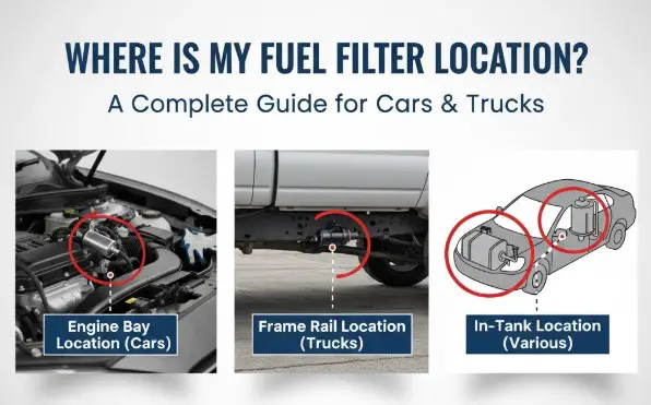
The Core Question: Where is it Located?
Finding the sensor is the first step. Its location varies by engine design, but it’s always somewhere along the “boosted” air path *after* the turbo and *before* the engine’s cylinders. Here are the three most common locations.
Location by Popular Truck Engine
While the diagram shows general spots, specific engines have their go-to locations. Here’s a quick reference for the “Big 3” diesel truck engines.
| Engine | Common Location |
|---|---|
| Cummins (e.g., 6.7L) | On the intake manifold, top of the engine, driver’s side. Often has two sensors (one for boost, one for ambient). |
| Ford Power Stroke (e.g., 6.7L) | Typically on the charge pipe leading from the intercooler to the intake, near the top of the engine. |
| GM Duramax (e.g., L5P) | On the intake manifold, easily accessible at the front-top of the engine. |
By the Numbers: Repair Costs
The sensor itself is relatively inexpensive, but shop labor rates can add up. This chart shows the typical cost difference between a DIY repair and taking it to a mechanic.
Simple Diagnostic Flow
If you suspect a bad sensor, follow these basic steps. Always consult a proper repair manual for your specific vehicle before starting any work.
The Core Function: Why Your Truck’s Boost Pressure Sensor is Non-Negotiable
To understand why finding and maintaining the boost pressure sensor is so critical, one must first appreciate its role within a forced induction system. Turbochargers and superchargers are essentially sophisticated air pumps; they compress ambient air and force it into the engine’s combustion chambers.1 More air allows for more fuel to be burned, which translates directly into more power. However, this process must be meticulously controlled. Unregulated boost pressure can lead to catastrophic engine failure.
The boost pressure sensor acts as the “eyes and ears” of the ECM, providing a real-time data stream of the pressure within the intake manifold. This single data point is a cornerstone for three pillars of engine management:
- Precise Fuel Metering: The ECM combines the boost pressure reading with data from the Intake Air Temperature (IAT) sensor to calculate the density and mass of the air entering the engine. With this information, it can inject the exact amount of fuel required to achieve the optimal air-fuel ratio for complete combustion, maximizing power and efficiency.
- Optimized Ignition Timing: The pressure data allows the ECM to dynamically adjust ignition timing. Under high boost, it can retard timing to prevent engine knock (detonation), a highly destructive phenomenon that can damage pistons and cylinder heads.
- Turbocharger Wastegate Control: Perhaps its most critical role is as a safeguard. The sensor’s readings tell the ECM when the desired boost level has been reached. The ECM then actuates the turbocharger’s wastegate to divert excess exhaust gas away from the turbine wheel, preventing the turbo from spinning faster and creating an over-boost condition that could severely damage the engine.
The sensor’s function is therefore a duality of performance and protection. It enables the engine to generate immense power by providing the data needed for aggressive fueling and timing, but it also defines the safe operating limits. A failing sensor doesn’t just result in a loss of power; it can leave the engine vulnerable by removing the very feedback loop designed to protect it from self-destruction. This dual role underscores its non-negotiable importance in any modern turbocharged truck.
MAP vs. Boost Sensor: Decoding the Most Common Point of Confusion
One of the most significant sources of confusion for technicians and DIYers is the terminology surrounding pressure sensors in the intake tract. The terms “Boost Pressure Sensor” and “Manifold Absolute Pressure (MAP) Sensor” are often used interchangeably, yet they measure pressure in fundamentally different ways. Understanding this distinction is crucial for accurate diagnosis.
- Manifold Absolute Pressure (MAP) Sensor: This sensor measures absolute pressure. Its reading is relative to a perfect vacuum (zero pressure). A MAP sensor will never display a negative value because a perfect vacuum is its zero point.
- Boost Pressure Sensor/Gauge: This sensor, or the gauge on your dashboard, measures gauge pressure. Its reading is relative to the current atmospheric pressure. It measures the pressure above the ambient air pressure.
The relationship between these two measurements can be expressed with a simple formula:
$$MAP_{\text{absolute}} = P_{\text{atmospheric}} + P_{\text{boost gauge}}$$
For example, at sea level, atmospheric pressure is approximately 14.7 PSI. When your truck is off, a boost gauge will read 0 PSI, but a scan tool reading the MAP sensor will show approximately 14.7 PSI (or about 100 kPa). If your turbo is producing 20 PSI of boost, your gauge will read 20 PSI, but the MAP sensor is actually reading 34.7 PSI ($14.7 + 20$).
The confusion exists because modern trucks typically use a single, robust MAP sensor to perform both functions. The physical component screwed into the intake manifold is an absolute pressure sensor. The ECM reads this absolute pressure and simultaneously reads the atmospheric pressure from a separate barometric pressure (BARO) sensor (or it takes a BARO reading from the MAP sensor before the engine starts). It then calculates the gauge pressure (“boost”) for the dashboard display by subtracting the atmospheric pressure from the MAP reading.
This is why the component is often called a MAP sensor in service manuals and parts catalogs, even though its primary job in a turbocharged application is to measure boost. The distinction is not merely academic; it is critical for diagnostics. A technician using a scan tool will see absolute pressure values, while the driver reports issues based on the gauge pressure they see on the dash. Understanding how to convert between the two is essential for determining if the sensor’s readings are logical.
MAP vs. Boost Sensor – Key Differences
| Feature | MAP Sensor | Boost Sensor / Gauge |
| Measures | Absolute Pressure (relative to vacuum) | Gauge Pressure (relative to atmosphere) |
| Reading at Sea Level (Engine Off) | ~$14.7$ PSI (~$100$ kPa) | $0$ PSI |
| Reading at Idle (Vacuum) | < $14.7$ PSI (e.g., $5$ PSI) | Negative PSI (e.g., $-10$ PSI or inHg) |
| Reading Under Boost (15 PSI) | ~$29.7$ PSI | $15$ PSI |
| Primary ECU Use | Calculates air density and mass for fuel/timing | Often a calculated value for driver display |
Common Locations: Where to Start Your Search for the Boost Pressure Sensor
Before diving into engine-specific guides, it is helpful to understand the general principles governing the sensor’s placement. To do its job, the sensor must be positioned in the intake air stream after the turbocharger’s compressor has pressurized the air but before that air enters the engine’s cylinders. This logic dictates three primary locations where you are most likely to find it.
- On the Intake Manifold: This is a very common placement. Mounting the sensor directly on the intake manifold provides the ECM with the most accurate reading of the pressure just before it is drawn into the combustion chambers.
- On the Intercooler or Charge Piping: The sensor can also be found mounted on the pipes that carry compressed air from the turbo to the intercooler and from the intercooler to the intake manifold. Some advanced systems, like on the tenth-generation Honda Civic, use two sensors—one before and one after the intercooler—to allow the ECM to measure pressure drop across the intercooler and fine-tune performance.
- On the Turbocharger Housing: While less common, some designs integrate the boost sensor directly into the compressor housing of the turbocharger itself.
By tracing the path of the charge air piping from the turbocharger outlet towards the engine’s intake, you will inevitably encounter the boost pressure sensor in one of these three zones.
Engine-Specific Location Guides: Find Your Sensor Now
While the general principles apply to all trucks, each manufacturer and engine generation has its own specific placement for the boost pressure sensor. The following sections provide detailed location information for the most prevalent diesel truck engines on the road.
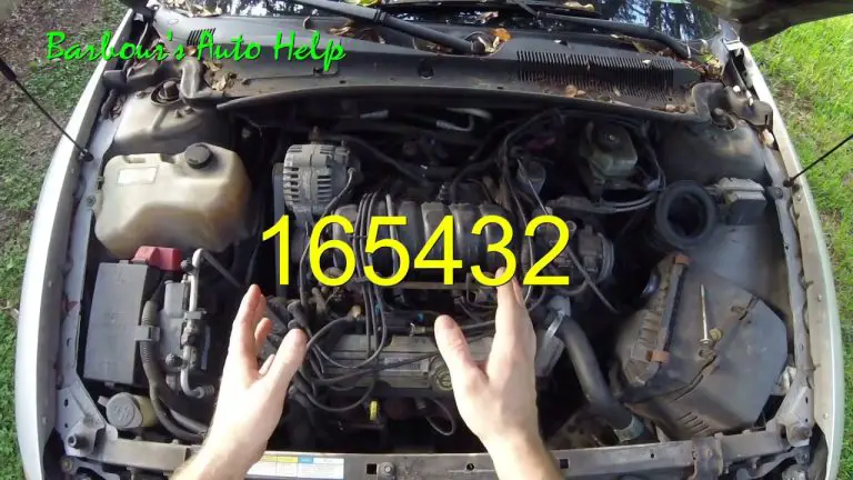
Cummins Boost Pressure Sensor Location
Cummins engines, particularly the legendary 5.9L and 6.7L, are known for their straightforward design, and the boost sensor placement is generally consistent.
5.9L Cummins (Common Rail, 2003-2007):
The sensor, most often referred to as the MAP sensor in Cummins literature, is located on the driver’s side of the engine, screwed into the intake manifold.14
- Typical Location: Look on top of the intake manifold, towards the rear of the engine, near the firewall. It sits in a relatively tight area, nestled among fuel lines and other components.
- Visual Cues: It is a small, typically black plastic sensor with a three-wire electrical connector, held in place by two small bolts (often 10mm or Torx head).
- Pro-Tips for Removal/Installation: Due to the tight quarters, access can be challenging. Once the bolts are removed, the sensor may be snug in its bore. It is often necessary to gently rock it back and forth to break the O-ring seal.14 When installing a new sensor, applying a thin coat of dielectric grease or clean engine oil to the new O-ring is highly recommended. This lubricates the seal, preventing it from tearing or rolling during installation, which would cause a boost leak.
Powerstroke Boost Pressure Sensor Location
Ford’s Powerstroke engine family has seen significant evolution, and the boost sensor location has changed accordingly.
7.3L Powerstroke (1999-2003):
On the venerable 7.3L, the MAP sensor is not directly mounted to the manifold.
- Typical Location: It is found mounted on the firewall or on a bracket on top of the engine’s passenger side, near the A/C evaporator case.
- Visual Cues: Look for a small rectangular sensor with an electrical connector and a rubber hose attached to a nipple on its side. This hose runs from the sensor to a port on the intake manifold, supplying the pressure reading.
6.0L Powerstroke (2003-2007):
The 6.0L follows a similar design to the 7.3L, using a remotely mounted sensor connected by a hose. This design is a known trouble spot.
- Typical Location: The sensor itself is typically mounted on the passenger side of the upper intake manifold. It is crucial to distinguish it from the nearby Exhaust Back Pressure (EBP) sensor, which looks similar but measures exhaust pressure.
- Common Failure Point: The rubber hose connecting the sensor to the intake manifold nipple is prone to becoming brittle, cracked, or clogged with oil and carbon residue. The nipple on the intake manifold can also become completely blocked. This often leads to a P0299 underboost code, not because the turbo is failing, but because the sensor cannot get an accurate pressure reading.
6.7L Powerstroke (2011-Present):
The 6.7L Powerstroke features a more modern design with the sensor mounted directly to the intake.
- Typical Location: The MAP sensor is located directly on top of the plastic upper intake manifold, slightly to the passenger side of the centerline.
- Visual Cues: It is easily accessible after removing the engine cover and is held in place by a single small bolt (often 7mm or 8mm).
- Critical Maintenance Insight: The 6.7L Powerstroke’s EGR (Exhaust Gas Recirculation) system introduces soot directly into the intake manifold. This soot heavily contaminates the MAP sensor, caking the sensing element in a thick layer of carbon. This buildup can insulate the sensor, causing it to read pressure inaccurately or respond slowly to changes. This can lead to a fluctuating boost gauge, hesitation, and poor performance, often without triggering a check engine light. For 6.7L owners, the preventative removal and cleaning of this sensor with a dedicated electronics cleaner should be considered a routine maintenance item. A fluctuating boost gauge on these trucks should lead to an inspection of this sensor first, before suspecting a more serious turbocharger issue.
Duramax Boost Pressure Sensor Location
The GM Duramax engine line has perhaps the most variation in sensor location, and diagnosis requires understanding a more complex system of related components.
LB7 (2001-2004):
- Typical Location: The MAP sensor is located on top of the engine, under the large plastic air intake resonator cover. It is typically mounted in the neck of the cast aluminum “Y-bridge” that feeds air into both cylinder heads.21 On early 2001 models, it may be located in one of the intake runners instead.
LLY (2004.5-2005):
- Typical Location: The LLY is notorious for having the most difficult-to-access MAP sensor. It is located on the driver’s side of the engine, mounted low and behind the A/C compressor. Access often requires removing the driver’s side inner fender liner and working in a very confined space.
LBZ / LMM (2006-2010):
- Typical Location: GM improved accessibility on these models. The MAP sensor is typically located on the driver’s side of the intake tract, near the throttle body assembly, making it much easier to service than the LLY.
LML (2011-2016):
- Typical Location: The LML features a more complex system. A dedicated Turbocharger Boost Pressure Sensor is often located directly in the compressor cover of the turbocharger itself. Additionally, a separate Manifold Absolute Pressure (MAP) Sensor is located on the intake manifold to provide a final pressure reading before the air enters the cylinders.
It is vital for Duramax owners to recognize that a perceived “boost problem” may not stem from the boost pressure sensor itself. These engines heavily rely on a Turbo Vane Position Sensor to communicate the position of the variable geometry turbo’s (VGT) vanes to the ECM.
A failure of this sensor can prevent the turbo from building boost correctly, leading to symptoms that mimic a bad boost pressure sensor. Proper diagnosis on a Duramax requires a holistic approach that considers the entire ecosystem of turbo-related sensors, not just the MAP sensor. Misdiagnosis can easily lead to replacing the wrong, and often expensive, component.
Symptoms of a Failing Boost Pressure Sensor
When a boost pressure sensor begins to fail, it sends inaccurate or irrational data to the ECM. The ECM, in turn, makes incorrect decisions about fuel, timing, and boost control, leading to a cascade of noticeable symptoms. If your truck is exhibiting several of the following signs, a faulty boost pressure sensor is a strong possibility.
Performance Degradation:
- Lack of Power & Sluggish Performance: This is the most common symptom. If the sensor is reading lower than actual boost, the ECM will not command enough fuel, causing the engine to feel weak and unresponsive.
- Poor Acceleration & Hesitation: The truck may stumble or hesitate under acceleration as the ECM struggles to match fuel delivery to the incorrect air pressure readings.
- Excessive Turbo Lag: The delay before the turbocharger builds boost may feel significantly longer than usual, as the entire management system is out of sync.
- Increased Fuel Consumption: An inaccurate sensor can cause the ECM to command a rich fuel mixture (too much fuel for the air available), drastically reducing fuel economy.
Engine & Exhaust Issues:
- Check Engine Light (CEL) Illuminated: A sensor that has failed electrically or is providing readings far outside the expected range will almost always trigger a CEL and store a diagnostic trouble code.
- Rough or Fluctuating Idle: Inaccurate pressure readings at idle can cause the engine to hunt for a stable speed.
- Black Smoke from Exhaust: A sensor reading high when boost is low can cause a severe over-fueling condition, resulting in plumes of black, unburnt diesel fuel from the exhaust.
- Failed Emissions Test: The poor combustion efficiency caused by a bad sensor will lead to a dramatic increase in harmful emissions.
Audible Warnings & Critical Failures:
- Strange Noises from Turbo: If the sensor fails in a way that causes an over-boost condition, you may hear hissing or whining from the turbocharger as it is forced to work beyond its designed limits.
- Engine Enters “Limp Mode”: This is a self-preservation strategy by the ECM. If it receives data from the sensor that is completely irrational or indicates a dangerous over-boost situation, it will drastically cut engine power to prevent catastrophic damage. The truck will feel extremely sluggish and may not accelerate past a certain speed.
The Mechanic’s Guide: Troubleshooting & Common DTCs
Diagnosing a faulty boost pressure sensor involves a combination of visual inspection, electrical testing, and interpreting the diagnostic trouble codes stored in the ECM. Simply replacing the sensor based on a symptom is not advisable, as other issues like boost leaks or wiring problems can mimic sensor failure.
DIY Diagnostic Steps
- Visual Inspection: Begin with a thorough visual check. Look for any physical damage to the sensor body or connector. Ensure the connector is securely plugged in and free of corrosion, moisture, or dirt. Critically, inspect any associated vacuum or pressure hoses for cracks, collapses, kinks, or blockages, as this is a very common failure point, especially on older Powerstroke models.
- Electrical Testing (with a Multimeter): For a more definitive test, a digital multimeter can be used to verify the sensor’s electrical integrity. The process generally follows these steps:
- Verify Reference Voltage: Disconnect the sensor’s electrical connector. Turn the ignition to the “Key On, Engine Off” position. Set your multimeter to DC volts. Probe the reference voltage pin on the harness-side connector (typically Pin C or 3) and a good chassis ground. You should see a steady voltage of approximately 5.0V. If not, there is a problem with the wiring or the ECM itself.
- Check Ground: Probe the ground pin on the harness-side connector (typically Pin A or 1) and the negative battery terminal. The multimeter, set to continuity or ohms, should show a near-zero reading, indicating a good ground path.
- Test Signal Voltage: Reconnect the sensor. With the engine idling, carefully back-probe the signal wire (typically the middle pin, B or 2). At idle (in a vacuum condition), the voltage should be low, generally between 0.25V and 1.8V. As engine RPM increases and boost builds, this voltage should climb smoothly and proportionally, reaching up to 4.7V under full boost. A signal that is stuck, erratic, or does not change with engine load indicates a faulty sensor.
Decoding the DTCs
When the ECM detects a problem with the boost pressure sensor or its circuit, it will store a specific DTC. Understanding these codes is the key to a fast and accurate diagnosis. It is important to differentiate between “Circuit” codes and “Performance” codes. A circuit code points directly to an electrical fault (the sensor, the wiring, or the ECM), making diagnosis more straightforward. A performance code is more ambiguous, indicating that the sensor’s reading is illogical in the context of other sensor data, which could be a bad sensor or a mechanical problem like a massive boost leak or a stuck wastegate.
Common Boost Sensor Diagnostic Trouble Codes (DTCs)
| DTC | Code Definition | Common Causes | What It Means for Your Truck |
| P0236 | Turbo/Supercharger Boost Sensor “A” Circuit Range/Performance | Faulty sensor, vacuum/boost leak, wiring issue, stuck wastegate, clogged air filter. | The ECM is seeing a pressure reading that doesn’t make sense for the current engine speed and load. It’s an irrational signal, not necessarily an electrical fault. |
| P0237 | Turbo/Supercharger Boost Sensor “A” Circuit Low | Faulty sensor, short to ground in signal wire, open in reference circuit, bad ECM. | The signal voltage from the sensor is below the minimum expected threshold. This is a clear electrical fault code. |
| P0238 | Turbo/Supercharger Boost Sensor “A” Circuit High | Faulty sensor, short to voltage in signal wire, bad ground connection. | The signal voltage from the sensor is above the maximum expected threshold (e.g., greater than 4.0V for 5+ seconds). This is also a clear electrical fault code. |
| P0239 | Turbo/Supercharger Boost Sensor “B” Circuit Malfunction | Faulty “B” sensor, wiring issue, clogged sensor port, ECM fault. | In systems with two boost sensors, this code indicates a malfunction in the “B” sensor circuit or a mismatch between the “A” and “B” sensor readings. |
Frequently Asked Questions (FAQs)
Can you clean a boost pressure sensor?
Yes, in many cases, cleaning the sensor can restore its function, particularly if the issue is contamination from oil or carbon buildup, which is common on engines like the 6.7L Powerstroke. Use a dedicated Mass Airflow (MAF) sensor cleaner or electronics cleaner that leaves no residue. Spray the sensing element generously but never touch it with a brush, tool, or your fingers, as it is extremely delicate. If the sensor has failed internally due to an electrical fault, cleaning will not resolve the issue.
What is the difference between a boost sensor and a MAP sensor?
A MAP sensor measures absolute pressure (total pressure relative to a perfect vacuum), while a boost sensor or gauge measures gauge pressure (pressure above the current atmospheric pressure). In most modern trucks, a single physical component—a MAP sensor—is used by the engine’s computer to measure absolute pressure, and the “boost” value is then calculated from that reading for the dashboard display.
How much does it cost to replace a boost pressure sensor?
The cost can vary significantly. The part itself typically ranges from $50 to $150 for a quality OEM or reputable aftermarket sensor. Labor costs depend on the sensor’s accessibility. For an easily reached sensor (like on a 6.7L Powerstroke), expect 0.5 to 1 hour of labor. For a notoriously difficult-to-reach sensor (like on a Duramax LLY), labor could be 1.5 hours or more.
Can a bad boost sensor cause limp mode?
Absolutely. Limp mode is a protective state the ECM initiates to prevent engine damage. If the boost sensor sends a signal that is irrational or indicates a severe over-boost condition, the ECM will cut engine power and fuel delivery to protect the engine and turbocharger, resulting in limp mode.
Will a bad boost sensor always trigger a check engine light?
Not always. A sensor can become sluggish or slightly inaccurate, causing noticeable performance problems like poor fuel economy or hesitation without its signal deviating far enough from the expected range to trigger a specific DTC. The carbon fouling issue on 6.7L Powerstrokes is a prime example where performance can suffer long before a light appears.
6. What is a “bar” of boost?
“Bar” is a metric unit of pressure commonly used in performance tuning circles. One bar is approximately equal to atmospheric pressure at sea level (14.5 PSI). A “4 Bar” MAP sensor, for example, is capable of reading up to 4 times atmospheric pressure. This means it can measure 1 bar of atmospheric pressure plus up to 3 bars of boost pressure (approximately 43.5 PSI of boost)