Where is the Intake Air Temp Sensor Location? A Complete Guide (With Diagrams & Codes)
The Unsung Hero of Your Engine: What is an Intake Air Temperature (IAT) Sensor?
Deep within the complex ecosystem of a modern truck engine, a host of sensors work in concert, feeding a constant stream of data to the central computer. While some components are well-known, others, like the Intake Air Temperature (IAT) sensor, operate quietly in the background. Despite its unassuming size, the IAT sensor is a critical component in the engine management system, providing information that directly impacts power, fuel efficiency, and emissions.1 This sensor is also referred to by other names depending on the manufacturer and its specific location, such as the Air Charge Temperature (ACT) or Manifold Air Temperature (MAT) sensor.2
Its primary function is straightforward: to accurately measure the temperature of the air that the engine is breathing in through its intake system.3 This simple measurement is one of the most fundamental variables the engine’s computer needs to perform its job correctly.
The Critical Link to the ECU: Why Temperature Matters
The importance of the IAT sensor is rooted in basic physics. The density of air—the number of oxygen molecules packed into a given volume—changes significantly with its temperature. Cold air is dense and rich with oxygen, while hot air is less dense and contains less oxygen.2 For an engine to achieve optimal combustion, it must maintain a precise air-to-fuel ratio. The Engine Control Unit (ECU), also known as the Powertrain Control Module (PCM), relies heavily on the IAT sensor’s data to calculate this air density.6
This calculation is a cornerstone of modern engine management, allowing the ECU to make continuous, millisecond-by-millisecond adjustments to several key parameters:
- Optimizing the Air-Fuel Ratio: Based on the calculated air density, the ECU precisely adjusts the amount of fuel delivered by the injectors. If the air is cold and dense, it injects more fuel; if the air is hot and less dense, it injects less fuel. This ensures the engine receives the correct mixture for complete and efficient combustion under all weather conditions.5
- Adjusting Ignition Timing: Air temperature also affects combustion speed and the potential for engine knock, or detonation. The ECU uses the IAT data to fine-tune ignition timing, advancing it for more power when conditions are safe and retarding it to prevent damaging knock when intake temperatures get too high.1
- Controlling Emissions: The precise control over the air-fuel mixture enabled by the IAT sensor is absolutely essential for the effective operation of a vehicle’s emissions control systems. A correct mixture ensures the catalytic converter can work efficiently, and in some vehicles, the data is also used to help regulate the Exhaust Gas Recirculation (EGR) valve, further reducing harmful NOx emissions.5
How it Works: The NTC Thermistor
The IAT sensor is a simple yet elegant piece of technology known as a Negative Temperature Coefficient (NTC) thermistor.5 The name describes its function perfectly: it is a special type of resistor whose electrical resistance has an inverse relationship with temperature. As the air temperature rises, the sensor’s internal resistance decreases, and as the air temperature falls, its resistance increases.8
The ECU leverages this property through a simple electrical circuit. It supplies a regulated 5-volt reference signal to the IAT sensor. This voltage passes through the thermistor and then returns to the ECU. As the sensor’s resistance changes with the air temperature, it alters the voltage signal that the ECU receives back. The ECU is programmed to interpret this change in voltage as a specific temperature reading. A high return voltage, caused by high resistance, signals cold air. Conversely, a low return voltage, caused by low resistance, signals hot air.6
The IAT Sensor’s Evolving Authority
The role and criticality of the IAT sensor have undergone a significant evolution in vehicle design. In early electronic fuel injection (EFI) systems, the IAT was often considered a “low authority sensor.” Its input was used for minor fuel trim adjustments, and a failure might only result in a slight decrease in fuel economy without causing major driveability issues.12
However, in today’s trucks, which are governed by stringent OBD-II regulations and complex emissions controls, the IAT sensor has become a high-authority input. The demand for razor-sharp precision in fuel and ignition control has elevated its importance. This shift is evident in how modern ECUs react to a sensor failure. While an older vehicle might simply illuminate the check engine light, a newer truck may enter a “Limp Home Mode” to protect the engine and catalytic converter from damage caused by an incorrect air-fuel mixture.5 This progression underscores why a fault code related to this seemingly minor sensor should be addressed promptly by any modern vehicle owner.
Demystifying the Intake Air Temp Sensor
A visual guide to what it does, where to find it, and why it matters.
Its Critical Impact on Fuel Economy
The Intake Air Temperature (IAT) sensor is a small but vital component. By telling the engine’s computer (ECU) how dense the incoming air is, it directly influences the air-fuel mixture. A faulty sensor can skew this calculation, potentially reducing fuel economy by a significant margin.
Common IAT Sensor Locations
Finding the IAT sensor is the first step in diagnosis. Its location varies by manufacturer, but it’s almost always found in one of these three primary locations, with integration into the Mass Air Flow (MAF) sensor housing being the most common today.
How the IAT Sensor Informs the ECU
The IAT sensor is a key part of a data feedback loop. It measures the temperature of the air, which the ECU uses to calculate air density. Colder air is denser and requires more fuel; hotter air is less dense and requires less. This entire process happens in milliseconds.
(Measures Temp)
(Calculates Density)
(Adjusts Fuel)
The Sensor’s Signal: Temp vs. Resistance
The IAT sensor is a thermistor, meaning its electrical resistance changes with temperature. As the air gets warmer, the sensor’s internal resistance drops. The ECU reads this change in resistance as a voltage signal to determine the air temperature.
Symptoms of a Failing IAT Sensor
When the sensor fails, it typically sends incorrect data (e.g., telling the ECU it’s -30°C when it’s 80°F). This leads to a rich fuel mixture, causing a cascade of noticeable problems, most commonly a Check Engine Light.
Related Engine Management Systems
The IAT sensor doesn’t work in isolation. It’s part of a complex system of sensors that the ECU relies on to keep the engine running efficiently. Problems with these related components can sometimes mimic a bad IAT sensor.
- Mass Air Flow (MAF) Sensor: Often housed with the IAT, it measures the total *volume* and *mass* of air entering the engine.
- Manifold Absolute Pressure (MAP) Sensor: Measures engine load by reading the pressure (or vacuum) inside the intake manifold.
- Engine Control Unit (ECU): The ‘brain’ of the vehicle that takes data from all sensors (IAT, MAF, MAP, O2, etc.) to control fuel injection and ignition timing.
Understanding this full system is key, as a symptom of a bad MAP sensor
can sometimes be confused with an IAT issue, or both could contribute to why a car jerks when accelerating.Pinpointing the IAT Sensor: The 4 Most Common Locations
The primary challenge for many DIY mechanics is simply finding the IAT sensor. Its location varies significantly between different makes, models, and engine types. However, nearly all configurations fall into one of four common placements.
Location 1: The Standalone Sensor in the Intake Duct
This is one of the most traditional and easily identifiable setups. The IAT sensor exists as a separate, standalone component. It is typically a small plastic or brass probe that is either pushed into a rubber grommet or threaded into the main intake air tube. This tube is the large-diameter flexible hose that connects the air filter box to the engine’s throttle body.5 To spot it, look for a small, two-wire electrical connector plugged into the only sensor located on this section of the intake path.
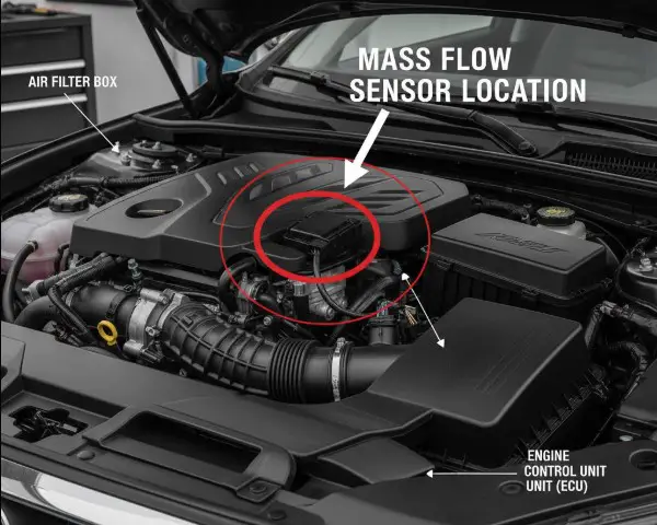
Location 2: Integrated into the Mass Air Flow (MAF) Sensor
To streamline components and reduce wiring, many manufacturers integrate the IAT sensor directly into the Mass Air Flow (MAF) sensor assembly.5 The MAF sensor itself is a larger component located in the intake tract, almost always immediately after the air filter housing.
The definitive way to identify this integrated setup is by counting the wires on the MAF sensor’s electrical connector. A basic MAF sensor only requires three wires to measure air mass. If the connector has four, five, or more wires, it is a clear indication that the assembly also houses the IAT sensor. The additional wires are dedicated to the IAT’s thermistor circuit.5
Location 3: Combined with the Manifold Absolute Pressure (MAP) Sensor
In another common integration, the IAT sensor is combined with the Manifold Absolute Pressure (MAP) sensor. This combination unit is often referred to as a T-MAP sensor (Temperature-Manifold Absolute Pressure) and is typically mounted directly onto the engine’s intake manifold, downstream from the throttle body.5
Similar to the MAF sensor, the giveaway is the pin count on the electrical connector. A standard MAP sensor functions with only three pins. A T-MAP sensor, which includes the IAT function, will have a fourth pin. This extra pin is used to complete the IAT sensor’s circuit, allowing it to send its temperature signal back to the ECU.5
Location 4: Mounted Directly on the Intake Manifold (MAT Sensor)
In some engine designs, particularly older or high-performance applications, a standalone IAT sensor is threaded directly into the body of the intake manifold plenum.5 In this position, it is often specifically called a Manifold Air Temperature (MAT) sensor, as it measures the temperature of the air charge just before it enters the combustion chambers. It will appear as a separate, threaded sensor on the manifold, distinct from the MAP or T-MAP sensor.
The “Heat Soak” Dilemma and Charge Temperature Estimation
The physical placement of the IAT sensor is a carefully considered engineering compromise. On one hand, placing the sensor as close to the cylinders as possible—for example, directly in the intake manifold—provides a more accurate reading of the air temperature just before combustion. On the other hand, this location is highly susceptible to a phenomenon known as “heat soak.” This occurs when the sensor, especially at low engine speeds or after the engine is shut off and restarted while hot, absorbs radiant heat from the hot metal of the intake manifold. This can cause the sensor to report a temperature that is artificially high and not representative of the actual air flowing past it.17
This dilemma is a frequent topic of discussion in performance tuning communities, where accuracy is paramount. An incorrect, heat-soaked reading can cause the ECU to pull ignition timing and alter fuel mixtures unnecessarily, hurting performance. To overcome this physical limitation, sophisticated modern ECUs employ a software strategy called Charge Temperature Estimation.18
Instead of relying solely on the IAT sensor’s reading, the ECU creates a more accurate, calculated “charge temperature.” It does this by intelligently blending the data from the IAT sensor with data from the Engine Coolant Temperature (ECT) sensor, factoring in variables like engine load and airflow. The logic works as follows:
- At low airflow (e.g., idling in traffic), the air moves slowly through the intake and has more time to be heated by the engine. In this scenario, the engine’s own heat (measured by the ECT) has a greater influence on the final charge temperature. The ECU’s algorithm gives more weight to the ECT reading.
- At high airflow (e.g., cruising on the highway), the large volume of fast-moving air is not in the engine bay long enough to be significantly heated. In this case, the IAT sensor’s reading is a more accurate representation of the charge temperature, and the ECU’s algorithm gives it more weight.
This complex modeling demonstrates that the ECU is not just passively reading a sensor; it is actively calculating the most likely temperature of the air entering the cylinders. This advanced logic is crucial for maintaining optimal performance and efficiency across all driving conditions and highlights the intricate relationship between hardware placement and software calibration. For more on performance tuning, consult resources like HP Academy.
Identifying Your IAT Sensor Setup
To simplify identification, a visual representation of an engine’s air intake system can be invaluable.
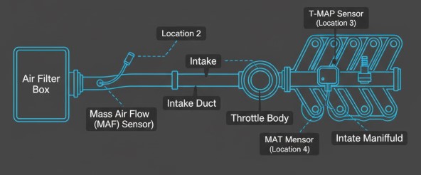
A simple line diagram should be created to illustrate a typical engine air intake path. The drawing would begin with the Air Filter Box on the far left. A line would then lead to a block labeled “Mass Air Flow (MAF) Sensor,” with a callout pointing to it as Location 2. The line continues as the “Intake Duct,” where a small probe is shown inserted, labeled as Location 1. This duct leads to the “Throttle Body.” After the throttle body, the path opens into the “Intake Manifold.” On the manifold, two sensors are shown: one blocky sensor labeled “T-MAP Sensor” (Location 3) and a separate threaded sensor labeled “MAT Sensor” (Location 4). This diagram provides a clear visual map of all four potential locations.
For a quick reference, the following table breaks down the key identifying features of each configuration.
Table: IAT Sensor Identification Matrix
| Sensor Configuration | Common Location | Physical Appearance | Key Identifier |
| Standalone IAT | In the plastic/rubber intake duct between the air filter and throttle body. | Small, two-wire plastic or brass probe. | The only sensor in the main intake duct. |
| Integrated in MAF | Part of the MAF sensor assembly, immediately after the air filter box. | A larger sensor block with a mesh screen or internal wires. | Connector has 4 or more wires. |
| Integrated in MAP (T-MAP) | Mounted directly on the engine’s intake manifold. | A small, blocky sensor, often held by a single bolt. | Connector has exactly 4 wires. |
| Standalone MAT | Threaded directly into the intake manifold plenum. | A threaded brass or plastic sensor, similar to a coolant sensor. | Located on the manifold, separate from the MAP sensor. |
When Good Sensors Go Bad: Telltale Symptoms of a Failing IAT
When an IAT sensor begins to fail, it sends incorrect or irrational data to the ECU. The ECU, in turn, makes incorrect adjustments to fuel and timing, leading to a range of noticeable symptoms.
Check Engine Light (CEL) Illumination
This is the most common and direct indicator of an IAT sensor problem. The ECU continuously monitors the voltage from all its sensors. If the signal from the IAT sensor circuit falls outside of its expected operational range—for instance, if it indicates an open circuit, a short circuit, or a temperature that is physically impossible—it will immediately trigger the Check Engine Light and store a corresponding Diagnostic Trouble Code (DTC) in its memory.4
Poor Engine Performance
A faulty IAT sensor directly impacts the ECU’s ability to calculate the correct air-fuel ratio, leading to a variety of performance issues 4:
- Rough Idle, Hesitation, or Stalling: An improper air-fuel mixture can cause combustion instability, resulting in a rough or fluctuating idle. This can also manifest as a hesitation or stumble when accelerating from a stop. In severe cases, the engine may stall, particularly during the warm-up phase.2
- Engine Misfires: When the air-fuel mixture is either too lean (too much air) or too rich (too much fuel), it may fail to ignite properly in the cylinder. This is known as a misfire and is often felt as a distinct “hiccup” or shudder from the engine while driving.9
- Reduced Power and Sluggish Acceleration: If the ECU is fooled into thinking the air is colder than it actually is, it will command a rich mixture, which can make the engine feel sluggish and unresponsive. Conversely, if it thinks the air is much hotter, it may lean out the mixture and retard ignition timing to prevent knock, resulting in a noticeable loss of power.2
Decreased Fuel Economy
This is another classic symptom. If the IAT sensor is stuck reading cold, it will cause the ECU to consistently inject more fuel than necessary. This rich condition leads to wasted fuel being sent out the exhaust, causing a significant and often sudden drop in miles per gallon (MPG).8
Difficulty with Cold Starts
On a cold morning, the ECU relies on accurate readings from the IAT and ECT sensors to provide a richer fuel mixture needed to start a cold engine. If the IAT sensor is providing a faulty reading (e.g., saying the air is warm when it is freezing), the ECU will not provide the necessary enrichment, making the engine difficult to crank and start.4
Black Smoke from Exhaust / Failed Emissions Test
Visible black smoke coming from the tailpipe is a telltale sign that the engine is running excessively rich. A failed IAT sensor that is constantly reporting a cold temperature is a very common cause of this condition. The unburned fuel exits the exhaust as soot. This will invariably lead to high hydrocarbon (HC) and carbon monoxide (CO) readings, resulting in a failed emissions test.23
Decoding the Check Engine Light: Common IAT Sensor Trouble Codes
When the Check Engine Light comes on due to an IAT sensor issue, an OBD-II scanner will reveal a specific Diagnostic Trouble Code (DTC). These codes are crucial for diagnosis, as they point to the nature of the fault. It is important to understand that most IAT-related codes indicate an electrical circuit problem rather than simply an incorrect temperature reading. The ECU sets the code when the voltage signal it receives from the sensor circuit is outside the boundaries of its pre-programmed acceptable range.24
Table 2: Common IAT-Related Diagnostic Trouble Codes (DTCs)
| DTC | Definition | ECU’s Logic (What it Sees) | Common Causes |
| P0110 | Intake Air Temperature Sensor 1 Circuit Malfunction | The sensor signal is erratic, intermittent, or doesn’t align with other sensors (like the ECT on a cold start). | Faulty IAT sensor, bad MAF (if integrated), wiring issues, dirty air filter.26 |
| P0112 | Intake Air Temperature Sensor 1 Circuit Low Input | The signal voltage is below the minimum threshold (e.g., $< 0.18V$). The ECU interprets this as a short circuit or an extremely high temperature (e.g., $> 284°F$). | Short in the signal wire to ground, faulty IAT sensor, dirty air filter causing high temps.23 |
| P0113 | Intake Air Temperature Sensor 1 Circuit High Input | The signal voltage is above the maximum threshold (e.g., $> 4.9V$). The ECU interprets this as an open circuit or an impossibly cold temperature (e.g., $-40°F$). | Most common IAT code. Unplugged sensor, broken wire, corroded connector, internal sensor failure (open circuit).24 |
| P0127 | Intake Air Temperature Too High | The sensor is reporting a plausible but dangerously high air temperature, often seen in turbocharged/supercharged applications. | Overheating charge air cooler (intercooler), faulty sensor reading high, extreme operating conditions.2 |
P0113 and the Cold-Start No-Start Scenario
The P0113 code, which is the most common IAT-related fault, can lead to a particularly confusing and frustrating symptom: a “crank-no-start” condition that appears specifically on a cold morning. The chain of events that causes this is a perfect example of how sensor failures can trick the ECU’s logic.
Here is the step-by-step process:
- A P0113 code is set because of an open in the IAT circuit (e.g., a broken wire or failed sensor). The ECU sees the maximum possible voltage (nearly 5V) and, according to its programming, interprets this as an impossibly cold temperature, often defaulting to a value of $-40°F$.30
- On a chilly morning, let’s say the actual ambient temperature is $40°F$. The Engine Coolant Temperature (ECT) sensor, which is working correctly, will accurately report $40°F$ to the ECU after the truck has sat overnight.30
- When the driver attempts to start the engine, the ECU looks at these two key temperature inputs to calculate the starting fuel mixture. It sees the coolant at a chilly $40°F$ but believes the intake air is at an arctic $-40°F$.
- This massive discrepancy fools the ECU’s cold-start algorithm. Believing it needs to start the engine in extreme cold, it commands the fuel injectors to deliver a grossly excessive amount of fuel—far more than is needed for a $40°F$ start.30
- This massive, un-atomized flood of raw gasoline instantly soaks the spark plugs, a condition known as “fouling.” The wet plugs cannot create a spark, and the engine will simply crank without starting. This is often accompanied by a strong smell of raw fuel from the exhaust.30
A driver facing this situation might mistakenly suspect a problem with the fuel pump or ignition system, when the root cause is actually a simple open circuit in the IAT sensor wiring. Understanding this specific failure mode is a valuable piece of diagnostic knowledge. For more detailed code analysis, resources like CarParts.com offer in-depth guides.
DIY Diagnostics: How to Test Your IAT Sensor
For the hands-on truck owner, testing the IAT sensor and its circuit is a straightforward process that can be done with basic tools. This can save both time and money by confirming the source of the problem before buying parts.
Tools Needed
- Digital Multimeter (DMM)
- OBD-II Scanner (highly recommended for reading codes and live data)
- Vehicle-specific repair manual or online database for resistance specifications
- Heat gun or hair dryer
Step 1: Visual Inspection & Live Data Scan
The diagnostic process should always begin with the simplest checks.
- Visual Inspection: Carefully inspect the IAT sensor, its electrical connector, and the surrounding wiring. Look for any obvious signs of damage, such as cracked plastic, frayed or broken wires, or green/white corrosion on the connector pins.31 Ensure the connector is plugged in securely.
- Live Data Scan: If an OBD-II scanner is available, connect it and view the live data stream. Navigate to the IAT sensor parameter. With the engine off and having sat for several hours (a “cold soak”), the IAT reading should be very close to the ambient air temperature and, importantly, should match the Engine Coolant Temperature (ECT) reading within a few degrees.13 If the scanner displays a reading of $-40°F$ (or a similarly low number) or an extremely high temperature (like $280°F$), this strongly indicates a circuit fault corresponding to a P0113 or P0112 code, respectively.
Step 2: Testing Resistance (Sensor Health)
This test directly measures the health of the thermistor inside the sensor.
- Disconnect the IAT sensor’s electrical connector.
- Set the digital multimeter to measure resistance, denoted by the ohm symbol ($Ω$).
- Touch the two probes of the multimeter to the two metal terminals on the IAT sensor itself.7
- Note the resistance reading. Compare this reading to a temperature-versus-resistance chart specific to the vehicle.
- To confirm the sensor is functioning dynamically, gently warm the tip of the sensor with a hair dryer or heat gun while watching the multimeter. The resistance value should decrease smoothly and steadily as the sensor heats up.5 If the resistance does not change, jumps erratically, or reads “OL” (Over Limit, indicating an open circuit), the sensor is faulty and must be replaced.
Table: Representative IAT Sensor Resistance vs. Temperature Values
| Temperature (°F) | Temperature (°C) | Typical Resistance (Ohms Ω) |
| 32°F | 0°C | ~$30,000 – 40,000 Ω$ |
| 68°F | 20°C | ~$9,000 – 10,000 Ω$ |
| 77°F | 25°C | ~$2,500 – 3,000 Ω$ (Common benchmark) |
| 100°F | 38°C | ~$1,500 – 2,000 Ω$ |
| 212°F | 100°C | ~$175 – 250 Ω$ |
Step 3: Testing the Circuit (Wiring Health)
If the sensor itself tests good, the problem likely lies in the wiring between the sensor and the ECU. This test checks the integrity of that circuit.
- Leave the IAT sensor unplugged.
- Turn the vehicle’s ignition key to the “ON” position, but do not start the engine.
- Reference Voltage Check: Set the DMM to measure DC Volts (VDC). Connect the black (negative) probe of the multimeter to a reliable ground point on the engine block or the battery’s negative terminal. With the red (positive) probe, carefully touch each of the two terminals inside the wiring harness connector that plugs into the sensor. One of the terminals should show a reading of approximately 5 volts. This is the reference voltage supplied by the ECU.7
- Ground Check: The other terminal in the connector should read at or very near 0 volts. This is the ground path back to the ECU.39
If the 5-volt reference is missing, or if both wires show 5 volts, there is an open or a short in the wiring harness that needs to be traced and repaired.
The Fix: A Guide to Cleaning and Replacing the IAT Sensor
Once the problem has been diagnosed, the solution is typically either cleaning or replacement.
When to Clean vs. When to Replace
- Cleaning is a viable option if: The sensor is electrically sound (passes the resistance test) but is physically contaminated. This is most common when the IAT is integrated into the MAF sensor, which can become coated with dirt and oil over time. A standalone sensor can also be fouled by oil vapor from the PCV (Positive Crankcase Ventilation) system. Cleaning can often restore proper function and is a good first step if contamination is visible.8
- Replacement is necessary if: The sensor fails the resistance test (showing an open or shorted circuit), has physical damage like a cracked housing, or if the wiring connector itself is damaged beyond a simple cleaning.
How to Safely Clean an IAT/MAF Sensor
Cleaning these sensors requires care and the correct materials to avoid causing damage.
Crucial Warning: Use only a dedicated Mass Air Flow (MAF) Sensor Cleaner or a high-quality electronics cleaner that is plastic-safe and guaranteed to leave zero residue. Never use brake cleaner, carburetor cleaner, throttle body cleaner, or any other aggressive solvent. These chemicals can destroy the delicate sensor elements and plastic housings, turning a simple cleaning job into a costly replacement.40
The cleaning process is as follows:
- With the ignition off, carefully remove the sensor assembly from the intake piping or airbox.
- Place the sensor on a clean towel.
- Hold the can of MAF cleaner several inches away and spray the sensor element liberally. If it’s an integrated MAF/IAT, spray the small thermistor bulb as well as the delicate hot wires inside the housing. Use 10 to 15 short blasts to flush away any grime.41
- Do not touch the sensing elements with your fingers, a cotton swab, a brush, or a cloth. They are extremely fragile and can be easily damaged.40
- Allow the sensor to air dry completely for at least 10-15 minutes before reinstalling it. Do not attempt to speed up the process with compressed air, which can also damage the components.
General Steps for Replacing a Faulty IAT Sensor
If replacement is necessary, the process is generally straightforward.
- Disconnect the negative terminal of the vehicle’s battery.
- Unplug the electrical connector from the old IAT sensor.
- Carefully unthread the old sensor (if it’s a screw-in type) or release the clip and pull it out (if it’s a push-in type).45
- Install the new sensor, making sure any O-rings or seals are properly seated. Do not overtighten a threaded sensor.
- Plug the electrical connector back in.
- Reconnect the battery terminal.
- After starting the vehicle, it is best practice to use an OBD-II scanner to clear the stored fault codes. This will turn off the Check Engine Light and allow the ECU to recognize the new, functioning sensor immediately. A test drive will confirm that the symptoms have been resolved.
For truck owners looking to diagnose performance issues, a reliable code reader is an essential tool. Consider exploring options like the best OBD-II scanners for your truck to add to a home garage toolkit.
Frequently Asked Questions (FAQs)
Q1: Can you drive with a bad IAT sensor?
It is generally possible to drive with a faulty IAT sensor, but it is not recommended for an extended time. The ECU will typically enter a fail-safe or “limp” mode, where it ignores the faulty sensor and uses a pre-programmed default temperature value (often around $68°F$ or $20°C$) for its calculations.4 This will result in poor engine performance, significantly reduced fuel economy, and increased emissions. Prolonged driving, especially in a rich or lean condition, can potentially damage the catalytic converter, which is an expensive repair.28
Q2: How much does it cost to replace an IAT sensor?
The cost can vary widely depending on the sensor’s configuration. A simple, standalone IAT sensor is an inexpensive part, typically costing between $20 and $75. However, if the IAT sensor is integrated into the Mass Air Flow (MAF) or T-MAP sensor assembly, the entire unit must be replaced. These integrated sensors are much more complex and can cost anywhere from $100 to $400 or more, depending on the vehicle.28
Q3: Will a bad IAT sensor cause a no-start condition?
Yes, under specific circumstances, it can. As detailed earlier, an IAT sensor that fails in an open-circuit condition (triggering a P0113 code) can cause the ECU to severely over-fuel the engine during a cold start. This can foul the spark plugs with raw fuel, preventing the engine from starting until the plugs are cleaned or replaced.30
Q4: What’s the difference between an IAT sensor and a coolant temperature sensor (ECT)?
Both sensors are typically NTC thermistors and work on the same principle, but they measure two critically different parameters for distinct purposes. The IAT sensor measures the temperature of the air entering the engine, which is primarily used for calculating air density to determine the correct air-fuel ratio. The ECT sensor is submerged in the engine’s coolant and measures the operating temperature of the engine itself. The ECU uses ECT data to control engine warm-up cycles, radiator fan operation, and to protect the engine from overheating. While their data is used separately, advanced ECUs also blend the two readings to create a more accurate charge temperature estimate.