1989 Chevy Silverado Fuse Box Diagram: 2026 Repair Guide

The 1989 Chevy Silverado fuse box is mounted under the driver-side dash, left of the steering column near the brake pedal. It utilizes standard ATO/ATC blade fuses ranging from 3A to 30A. Key circuits include the 15A ECM B fuse (orange wire, constant 12V) and 10A ECM 1 fuse (pink/black wire, switched ignition power).
📌 Key Takeaways
- Panel houses standard ATO/ATC blade fuses rated between 3A and 30A, along with flasher relays and thermal circuit breakers.
- Crucial ECU power is routed through two distinct fuses: 15A ECM B (battery continuous) and 10A ECM 1 (switched ignition).
- Firewall bulkhead connector mounting bolt requires a specific torque spec of 35-40 in-lbs (4-4.5 Nm) to prevent housing distortion.
- Corrosion from windshield/cowl seam water leaks onto the driver-side kick panel is the leading cause of terminal burnouts.
- Seek professional service if the rear junction block shows signs of plastic melting or severe harness cross-shorting.
The 1989 Chevrolet Silverado represents an important transitional era for General Motors’ GMT400 truck platform. Shifting away from the mechanical simplicity of the preceding Squarebody generation, the 1989 C/K chassis integrated computer-controlled fuel injection, electronic instrument clusters, and modernized interior switchgear. Navigating electrical faults across this platform requires a dependable, accurate 1989 Chevy Silverado fuse box diagram to trace circuits efficiently. Whether you are dealing with a non-responsive fuel pump, intermittent gauge cluster readings, or an open circuit in the lighting harness, this guide provides master-level wiring assignments, terminal pinouts, under-hood power distribution architecture, and step-by-step diagnostic workflows.
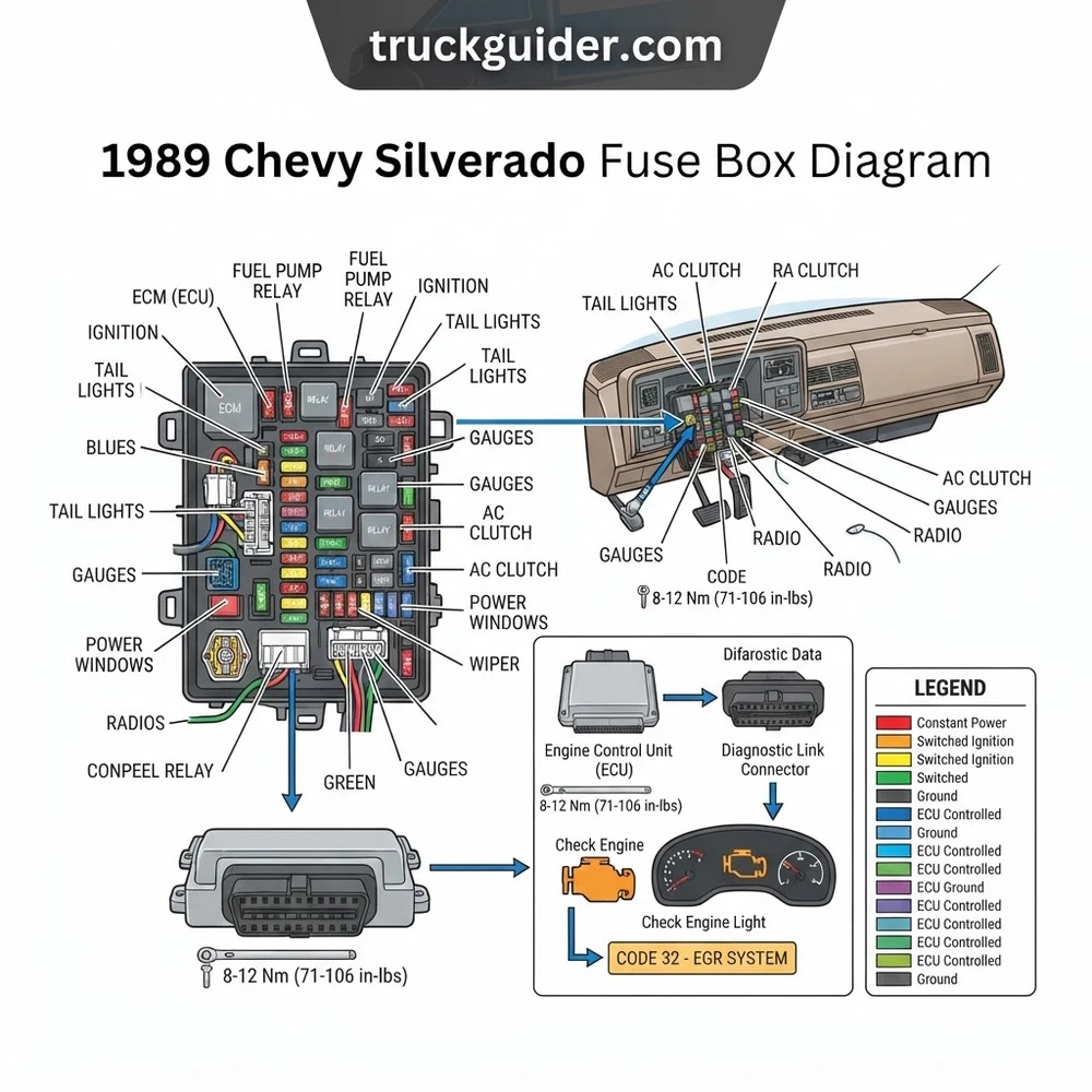
1989 Chevy Silverado Fuse Box Location and In-Cab Access
Recommended Best Deal Products


Locating the electrical heart of the GMT400 cab requires accessing the driver-side lower footwell. Unlike later platforms that feature an accessible side-dash panel visible only when the driver door is open, the 1989 Chevrolet Silverado positions its primary interior junction block directly beneath the dashboard, to the left of the steering column and emergency brake assembly.
To inspect the panel, remove the lower steering column sound insulator (often referred to as the knee bolster hush panel), which is secured with four 7mm hex-head screws. With this trim panel lowered, the main junction block faces downward toward the cab floorboard. The fuse block housing is molded from high-impact black nylon and contains standard blade-style receptacles alongside dedicated cavities for larger circuit protection hardware.
Directly adjacent to or clipped above the main fuse block is the GM Convenience Center. This modular sub-junction houses the horn relay, key-in ignition warning buzzer, seatbelt timer module, and the hazard warning flasher. Technicians frequently mistake the Convenience Center for an aftermarket alarm module due to its separate piggyback mounting.
The flasher units on the 1989 model are physically split across two locations. The round, aluminum-canister hazard warning flasher plugs directly into the lower right corner of the Convenience Center. In contrast, the turn signal flasher is mounted in a dedicated harness clip secured directly behind the instrument panel bracket, roughly three inches above the brake pedal pivot. Both units operate as thermal-bimetallic switches; when upgrading to modern LED exterior bulbs, both flashers must be swapped for non-load-dependent electronic flashers (such as the Tridon/Novita EL12) to prevent hyper-flashing or total operational failure.
Physical space around the in-cab junction box is tight. When servicing the terminals, utilize a dedicated ATO/ATC fuse puller or insulated long-nose pliers. Avoid using uninsulated steel pliers, as the unfused main battery feed stud on the backside of the junction block can be accidentally shorted against the structural dash frame, resulting in instantaneous harness arc damage.
1989 Chevy Silverado Fuse Box Diagram and Component Identification

The interior fuse panel on the 1989 Silverado utilizes industry-standard Delco-Remy electrical architecture. This panel accommodates fast-acting ATO/ATC blade fuses, along with Type I (auto-reset) and Type II (modified reset) metal-can circuit breakers designed for high-amperage auxiliary accessories.
Understanding circuit distribution requires knowing how battery positive (BATT) and ignition-switched power (IGN) enter the block. Battery power originates at the engine-compartment firewall junction, running through 10-gauge fusible links to supply full-time live cavities such as the stoplights, hazard flashers, horn, and cigarette lighter. Ignition-switched power is routed through the multi-pole steering column ignition switch to energize the HVAC blower motor, instrument cluster, and fuel injection sub-circuits only when the lock cylinder is rotated to the “RUN” or “CRANK” position.
| Position / Cavity Name | Rating (Amps) | Fuse Type | Wire Colors & Protected Circuits |
|---|---|---|---|
| ECM B | 15A | ATO / ATC | Orange (ORG): Engine Control Module constant battery memory, Fuel Pump Relay coil & pull-in contacts. |
| ECM I | 10A | ATO / ATC | Pink/Black (PNK/BLK): Electronic Spark Timing (EST) module, TBI Injector balance feeds, EGR solenoid. |
| GAUGES | 20A | ATO / ATC | Pink/Black (PNK/BLK): Cluster illumination, Fuel level sender, Oil pressure gauge, Brake failure light. |
| HTR – A/C | 25A | ATO / ATC | Brown (BRN): Climate control head, A/C compressor low-pressure cycling switch, Blower resistor bank. |
| WIPER | 25A | ATO / ATC | White (WHT) / Purple (PPL): Front wiper pulse board motor assembly, Washer pump solenoid. |
| STOP / HAZ | 20A | ATO / ATC | Orange (ORG) & White (WHT): Brake pedal switch, Hazard flasher relay, Center High-Mount Stop Lamp. |
| CTSY | 20A | ATO / ATC | Orange (ORG): Cab dome lamp, Under-dash courtesy lights, Cargo box light switch, Glovebox light. |
| TAIL LPS | 20A | ATO / ATC | Brown (BRN): Tail lamp assemblies, Front park/marker lights, License plate lamps, Side markers. |
| CRUISE / BACKUP | 20A | ATO / ATC | Dark Blue (DK BLU) / Light Green (LT GRN): Cruise control transducer module, Manual/Auto reverse switch. |
| RADIO | 10A | ATO / ATC | Yellow (YEL): Head unit ignition-switched power feed. |
| INST LPS | 5A | ATO / ATC | Dark Green (DK GRN): Dash backlighting via dimmer rheostat (cluster, HVAC panel, radio display). |
| CIG / CLK | 20A | ATO / ATC | Orange (ORG): Cigarette lighter element, In-dash clock power, ALDL diagnostic pin feed. |
| PWR ACC (Breaker) | 30A | Metal Can Breaker | Silver Can: Power door locks, Power seats, Tailgate glass release (Suburban/Blazer). |
| PWR WDO (Breaker) | 30A | Metal Can Breaker | Silver Can: Power window master control switches, Left and right window regulator motors. |
Adjacent to the fuse matrix, the 1989 panel features molded tap terminals labeled BAT, IGN, and ACC. These auxiliary spade terminals allow direct integration of optional accessories without wire splicing. The BAT tap provides unfused, direct battery power downstream of the main fusible link, while IGN provides power active exclusively in Key-On and Start positions. Always run an inline ATO fuse holder when drawing accessory power from these taps.
Diagnosing Blown Fuses, ECU Shorts, and Gauge Cluster Failures
Recommended Best Deal Products


Electrical issues on the 1989 Silverado often involve interdependent systems. A blown fuse rarely signifies a defective fuse element; rather, it indicates excess current caused by a downstream circuit short or failing actuator. Three distinct circuits account for the majority of severe electrical failures on this platform.
ECM B Fuse Rupture and Fuel Delivery Interruption
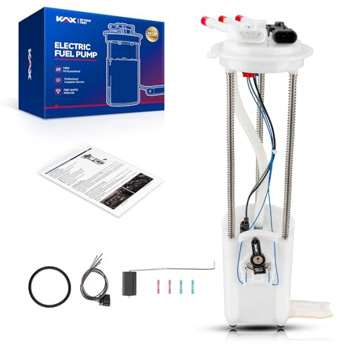
The 15-amp ECM B fuse delivers primary power to the Electronic Control Unit (ECU) constant memory and energizes the in-tank Delco electric fuel pump via the fuel pump relay. When this fuse blows, the engine cranks continuously without starting, and no check engine light illuminates during the bulb check. A classic GM failure mode involves the secondary fuel pump backup circuit.
According to factory Delco-Remy wiring specifications, GM engineered a failsafe: the engine oil pressure sending unit contains an internal parallel mechanical switch. If the fuel pump relay fails, or if the primary feed opens, oil pressure exceeding 4 PSI mechanically closes the internal switch contacts, routing power directly to the fuel pump. Consequently, if the oil pressure switch develops an internal direct short to ground through its sensor housing, it will instantly blow the ECM B fuse. If your ECM B fuse blows on start-up, unplug the three-wire oil pressure sender at the rear of the engine block near the distributor before condemning the fuel pump harness or ECU.
Never replace the 15A ECM B or 10A ECM I fuse with a higher-rated fuse (e.g., 25A or 30A). The ECU circuit traces on the internal PCB cannot handle extended overcurrent. Doing so will vaporize the internal ground traces inside the computer housing before the fuse blows.
Instrument Cluster Failures and Tail Light Ground Loops
The 20A GAUGES fuse and 20A TAIL LPS fuse frequently interact through shared chassis ground circuits. When the GAUGES fuse blows, all analog needles drop to zero, the alternator stops receiving its field excitation voltage (causing the charging system to fall to battery baseline ~12.2V), and the PRNDL display goes dark.
The most common cause of this fault originates at the rear lighting harness. The rear tail lamp circuit boards on 1988–1998 GM trucks feature exposed stamping traces that corrode over time. When water breaches the tail light housing, a bridge forms between the 12V running light trace and the chassis ground circuit. This creates an intermittent dead short that burns through the 20A TAIL LPS fuse. If corrosion is advanced, high-amperage current backfeeds through the cluster illumination dimmer circuit via the brown wire, instantly taking down the GAUGES circuit and setting diagnostic codes within the electronic control system.
Steering Column Ignition Switch Wear
Unlike modern vehicles with microprocessor-switched starting arrays, the 1989 Silverado uses a heavy mechanical sliding ignition switch located on top of the steering column jacket, actuated by an internal steel rod connected to the key lock cylinder. Over decades of cycling, the internal brass contacts wear out, introducing high contact resistance. This drops system voltage across the ECM I and HTR-A/C fuses, generating phantom diagnostic code 42 (Electronic Spark Timing bypass open) or code 54 (low fuel pump voltage) while making the truck shut off over bumpy terrain.
Testing 1989 Chevy Silverado Fuse Box Circuits Step-by-Step
Isolating circuit failures requires a systematic testing process using a heavy-duty 12-volt incandescent test light and an auto-ranging Digital Multimeter (DMM). Follow this technical sequence to pinpoint open circuits, high-resistance faults, and parasitic battery drains.
- Establish a Verified Chassis Ground: Connect the reference lead of your test light or DMM directly to the bare metal steering column support brace or the solid steel brake pedal bracket. Verify your ground by touching the probe tip to the hot constant battery post on the Convenience Center; the test light must illuminate brightly (or read >12.4V on a DMM).
- Perform In-Situ Blade Fuse Testing: Turn the ignition lock cylinder to the “RUN” position with the engine off. Without removing the ATO/ATC fuses from their sockets, place the sharp probe tip of the test light onto the exposed metallic test pads positioned on the left and right outer edge of each fuse face.
- Both pads light up: The fuse is intact and power is traversing through the circuit.
- One pad lights up, one is dead: The fuse element is open (blown). Replace the fuse after resolving the downstream short.
- Neither pad lights up: The circuit is switched off, the ignition switch contacts are worn, or the main power bus feed from the firewall is interrupted.
- Measure In-Circuit Voltage Drop: For circuits that demonstrate intermittent failure (such as dim instrument displays or sluggish wipers), set your DMM to the millivolt (mV) DC scale. Place your positive probe on one test pad of the fuse and the negative probe on the opposite pad while the circuit is operating under load. A voltage drop exceeding 50 millivolts (0.050V) across an ATO blade fuse indicates internal contact fatigue or high pin tension resistance within the fuse box terminal clips.
- Perform Parasitic Battery Drain Isolation: If the battery discharges overnight, turn off all accessories, extract the key, and close the cab doors (depressing the jamb switches). Disconnect the negative battery cable terminal. Insert your DMM set to the 10-amp DC scale in series between the negative battery post and the disconnected negative cable clamp.
- Wait 60 seconds for the ECM internal capacitors to settle. A normal draw for a 1989 Silverado should not exceed 35 milliamps (0.035A).
- If the draw exceeds 100mA, extract one fuse at a time from the in-cab fuse block while watching the meter display.
- When the meter drops to normal baseline upon pulling a specific fuse (commonly CTSY or CIG/CLK), you have isolated the specific harness branch containing the parasitic fault.
Factory Parasitic Draw Maximum: 30-40 mA
Maximum Allowable Ground Voltage Drop: < 0.10V DC
Minimum Fuel Pump Relay Control Voltage: 11.5V DC during engine cranking
Under-Hood Fusible Links and Firewall Junction Block Architecture
Recommended Best Deal Products


The interior fuse panel does not connect directly to the vehicle’s battery. Current must first transit the primary under-hood power distribution architecture, which differs significantly from modern under-hood fuse boxes containing Maxi-fuses or modern micro-relays.
On the 1989 Silverado, main power distribution centers on a multi-stud terminal block bolted to the passenger side firewall, shielded beneath a snap-on plastic cover. Heavy 10-gauge red leads route from the starter motor solenoid terminal stud up to this firewall junction. Circuit protection for these high-amperage feeds is managed by inline fusible links—special wire segments insulated with non-flammable Hypalon that are four American Wire Gauge (AWG) sizes smaller than the circuit wiring they protect.
| Platform Generation | Primary Power Distribution | Circuit Protection Hardware | Service Procedure |
|---|---|---|---|
| 1987 Squarebody (C/K) | Fender-well mounted distribution stud and starter solenoid block. | 16 AWG & 14 AWG Fusible links at starter and core support. Glass glass/ceramic fuses in-cab. | Requires manual splice and solder-shrink replacement of burned Hypalon link wires. |
| 1989 Silverado (GMT400) | Firewall-mounted multi-terminal junction block (pass. side). | Fusible links (16, 14, 12 AWG) powering internal ATO/ATC blade block and Convenience Center. | Inspect link elasticity; repair with exact gauge fusible wire using heat-shrink crimp barrels. |
| 1995–1998 Update (GMT400) | Engine-bay Underhood Fuse and Relay Center (driver side). | Maxi-fuses (20A–60A), mini blade fuses, and sealed micro-relays. Eliminates loose fusible links. | Modular component swapping; pull and replace Maxi-fuse cartridges without cutting wire. |
If your 1989 Silverado experiences total in-cab electrical failure (no headlights, no starter engagement, no cluster display), inspect the fusible links at the passenger side firewall junction. To diagnose a ruptured fusible link, firmly tug the wire lengthwise. Because the internal copper conductor melts while the Hypalon rubber outer casing remains intact, a blown fusible link will stretch like a rubber band under tension.
When servicing the firewall terminal studs, adhere strictly to the factory torque spec of 40 in-lbs (4.5 Nm). Over-tightening can crack the non-conductive plastic base plate, while under-torquing leads to high-resistance hotspots that mimic alternator charging failures.
1989 Chevy Silverado Fuse Box Diagram FAQs
Where is the fuel pump fuse located on a 1989 Chevy Silverado?
Unlike newer trucks equipped with a dedicated slot clearly labeled “FUEL PUMP,” the 1989 Silverado protects the fuel pump circuit via the ECM B (15-amp) fuse located inside the main in-cab fuse block. This fuse provides continuous battery power to the fuel pump relay coil and switched contacts. The physical fuel pump relay itself is mounted under the hood on the passenger side firewall beneath a plastic protective shield, positioned next to the electronic spark control module.
Why does my 20A GAUGES fuse blow whenever the truck is shifted into reverse?
This failure occurs when the backup lamp circuit experiences an active ground short. The 20A GAUGES fuse powers the reverse light circuit through the transmission switch. On manual transmissions, the backup light switch is threaded into the transmission case; on automatic transmissions (such as the 700R4), it is integrated into the neutral safety switch on the lower steering column. Look for melted insulation where the backup wire harness drops along the firewall down to the bellhousing, where it frequently contacts hot exhaust downpipes.
How does the 1989 ALDL diagnostic port receive power from the fuse box?
The 12-pin Assembly Line Diagnostic Link (ALDL) port—the predecessor to the OBD-II standard used to pull two-digit diagnostic codes via the “check engine” light flashing sequence—draws 12V battery reference power from the 20-amp CIG / CLK fuse. If this fuse is blown due to a jammed accessory in the cigarette lighter socket, scan tools or ALDL code-readers will fail to connect or establish serial communication with the vehicle’s ECU.
Can I swap the metal-can circuit breakers for standard ATO blade fuses?
You can physically insert an ATO blade fuse into the PWR ACC or PWR WDO cavities, but doing so compromises functional design. GM used thermal-cycling metal-can circuit breakers for power windows and door locks because these high-draw inductive motors produce momentary stall currents up to 28 amps when a window hits the top of its track. A standard 30A fast-acting blade fuse will suffer fatigue and rupture over repeated cycles, whereas a thermal breaker trips temporarily, cools down, and automatically resets itself.
Why does my A/C and heater blower motor only run on high speed?
When the climate control operates only on its maximum fan setting, the issue is not a blown fuse in the main junction box. The high-speed setting bypasses the cab fuse box entirely; it is fed directly by an under-hood 30-amp inline fusible link through an external high-speed relay. Lower fan speeds (Low, Medium-1, Medium-2) route through the 25-amp HTR-A/C in-cab fuse and pass through the blower motor resistor pack located in the HVAC housing behind the glovebox. If lower speeds fail while “High” operates, the thermal cut-off link within the resistor block has opened due to restricted cabin airflow or an aging, high-amperage blower motor.