1991 Chevy Silverado Fuse Box Diagram 2026: Installation Guide

The 1991 chevy silverado fuse box diagram shows component layout, connection points, and routing paths. Use it to identify parts, diagnose issues, and follow correct installation or repair procedures.
📌 Key Takeaways
- Understanding the 1991 chevy silverado fuse box diagram is essential for proper implementation
- Each component has a specific role and connection point
- Following safety guidelines prevents common mistakes
- This diagram serves as a reference for practical applications
- Regular review helps maintain accurate understanding
Tracing electrical gremlins on early fourth-generation C/K trucks requires an exact understanding of General Motors’ transitional wiring architecture. The 1991 model year sits at a critical mechanical intersection for the GMT400 platform: Throttle Body Injection (TBI) electronic engine management relies on early digital engine control unit (ECU) calibration, yet power distribution remains split between an analog in-cab junction panel, an engine-bay terminal stud, and fusible links. Whether you are chasing an intermittent no-start, hunting down parasitic battery drains, or diagnosing instrument cluster gauge failures, this technical wiring guide and circuit breakdown provides the exact pinouts, amperage thresholds, and testing procedures required to restore your electrical system to factory standard.
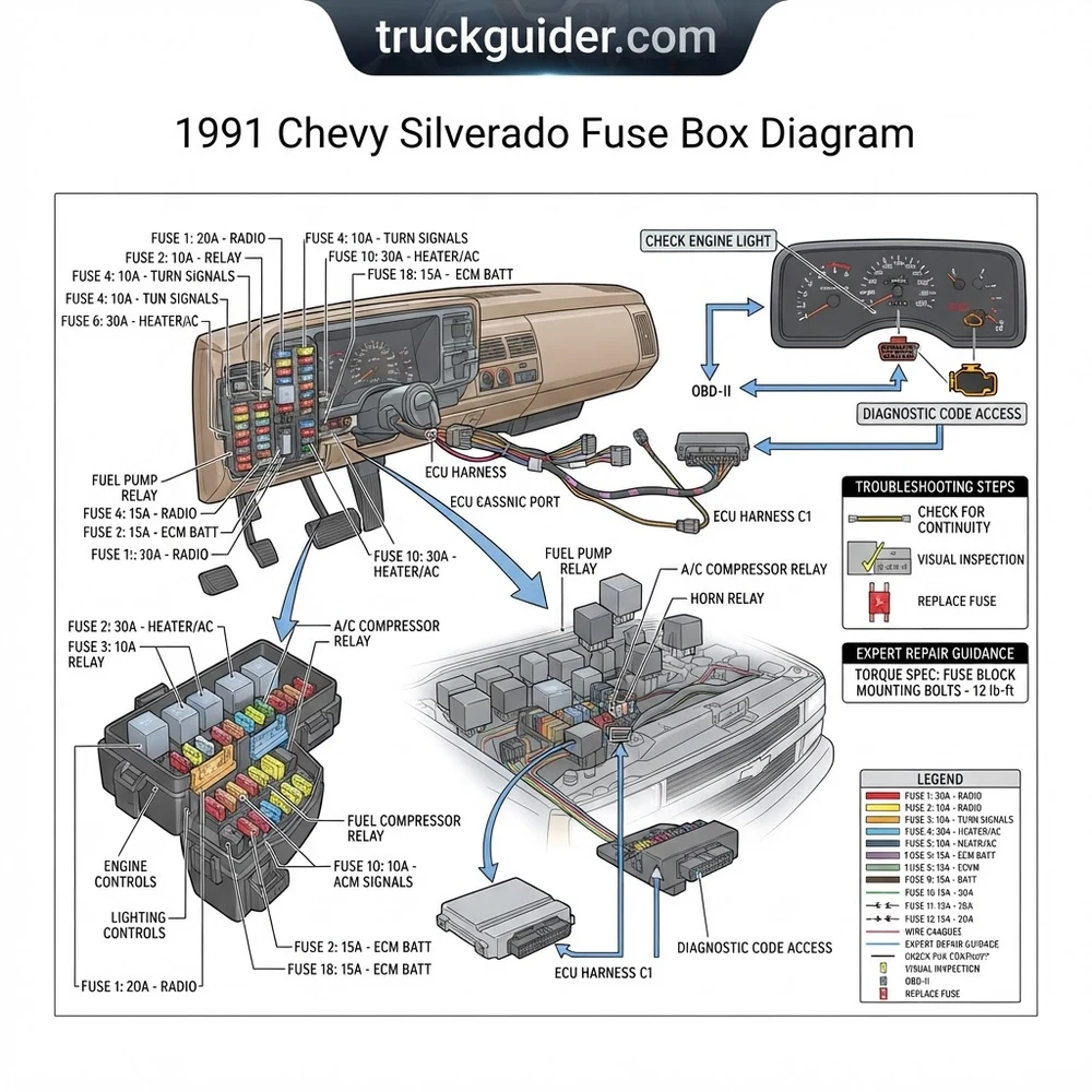
1991 Chevy Silverado Fuse Box Diagram and Cab Panel Locations
Recommended Best Deal Products


Diagnosing electrical faults on a 1991 Chevrolet C/K 1500, 2500, or 3500 platform requires navigating around a common misconception: the belief that all GMT400 trucks share an underhood power distribution center. If you are searching the engine bay for a black plastic fuse box containing mini-blades and square relays, you are looking for an assembly that does not exist on this truck. General Motors did not introduce an integrated underhood power distribution block until the major interior and electrical redesign of the 1995-1998 Chevy Silverado (Late GMT400) fuse box architecture.
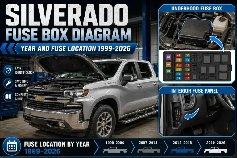
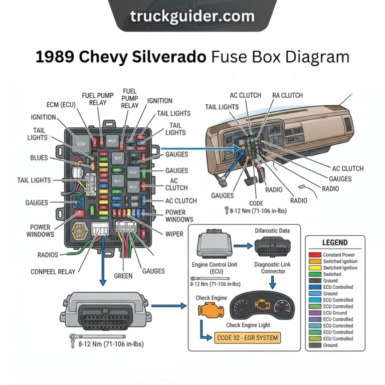
On your 1991 model, the primary interior fuse block serves as the single centralized junction for cab and chassis fuses. It is physically mounted under the far left side of the dashboard, directly against the inner firewall kick panel to the left of the brake and clutch pedal bracket. Accessing this panel requires removing a protective molded cover that snaps over the face of the block. If your truck still features OEM factory trim, the inside face of this removable cover contains a molded or silk-screened cavity legend matching the fuse assignments.
Because there is no underhood fuse box, GM split high-amperage power distribution across two distinct zones:
- The Interior Fuse Block: Manages standard ATO/ATC blade fuses for cabin accessories, lighting switches, heating, ventilation, and interior controls. It also houses mechanical flashers and thermal circuit breakers for heavy inductive loads.
- The Engine Compartment Junction Block / Stud: Located high on the passenger-side firewall (often shielded by a plastic protective shroud), this heavy-duty terminal junction acts as the main bus distribution point directly downstream from the positive battery cable. High-current accessories, auxiliary trailering harnesses, and the primary feeds into the cab originate from this copper stud.
- The Convenience Center: Positioned adjacent to the main interior fuse panel, tucked higher up behind the dash near the steering column, this auxiliary carrier plate houses plug-in modules, including the key-in/headlights-on warning chime, the horn relay, and the hazard flasher unit.
Never mistake the junction block on the passenger-side firewall for an aftermarket modification. That multi-stud terminal carries un-fused battery voltage straight from the starter solenoid and positive battery cable, distributing 12-volt potential to cabin circuits via dedicated inline fusible links.
To avoid diagnostic errors, ensure you are referencing documentation specifically engineered for 1988–1994 GMT400 cabs. Attempting to match wire colors or circuit functions from late-model 1995–1998 wiring schematics will lead to blown circuits, as harness routing and wire gauge specifications were completely overhauled when GM transitioned from early TBI systems to late-generation central sequential fuel injection platforms.
1991 Chevy Silverado Fuse Box Diagram: Circuit Ratings and Cavity Map

The interior fuse block on your 1991 Silverado utilizes standard, colored ATO/ATC blade fuses, complemented by metal can thermal circuit breakers for high-cycling inductive circuits. Power across this panel is divided internally into two primary buses: battery hot (constant 12-volt supply available at all times) and ignition-switched power (energized only when the ignition key is turned to RUN or ACCESSORY positions via the steering column ignition switch). Below is the comprehensive circuit reference table matching OEM factory service manual designations.
| Cavity Label | Rating | Bus Type | Protected Components & Circuits |
|---|---|---|---|
| ECM B | 20 Amp (Yellow) | Battery Constant | Electronic Control Module (ECU memory), Electric Fuel Pump Relay, Oil Pressure Switch bypass feed |
| ECM 1 | 10 Amp (Red) | Ignition Switched | Engine Control Module (ECU ignition feed), TBI Fuel Injector circuits, EST distributor module |
| WIPER | 25 Amp (White) | Ignition Switched | Windshield Wiper Motor assembly, Pulse Wiper module, Windshield Washer pump |
| GAGES | 10 Amp (Red) | Ignition Switched | Instrument Cluster, Oil Pressure gauge, Coolant Temperature gauge, Voltmeter, Fuel gauge, Brake Warning Lamp, DRL relay |
| HTR – A/C | 25 Amp (White) | Ignition Switched | HVAC Blower Motor switch, Blower Resistor pack, A/C Compressor Clutch control head |
| TAIL LP | 20 Amp (Yellow) | Battery Constant | Tail lamps, Parking lamps, Side marker lamps, License plate lamps, Instrument cluster illumination backlighting |
| STOP / HAZ | 20 Amp (Yellow) | Battery Constant | Brake light switch, Hazard warning flasher, Third brake light (if equipped) |
| HORN / DM | 20 Amp (Yellow) | Battery Constant | Horn relay trigger, Dome lamp, Courtesy floor lamps, Cargo light, Key-in warning chime |
| RADIO | 10 Amp (Red) | Ignition Switched | Radio receiver head unit, Audio cassette player, Clock display circuit |
| CLK / LTR | 20 Amp (Yellow) | Battery Constant | Cigarette lighter receptacle, Radio constant memory feed, 12V auxiliary power port |
| BRAKE | 10 Amp (Red) | Ignition Switched | Rear-Wheel Anti-Lock (RWAL) brake computer module, ABS indicator circuit |
| TURN / B/U | 20 Amp (Yellow) | Ignition Switched | Turn signal flasher, Reverse / Back-up lamps, Transmission range switch input |
| PWR ACC | 30 Amp Breaker | Battery Constant | Metal Can Thermal Circuit Breaker: Power Door Locks, Power Windows relay supply |
| IGN UNLK | 30 Amp Breaker | Ignition Switched | Metal Can Thermal Circuit Breaker: Power Windows master switch supply circuit |
In addition to blade fuses, your fuse block incorporates two cylindrical flasher sockets. The socket on the lower left face of the block manages the turn signal flasher. The hazard flasher, however, is frequently mounted remotely on the Convenience Center. These flasher sockets require a standard two-prong thermal or electronic flasher unit (such as GM part number 560416 or equivalent tridon/Bussmann 552). If you upgrade tail lights to LED units, these thermal flashers must be swapped for electronic, zero-load flasher relays to prevent hyper-flashing conditions.
Never replace the 30-amp PWR ACC metal can thermal circuit breaker with an ordinary 30-amp ATO blade fuse. Power window and power door lock actuators draw heavy inductive stall currents that cause nuisance tripping. Installing a standard blade fuse can result in fuse fatigue, melt the fuse block plastic housing, or cause harness damage under sustained load.
Firewall Fusible Links, ECU Power Feeds, and the Convenience Center
Recommended Best Deal Products

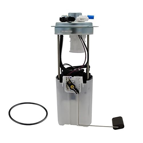
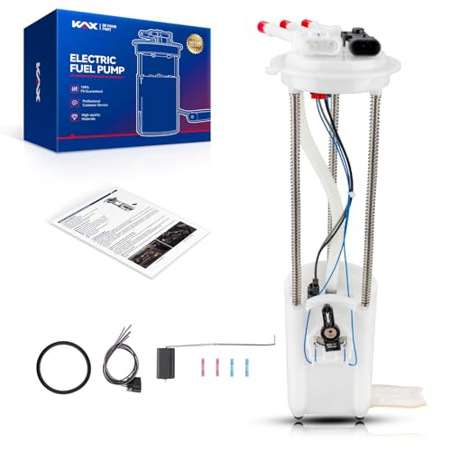
While the interior fuse panel distributes circuit protection for the cabin, vital engine functions rely on protection mechanisms situated on the passenger side of the engine compartment firewall and down near the starter motor. Understanding this layout is essential when facing complete electrical failure or intermittent fuel delivery.
General Motors engineers relied heavily on fusible links rather than standard maxi-fuses during this production era. A fusible link is a four-gauge-size smaller section of wire with specialized non-flammable Hypalon insulation, designed to intentionally burn out and sever the circuit in the event of an extreme dead short before the main engine harness catches fire. On your 1991 Silverado, there are four primary fusible links to verify:
- Starter Solenoid Links (2): Two heavy fusible links (16-gauge and 14-gauge) tap off the 3/8-inch main battery lug on the starter solenoid. One powers the cab’s primary ignition switch harness, while the second feeds auxiliary charging and alternator output back into the system.
- Firewall Junction Block Links (2): Positioned at the passenger-side firewall stud, these links protect the high-current blower motor relay circuit and the TBI fuel injection harness feeds.
When torquing the starter battery positive terminal nut, observe an OEM torque spec of 90 lb-in (10 Nm). For the passenger-side firewall junction block terminal stud nuts, apply a strict torque spec of 35 lb-in (4 Nm) to avoid cracking the structural bakelite backing plate.
The TBI (Throttle Body Injection) Fuel Pump Relay is mounted on a metal bracket high on the passenger-side firewall, alongside the RWAL brake control relay. This relay routes constant 12-volt battery power (protected by the ECM B 20A fuse in the cab panel) to the in-tank electric fuel pump. Crucially, GM built an electrical bypass directly into the engine block: the mechanical oil pressure switch/sender located near the distributor base or above the oil filter pad contains a secondary internal switch. When cranking builds engine oil pressure above 4 psi, this switch contacts internally and sends unswitched battery power straight to the fuel pump. If the primary fuel pump relay burns out, your truck will still start, but it will require extended, grueling cranking cycles until oil pressure reaches 4 psi to trigger pump activation.
Finally, under the driver’s dash lies the Convenience Center. This plastic matrix block simplifies multi-component grounding and audio alerts. It houses the horn relay, key-in chime module, and the daytime running light (DRL) diode assembly on Canadian models. When tracking phantom audio buzzer sounds or horn failures, pull the modular components directly from this sub-carrier panel rather than disassembling the main fuse block.
Diagnostic Code Faults, Check Engine Light Triggers, and Circuit Failures
The 1991 C/K platform operates under General Motors’ early Assembly Line Diagnostic Link (ALDL) OBD-I architecture, not the modern OBD-II standard introduced industry-wide in 1996. Diagnosing an illuminated check engine light requires understanding how fuse failures translate into OBD-I diagnostic codes and component breakdowns.
Reading a diagnostic code on this vehicle does not require an advanced digital OBD-II scanner. Beneath the driver’s dash, locate the rectangular 12-pin ALDL diagnostic port. Using a basic jumper wire or metal paperclip, bridge terminal pin A (top right, chassis ground) to terminal pin B (directly left of pin A, diagnostic test terminal). Turn the ignition switch to the ON position without starting the engine. The instrument cluster check engine light will begin flashing in sequence:
- Flashing once, pausing, then flashing twice (Flash… Flash-Flash) confirms Code 12, which simply establishes that the ECU system diagnostic routine is functioning properly. Each code repeats three times.
- If the ECM B fuse is blown, the check engine light will not illuminate at all because the ECU lacks internal keep-alive battery potential.
- If the ECM 1 fuse blows during operation, the ECU loses its switched RUN/CRANK reference signal. This results in an immediate engine stall, throwing a hard crank/no-start condition with zero check engine light illumination and no fuel injector pulse.
Another frequent failure occurs within the headlight circuitry. Drivers often report headlights blinking off and on rhythmically when driving at night. Technicians unfamiliar with the GMT400 layout waste hours inspecting exterior harnesses or suspecting burned ATO/ATC blade fuses. In reality, the exterior headlamps bypass the interior fuse block entirely. The dash-mounted headlight switch contains an internal, self-resetting bi-metallic thermal circuit breaker. When aftermarket halogen sealed-beam bulbs or high-draw driving lights are installed, total current draw exceeds the switch’s factory thermal threshold. The breaker trips, disconnects the lamps, cools down over several seconds, reconnects the circuit, and repeats this cycle continuously. Correcting this requires installing an auxiliary relay kit rather than modifying the fuse box.
Diagnostic codes can also stem from harness ground degradation. The engine’s coolant temperature sensor (CTS)—critical for fuel mixture trimming and ECU closed-loop operation—shares harness grounding pathways with the gauge cluster. If coolant flow around the intake manifold thermostat housing develops internal scale, or if the thermostat ground lug on the intake manifold stud loosens, the sensor reports skewed resistance values. The ECU responds by triggering an intermittent Code 14 (high coolant temp) or Code 15 (low coolant temp), upsetting ignition timing advance and triggering high idle conditions.
Similarly, unexpected distributor timing chain slack or improper base ignition timing setup will trigger a Code 42 (Electronic Spark Timing / EST circuit failure). When setting base timing to the factory spec (0° TDC on standard 5.7L VIN K engines), you must unplug the single-wire tan/black EST bypass connector tucked beneath the passenger-side firewall plastic relay cover. If this wire grounding short-circuits to the firewall, the ECM 1 fuse can fail instantly upon ignition switch cycling.
Testing the 1991 Chevy Silverado Fuse Box Diagram Circuits in 5 Steps
Recommended Best Deal Products


Troubleshooting vintage copper-terminal fuse blocks requires precise diagnostic techniques to avoid bending the female leaf terminals inside the block. Follow this verified five-step process to trace voltage drops, open circuits, and dead shorts.
- Establish Ground and Perform Visual Integrity Check: Clamp the ground lead of an automotive digital multimeter (DMM) or incandescent 12-volt test light directly to a solid, bare chassis ground. Excellent locations include the parking brake pedal bracket bolts or the bare steering column mount studs. Avoid clamping to painted trim screws. Inspect the face of the interior fuse block for heat discoloration, melted terminal plastic, or corrosion caused by leaking windshield seal gaskets.
- Test the Constant Battery Bus (Key OFF): With the truck’s ignition switch set to OFF, probe the exposed metal test tabs on the back of each ATO/ATC blade fuse. Cavities such as ECM B, TAIL LP, STOP/HAZ, and HORN/DM must show battery voltage (12.4 to 12.6 volts minimum). Verify that both top and bottom test tabs on each fuse illuminate the test light or report identical DMM voltages. If one tab has 12V and the opposite tab shows 0V, the fuse element is blown.
- Test the Switched Bus (Key ON / Engine OFF): Insert the key and cycle the ignition switch to the RUN position. Re-test previously dead cavities, specifically ECM 1, WIPER, GAGES, and TURN/B/U. If an entire vertical bank of fuses fails to power up, suspect a failed ignition switch harness contact down on the steering column base, or check for a burnt 16-gauge fusible link down at the starter solenoid terminal harness.
- Conduct In-Circuit Voltage Drop Tests: For circuits experiencing intermittent or sluggish operation (such as dim instrument clusters or slow blower fans), measure operational voltage drop. Turn the circuit switch ON. Place the positive DMM probe on the battery positive terminal, and the negative probe on the load-side test tab of the corresponding fuse. A reading exceeding 0.3 volts reveals excessive resistance in the primary feed harness upstream of the fuse box.
- Isolate Persistent Dead Short Circuits: If a replacement fuse blows the instant it is pushed into the socket, do not continue inserting fresh fuses. Remove the blown fuse and connect a 12V incandescent test light across the two exposed terminals inside the empty fuse block cavity. With a short circuit present, the test light will burn at full brightness. Disconnect downstream harness connectors one at a time (e.g., unplugging tail lamp pigtails or the fuel pump sender harness). The exact moment the test light turns completely off, you have isolated the specific harness section containing the short to ground.
1991 Chevy Silverado Fuse Box Diagram and Electrical Troubleshooting FAQ
Where is the fuel pump fuse located on a 1991 Chevy Silverado?
The fuel pump is protected by the ECM B 20-amp yellow blade fuse located in the primary interior fuse panel under the driver’s dash. This circuit provides continuous battery voltage to the fuel pump relay mounted on the passenger-side engine firewall. Power then flows from the relay through a tan/white stripe wire along the chassis frame rail back to the in-tank electric pump assembly.
Why does my truck still run if the TBI fuel pump relay is removed?
Your 1991 Silverado utilizes a fail-safe secondary circuit integrated directly into the oil pressure switch. Mounted on the engine block, this switch contains an independent set of internal contacts wired in parallel with the fuel pump relay. As long as engine cranking creates more than 4 psi of oil pressure, the mechanical switch closes, sending 12-volt battery power directly to the electric fuel pump. A bad relay will cause hard starting, but the engine will continue running once oil pressure builds.
Can I convert my 1991 Silverado electrical system to standard OBD-II?
No, the 1991 C/K platform uses GM’s proprietary 12-pin ALDL (Assembly Line Diagnostic Link) OBD-I architecture operating on a slow 160-baud serial data stream. The factory 1227747 or 16197427 ECU cannot communicate using modern OBD-II protocols. Converting the vehicle to true OBD-II compliance requires swapping in a complete powertrain and harness from a 1996 or newer Vortec truck, including the crank position sensor, dual oxygen sensors, and late-model black-box or 0411 powertrain control module (PCM).
Why does my instrument panel gauge fuse (GAGES 10A) keep blowing?
The 10-amp GAGES fuse powers several distinct sub-assemblies through ignition-switched voltage, including the gauge cluster indicators, daytime running light modules (if equipped), reverse light switch, and the alternator exciter lead. A very common failure point is the reverse light switch harness down at the transmission casing (manual transmissions) or the neutral safety switch (automatic transmissions). Exhaust heat frequently melts the wire insulation against the crossover pipe, creating a dead short to ground that blows the GAGES fuse instantly when shifting into reverse.
What causes complete power loss inside the cab while the battery is fully charged?
When you have a charged 12.6V battery but turn the key to find the cab completely dark with zero power to the interior fuse panel, the issue is almost always a severed fusible link. Inspect the two fusible links attached to the 3/8-inch battery stud down on the starter solenoid. Grab each link wire firmly and pull; if the internal metal wire core has burned out, the external Hypalon insulation will stretch like a rubber band, revealing an internal open circuit that cuts all un-switched cab power.
Step-by-Step Guide to Understanding the 1991 Chevy Silverado Fuse Box Diagram
Identify the main components in the diagram
Locate connection points and relationships
Understand the flow or sequence shown
Apply the knowledge to your specific situation
Verify your understanding matches the diagram