1991 Ford Ranger Fuse Box Diagram: 2026 Repair Guide

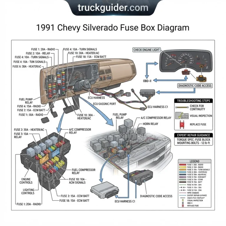
The 1991 Ford Ranger fuse box mounts under the dashboard to the left of the steering column, behind a pull-down plastic cover. An auxiliary high-current power distribution box sits in the engine bay near the starter relay, routing power via black/orange leads to the fuel pump relay, ECU, and ignition switch.
📌 Key Takeaways
- Standard blade-type ATC fuses range from 10A to 30A, with heavy 60A maxi-fuses handling alternator output and ECU power feed.
- The interior cab fuse panel protects low-amperage accessories, while the underhood distribution box safeguards engine management and relays.
- Maintain a baseline of 12.6V during testing; apply a torque spec of 10-13 lb-ft to battery cable clamp terminals to avoid voltage drops.
- Corrosion inside the underhood EEC-IV relay connector pins is the primary failure point causing intermittent no-starts.
- Swap individual fuses and relays as a DIY fix, but consult a professional auto electrician if melted plastic indicates a dead short in the harness.
The electrical architecture of the 1991 Ford Ranger bridges analog vehicle wiring with the first wave of computerized powertrain controls. Operating on Ford’s proven EEC-IV engine management architecture, the electrical framework isolates low-amperage interior accessories inside an in-cab junction panel while managing high-amperage powertrain circuits through fender-mounted relays and fusible links. Navigating this architecture requires a thorough understanding of circuit layouts, terminal assignments, and downstream loads. Whether troubleshooting an uncommanded power drop to the fuel injectors, hunting down an intermittent instrument cluster failure, or isolating an ignition switch feed, this reference guide details the component layouts, wire colorations, and diagnostic routines necessary to service the 1991 Ford Ranger electrical system to factory standard.
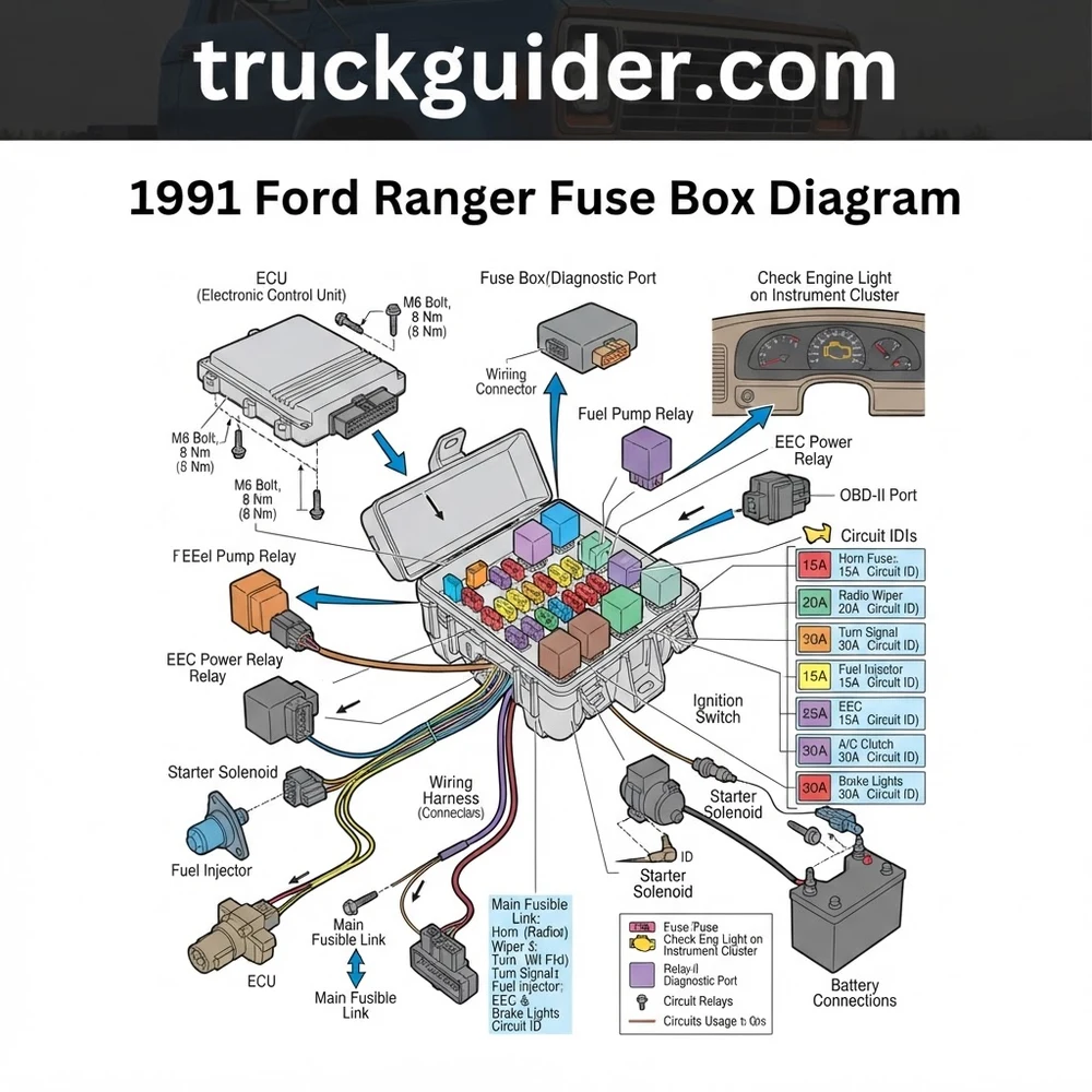
1991 Ford Ranger Fuse Box Diagram and In-Cab Circuit Protection
Recommended Best Deal Products


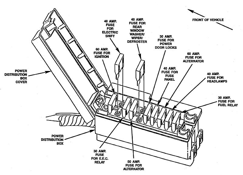
The interior fuse block on the 1991 Ford Ranger serves as the primary distribution nexus for non-engine accessories, lighting, safety systems, and switched ignition bus lines. Accessing and reading this panel correctly requires familiarity with its structural mounting location, fuse form factors, and distinct terminal numbering systems.
In-Cab Fuse Block Physical Layout and Orientation
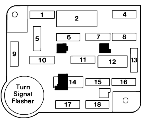
The interior junction panel is mounted underneath the driver-side dashboard, situated directly to the left of the steering column alongside the vehicle kick panel. To access the fuses, pull down the textured plastic lower dash trim panel by releasing the retention thumb-screws or spring-steel retaining clips. Once opened, the fuse block presents a rectangular grid layout containing standard automotive plug-in blade positions, flanked by heavy-duty cylindrical sockets engineered to secure flasher canisters and a thermal circuit breaker.
In accordance with OEM specifications, the 1991 model year cabin junction panel utilizes standard ATO/ATC fast-acting automotive blade fuses (rated up to 32V DC). Each slot is stamped with an integer designation (1 through 18). Constant battery voltage (Hot at All Times) is supplied to dedicated bus bars on the rear of the block directly from the starter motor relay stud via under-hood fusible links, while accessory-switched voltage (Hot in ACC or RUN) and ignition-switched voltage (Hot in RUN or START) are routed through the steering column ignition switch assembly.
| Fuse # | Amp Rating | Color Code | Power Condition | Protected Circuits and Downstream Loads |
|---|---|---|---|---|
| 1 | 15A | Light Blue | Hot at All Times | Stoplamps, hazard warning flashers, anti-lock brake module keep-alive feed |
| 2 | — | — | — | Open / Unused terminal position |
| 3 | 15A | Light Blue | Hot in RUN | Backup lamps, electronic 4WD control module, daytime running lights (DRL) relay |
| 4 | 15A | Light Blue | Hot at All Times | Dome lamp, cargo courtesy light, cargo switch, visor vanity mirrors, electronic radio clock memory |
| 5 | 15A | Light Blue | Hot in RUN or ACC | Windshield wiper motor, interval wiper control module, washer pump fluid motor |
| 6 | 20A | Yellow | Hot at All Times | Cigar lighter, auxiliary 12V power point, diagnostic data link connector power |
| 7 | — | — | — | Open / Spare option cavity |
| 8 | — | — | — | Open / Unassigned position |
| 9 | 30A | Light Green | Hot in RUN | Heater blower motor assembly, air conditioning function selector switch assembly |
| 10 | 15A | Light Blue | Hot at All Times | Exterior park lamps, side marker lamps, taillights, license plate lamps, cluster illumination |
| 11 | 15A | Light Blue | Hot in RUN or ACC | Radio power, digital cassette player, premium sound amplifier enable wire |
| 12 | — | — | — | Open / Dealer-installed accessory slot |
| 13 | 15A | Light Blue | Hot at All Times | Horn relay coil and contacts, steering column horn slip ring switch |
| 14 | — | — | — | Open / Factory auxiliary circuit |
| 15 | — | — | — | Open / Unused terminal position |
| 16 | 30A CB | Metal Can | Hot in RUN or ACC | Power windows master switch, power door locks switch contacts (Circuit Breaker) |
| 17 | 10A | Red | Hot in RUN | Turn signal flasher, speed control amplifier, rear anti-lock brake (RABS) module |
| 18 | 10A | Red | Hot in RUN or START | Instrument cluster warnings, tachometer, oil pressure gauge, coolant temp gauge |
ATO/ATC Blade Fuses and Internal Circuit Breakers
The 1991 Ford Ranger relies strictly on genuine ATO/ATC plastic-bodied fuses featuring zinc terminals and standard 0.205-inch blade spacing. Circuit 16 departs from sacrificial fuses by implementing a cycling, bimetallic 30-amp internal circuit breaker packaged in a rectangular metal canister. Under overcurrent events—such as frozen window regulators or mechanical binding in the power door lock solenoids—the internal bimetal strip heats and deflects, opening internal silver contacts to interrupt continuity.
Once the excessive electrical load is removed and the bimetal substrate cools down, the contacts reset automatically. If your power windows fail completely under heavy continuous cycling but restore function after two minutes of rest, the thermal circuit breaker is operating as designed to protect harness insulation from thermal melting.
Never replace the metal-cased cycling circuit breaker in cavity 16 with a standard 30-amp blade fuse. High inrush currents typical of stalled DC window motors will rupture a standard fuse instantly, whereas sustained overcurrent across a jumper wire risks catastrophic dash wiring harness fire.
Turn Signal and Hazard Flasher Unit Operations
Independent cylindrical flashers govern direction indication and emergency illumination. The primary turn signal flasher mounts directly to the front face of the lower interior fuse block assembly. Powered downstream of Fuse 17 (10A) under key-on conditions, this dual-terminal electro-mechanical thermal flasher relies on circuit resistance from two active 1157 or 2057 exterior indicator bulbs to establish proper heat cycling. Installing LED retrofit bulbs without load resistors causes the flasher to hyper-flash or remain constantly illuminated without cycling.
Conversely, the hazard flasher unit plugs into a dedicated harness pigtail situated immediately behind the fuse box superstructure or clipped to the upper dashboard cross-brace. Powered via Fuse 1 (15A) directly from constant battery voltage, the hazard flasher utilizes a variable-load internal coil designed to oscillate evenly whether driving two vehicle lamps or four lamps plus an attached utility trailer.
Under-Hood Relays, Fusible Links, and ECU Power Distribution
While the cabin panel handles convenience and interior functions, all heavy-draw powertrain, starter motor, and engine control management is managed within the engine bay. The 1991 Ford Ranger does not feature an integrated under-hood plastic fuse box (Power Distribution Box); instead, it utilizes isolated high-amperage relays and calibrated fusible links.
Starter Motor Relay Solenoid and High-Amp Fusible Links
The central hub of under-hood battery power distribution is the fender-mounted starter relay solenoid, positioned on the passenger-side inner fender apron directly aft of the battery tray. The heavy copper battery-side threaded stud (+12V DC) acts as the source tap for every primary circuit in the vehicle, excluding the direct high-current positive cable running to the starter motor armature.
Starter Motor Relay Stud Nut Torque Spec: 45–60 in-lbs (5.1–6.8 Nm). Over-torquing will fracture the phenolic plastic end cap, causing intermittent complete vehicle blackouts and voltage drop faults.
Branching off this main battery post are multiple calibrated fusible links. These are short sections of hypalon-insulated wire manufactured four American Wire Gauge (AWG) sizes smaller than the copper circuit conductors they protect. In the event of a dead short to ground:
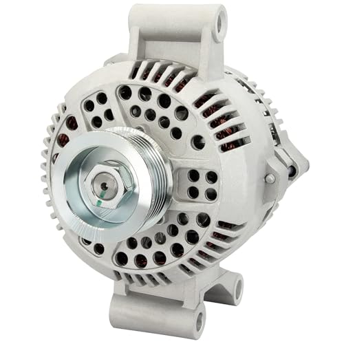
- Fusible Link A (16-gauge, Blue): Protects alternator charging feed (Circuits 36 & 38) connecting to the internal regulator and instrument cluster amp light.
- Fusible Link B (18-gauge, Brown): Feeds the cabin fuse panel bus bars (Circuits 37 & 152), providing current for headlamps, ignition switch input, and interior accessories.
- Fusible Link C (20-gauge, Rust/Orange): Shields the EEC-IV electronic control assembly power relay and solid-state primary engine management circuits.
- Fusible Link D (16-gauge, Blue): Dedicated high-capacity link delivering continuous +12V DC power to the auxiliary heater blower relay and optional high-draw air conditioning circuitry.
EEC-IV Computer and Electric Fuel Pump Relay Integration
Powertrain electronics depend on two plastic-housed Bosch-style mini-relays mounted along the passenger-side inner fender skirt or slotted within an auxiliary dual-relay bracket adjacent to the air cleaner assembly. Proper identification depends on connector shell pigmentation:
- EEC Power Relay (Brown Connector Socket): Receives battery-positive voltage through a 20-gauge fusible link. When the ignition cylinder is rotated to RUN, terminal 86 is energized by the ignition switch via a Red/Light Blue trace wire. The internal electromagnetic coil snaps contacts 30 and 87 closed, broadcasting continuous +12V operating voltage to pin 37 and pin 57 of the Electronic Control Unit (ECU), alongside the heated exhaust gas oxygen (HEGO) sensor heaters, fuel injector common rails, and the TFI-IV ignition module.
- Fuel Pump Relay (Green Connector Socket): Fed constant battery current on pin 30 via an independent under-hood fusible link. Pin 86 receives key-switched power from the activated EEC Power Relay. Ground control for pin 85 is modulated directly by Pin 22 of the powertrain computer. When the key is turned ON, the ECU grounds Pin 22 for exactly 1.8 to 2.0 seconds to prime the high-pressure fuel rail. It then opens the ground pathway until it detects continuous engine rotation pulses generated by the Hall-effect stator inside the distributor.
Evolution to 1993+ Second-Generation Power Distribution Centers
Beginning in the 1993 model year, Ford redesigned the Ranger line with a fully consolidated engine bay Power Distribution Box (PDB). This second-generation platform eliminated loose, fender-hung fusible links in favor of color-coded Maxi-fuses (30A, 40A, 50A, 60A) and consolidated mini-relays into a water-resistant modular box. Mechanics referencing 1991 Ranger wiring must take care not to consult 1993 or newer manuals, as the under-hood layout, terminal indexing, and downstream short-circuit protection diverge significantly.
Common 1991 Ford Ranger Fuse Box Diagram Electrical Faults
Recommended Best Deal Products


When electrical subsystems fail on the 1991 Ranger, issues rarely originate within the fuse block base itself. Instead, physical stress, vibration, corrosion, and downstream short circuits manifest as recurring blown fuses or relay malfunctions. The following fault paths represent primary failure modes identified across field service records.
- No-Start Condition via Inertia Fuel Shutoff Switch Activation: If the vehicle cranks vigorously without starting, but the green fuel pump relay clicks correctly, the mechanical inertia fuel shutoff switch has likely tripped. Located inside the passenger-side footwell, positioned high on the firewall transmission tunnel beneath the carpet edge, this switch contains a steel ball held by a permanent magnet. Physical impacts, hard road shock, or contact can displace the ball, opening the circuit between the fuel pump relay and the high-pressure fuel pump assembly. Reset the circuit by depressing the red top button until an audible latch confirms continuity.
- Starter Solenoid Heat Soak and Intermittent Cranking Blackout: High ambient engine bay temperatures degrade the inner phenolic casing and internal contact disk of the fender-mounted starter relay solenoid. A symptom of this failure is a sharp single click with an immediate drop in total vehicle electrical power. The sudden heavy draw through oxidized terminal posts creates massive resistance, simulating a blown master fusible link. Wire-brushing the solenoid studs down to bare copper and applying dielectric compound resolves minor voltage drops; persistent failures require unit replacement.
- Parasitic Battery Draw through the Glove Box / Under-Hood Lamps: Parasitic battery draws that deplete power within 48 to 72 hours frequently trace to the under-hood mercury tilt switch or the glove box plunger switch on Circuit 4 (15A Fuse). A failing mercury switch completes circuit ground even when the hood is fully latched. Isolating the draw requires connecting a digital multimeter in series between the negative battery terminal and disconnected ground cable, followed by pulling interior fuses one by one until current drops below 35 milliamps (0.035A).
- EEC Power Relay Failure Yielding Crank-No-Start and Dead Dashboard Indicators: A sudden failure of the brown EEC power relay cuts operational current to the ECU. When this occurs, the fuel pump will not prime, the fuel injectors remain inactive, the ignition system ceases spark output, and the instrument cluster red Malfunction Indicator Lamp (Check Engine Light) fails to illuminate when cycling the ignition key to the ON position. If your Check Engine Light fails its bulb-check sequence upon turning the key to RUN, the ECU lacks primary operational power.
- Gauge Fluctuation from Engine Ground Chafing at the Timing Chain Cover: The instrument cluster depends on steady electrical grounds and intact sensor harnesses running across the front engine harness loom. The harness passes directly over the timing chain cover and water pump assembly on both the 2.3L Lima inline-four and 2.9L/4.0L Cologne V6 engines. Decades of vibration can wear through the protective corrugated split loom, driving the oil pressure sender wire or coolant temperature wire directly against the metal casting. This fault pins the dash gauges to maximum limit or triggers erratic instrument readings without blowing a primary fuse.
For detailed ignition coil triggers and distributor Hall-effect failures, review our diagnostic teardown on TFI-IV ignition module troubleshooting to systematically trace primary switched power drops from the cabin ignition switch.
Diagnosing Circuit Faults and Check Engine Light Codes
Diagnosing intermittent electrical faults or dead circuits requires a structured methodology using a digital multimeter (DMM) and a 12V incandescent test light. Follow this diagnostic sequence to isolate short circuits, verify system power feeds, and extract diagnostic trouble codes.
- Examine High-Stress Fusible Links: Connect your DMM black lead to the negative battery post. Set the meter to DC Volts. Probe the downstream output eyelets of the fusible links clustered on the passenger-side starter motor relay terminal. You must measure clean battery voltage (+12.4V to +12.6V DC). Lightly stretch each fusible link wire by hand; a blown fusible link melts its internal copper core while leaving the elastic outer hypalon insulation intact, creating a rubbery, stretched feel under tension.
- Inspect In-Cab ATO/ATC Blade Fuses with a Logic Test Light: Ground your test light clamp to the bare steel brake pedal bracket beneath the dash. Rotate the ignition key to RUN. Touch the probe tip to both exposed metal test tabs on the rear face of each fuse without removing the fuse from the socket. A functioning fuse illuminates the test light on both sides. Illumination on one side only confirms an open, blown fuse element. Lack of light on both tabs indicates the entire upstream circuit is unpowered (e.g., an unswitched ignition bus or faulty ignition switch).
- Verify Inertia Switch Circuit Voltage Drop: If you suspect fuel delivery faults, peel back the passenger footwell carpet to access the two-pin inertia switch connector. Probe the Dark Green/Yellow stripe wire with your DMM back-probe adapter while an assistant cranks the engine. The meter must register battery voltage for the two-second priming burst or during continuous cranking. A reading below 10.5V DC indicates high resistance upstream within the fuel pump relay socket contacts or a degrading fusible link.
- Check Oil Pressure and Temperature Circuits on the Instrument Bus: If cluster gauges fail simultaneously, inspect Fuse 18 (10A). If the fuse is intact, disconnect the single-wire slide terminal at the engine oil pressure sender (located near the oil filter adapter on 2.9L/4.0L engines). Ground the harness terminal directly to the engine block with a jumper wire while turning the ignition ON. If the dash gauge sweeps immediately to maximum deflection, the cabin circuitry and gauge movement are verified, isolating the fault to a failed sending unit. Reinstall the sender according to the specified oil pressure sending unit torque spec of 12–16 ft-lbs (16–22 Nm).
- Bridge the Self-Test Connector to Read Engine Fault Codes: The 1991 Ford Ranger operates on the pre-OBD-II Ford EEC-IV platform and cannot be interrogated using standard handheld OBD-II code readers. Locate the black trapezoidal Self-Test Input (STI) and Self-Test Output (STO) diagnostic link connectors secured to the passenger-side inner fender apron near the plastic blower motor housing. Use an insulated jumper wire to link the single-pin STI pigtail terminal directly into the top-right ground terminal slot of the larger trapezoidal self-test connector.
- Count Check Engine Light Pulses to Retrieve Diagnostic Codes: Sit in the driver seat, turn off all accessories, and rotate the ignition key to RUN (do not start the engine). The ECU will initiate the Key On Engine Off (KOEO) self-test. Watch the dashboard Malfunction Indicator Lamp (Check Engine Light). The computer outputs stored diagnostic trouble codes via series of flashes. A two-digit diagnostic code 11 indicates system pass (no electrical faults). A code 95 signifies a fuel pump secondary circuit fault between the ECU and ground, pointing toward an open fuel pump relay circuit or broken inertia switch line.
For additional coverage of diagnostic signal output waveforms and KOER (Key On Engine Running) dynamic cylinder balance tests, consult our detailed walkthrough on Ford EEC-IV self-test procedures.
1991 Ford Ranger Fuse Box Diagram Technical FAQ
Recommended Best Deal Products


Why does my 1991 Ford Ranger have no fuse for the fuel pump inside the in-cab fuse block?
The interior fuse panel on the 1991 Ranger was engineered exclusively for passenger cabin accessories, instrument cluster displays, and lighting circuits. Because the electric fuel pump draws high current and operates as an essential powertrain component, Ford engineers routed its primary power circuit directly through the engine bay. Power flows from the battery post of the starter relay, through a dedicated 20-gauge fusible link, down to the green-socket fuel pump relay, through the passenger-side inertia switch, and back to the in-tank pump. No interior fuse exists for the fuel injection or fuel pump circuitry.
How do I test under-hood fusible links without piercing the protective rubber insulation?
Never puncture the outer hypalon protective sleeve with a sharp needle-style multimeter probe, as doing so invites moisture intrusion, copper green-rot corrosion, and eventual circuit failure. Instead, test the fusible link non-intrusively by back-probing the down-line electrical connector where that wire terminates (such as the alternator regulator plug, the brown EEC relay socket, or the rear bulkhead connector of the cabin harness). Measure voltage drop across the length of the circuit while operating the accessory under full load. A voltage drop greater than 0.3V DC across the link indicates broken internal copper strands.
Can I connect an OBD-II code reader to read diagnostic codes on a 1991 Ford Ranger?
No. The 1991 Ford Ranger utilizes the proprietary Ford EEC-IV computer architecture, which predates federally mandated OBD-II standards introduced across light trucks in 1996. The 16-pin D-shaped OBD-II port is not present on this vehicle. Diagnostic trouble codes must be extracted by bridging the under-hood STI and STO diagnostic connectors using a jumper wire or an analog voltmeter, then counting the flash intervals of the dash Check Engine Light. Alternatively, an EEC-IV specific scan tool (such as an Innova 3145 code reader) plugged into the under-hood test port can read the 2-digit diagnostic codes directly.
Why do my turn signals and hazard lights both fail if they use separate flashers?
Although the direction indicators use an independent flasher unit on the lower front of the fuse block and the emergency flashers use a separate canister tucked behind the dash, both systems share common wiring pathways through the steering column multifunction switch (turn signal stalk) and utilize common dual-filament bulbs. If both systems fail simultaneously, first inspect the ground connection behind the driver-side radiator core support (Ground G101). A loss of this forward chassis ground prevents current from passing through either filament to ground, rendering both flasher units inoperative regardless of fuse integrity.
What are the critical torque specs for under-hood electrical fasteners during harness repair?
When rebuilding, replacing, or servicing damaged engine harness leads, adhere strictly to OEM torque values to avoid cold solder joint cracks, high resistance, or crushed plastic housings. Secure the starter motor relay solenoid battery stud nuts to 45–60 in-lbs (5.1–6.8 Nm). Engine ground eyelets secured into the cylinder head or block face must be torqued to 18–24 ft-lbs (24–32 Nm). If removing the front engine dress or timing cover to access chafe-damaged wire harnesses, torque the timing chain cover bolts to 15–22 ft-lbs (20–30 Nm) to preserve coolant flow channel sealing and maintain harness ground continuity.
If you are upgrading an older charging system to support off-road accessories or modern sound equipment, review our engineering schematic on the Ranger 3G alternator wiring conversion to ensure you properly size replacement high-amperage mega-fuses and bypass factory fusible links safely.
Step-by-Step Guide to Understanding the 1991 Ford Ranger Fuse Box Diagram
Identify – Note the non-functioning vehicle system and confirm associated dashboard warning lights or symptoms.
Locate – Access the interior panel under the dash driver-side or the underhood distribution box near the battery.
Reference – Match the suspect circuit to the fuse slot number and designated amperage using the diagram.
Connect/Route – Remove blown fuses with an insulated puller and insert an identical amp-rated replacement properly into the terminal clips.
Verify – Turn the ignition on, measure across fuse test points with a multimeter, and check for 12.6V reference voltage.
Troubleshoot – If the fuse blows instantly, check wiring for short circuits, verify ECU ground paths, and inspect harness insulation.