1994 Ford F150 5.0 Engine Diagram: Component Breakdown (2026)

The 1994 Ford F150 5.0L Windsor V8 features an OHV pushrod architecture with a cast-iron block, roller camshaft, and cast-iron cylinder heads. Cylinders are numbered 1–4 on the passenger bank and 5–8 on the driver bank. It utilizes Ford’s EEC-IV EFI system with firing order 1-3-7-2-6-5-4-8, timed to 10 degrees BTDC with the SPOUT connector removed.
📌 Key Takeaways
- Features factory roller camshaft casting (F4TE block) with a revised 351W firing order: 1-3-7-2-6-5-4-8.
- Cylinder head torque requires a three-step sequence reaching a final 65–72 lb-ft for 7/16-inch stock head bolts.
- Connecting rod bolt torque specification is strictly 40–45 lb-ft; crankshaft main caps torque to 60–70 lb-ft.
- The distributor-mounted Thick Film Ignition (TFI) module and PIP stator sensor represent primary electronic failure modes.
- Always remove the inline SPOUT connector before verifying base ignition timing to prevent ECU spark advance compensation.
The 1994 Ford F-150 5.0L (302 cubic inch) Windsor V8 represents a critical transitional era in Ford light-truck powertrain engineering. As the penultimate iteration of the small-block Windsor in the ninth-generation (OBS) F-Series, this specific model year introduced significant upgrades over earlier EFI architectures. Most notably, the 1994 platform incorporates a revised hydraulic roller camshaft profile, updated EEC-IV engine management logic, a remote-mounted Thick Film Ignition (TFI) module, and either Speed Density manifold absolute pressure (MAP) or Mass Air Flow (MAF) metering depending on regional emissions packages. Navigating the mechanical assemblies, electrical harnesses, and vacuum paths of this powertrain requires a comprehensive structural understanding of OEM layouts, factory service tolerances, and system interdependencies.
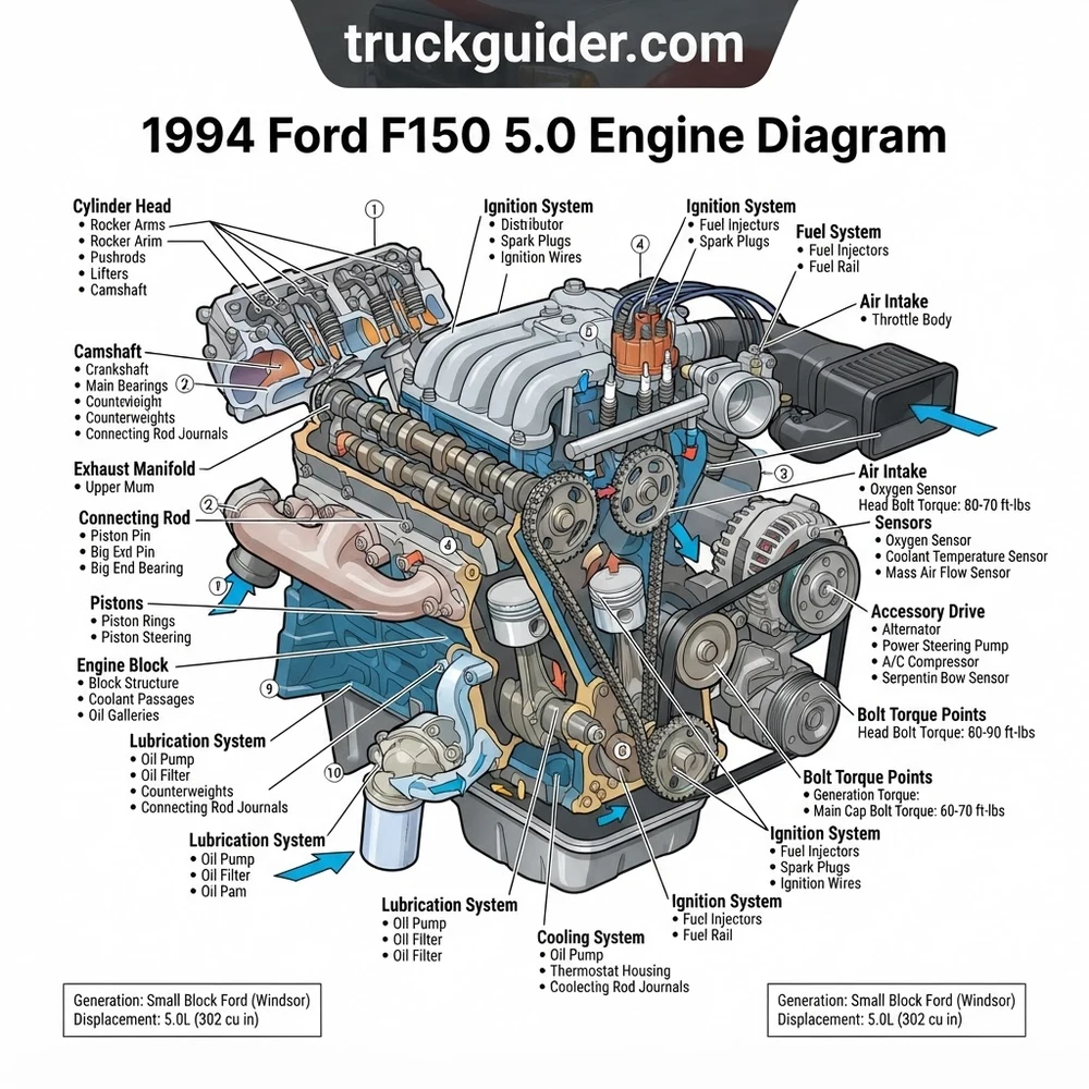
1994 Ford F150 5.0 Engine Diagram: Core Components Labeled
Recommended Best Deal Products


When analyzing a comprehensive 1994 Ford F150 5.0 engine diagram, the physical architecture splits into two primary zones: the induction and fuel management superstructure, and the rotating sub-assembly within the cast-iron foundation. The Ford 5.0L Windsor EFI V8 engine features an overhead-valve (OHV) pushrod configuration with a 4.000-inch cylinder bore and a 3.000-inch crankshaft stroke, yielding a precise displacement of 4,942 cc (301.6 cid).
At the top of the assembly sits the cast-aluminum upper intake manifold plenum, characterized by its long-runner design optimized for low-end torque production between 1,800 and 3,200 RPM. The upper plenum mates to a dual-bore 56 mm throttle body equipped with a Throttle Position Sensor (TPS) and an Idle Air Control (IAC) solenoid bypass valve. Directly below lies the cast-aluminum lower intake manifold, which functions as both an air runner path and a coolant distribution crossover. The lower manifold houses the Air Charge Temperature (ACT) sensor (located in the runner for cylinder number 5), the Engine Coolant Temperature (ECT) sensor, and the single-wire temperature gauge sending unit positioned on the forward driver-side water jacket passage.
The Electronic Fuel Injection (EFI) assembly operates as a multi-port, batch-fire (or sequential on California-spec MAF trucks) configuration. A stamped steel fuel rail anchors eight Bosch-style top-feed injectors rated at 19 lb/hr (identified by factory orange composite tops). Fuel pressure is managed by a manifold vacuum-referenced diaphragm regulator mounted on the return side of the rail, featuring a Schrader diagnostic service port configured to accept a standard 1/4-inch SAE mechanical fuel pressure gauge.
OEM Ford 5.0L Lower Intake Manifold Torque Spec: Step 1: 8 lb-ft (11 Nm); Step 2: 15 lb-ft (20 Nm); Final Step: 23-25 lb-ft (31-34 Nm). Torque bolts in a circular crisscross pattern starting from the center intake bolts outward toward the water jackets to prevent vacuum leaks and coolant contamination.
Underneath the intake runners, the structural foundation comprises high-strength cast-iron cylinder heads bolted directly to the heavy-duty engine block using 7/16-inch Grade 8 head bolts. The valve train relies on stamped steel 1.6:1 ratio pedestal-mount rocker arms anchored by 5/16-inch bolts torqued directly into the cylinder head castings. These transfer motion from 5/16-inch hardened steel pushrods down to factory hydraulic roller lifters guided by stamped steel dog-bone retainers and an internal spider hold-down tray secured within the lifter valley.
Within the cylinder bores, flat-top cast aluminum hypereutectic pistons with dual valve reliefs connect to forged I-beam steel connecting rods using floating wrist pins secured by press-fit small-end rod bushings. These connecting rods clamp down on the micro-polished journals of a nodular cast-iron crankshaft supported by a two-bolt main bearing architecture. The bottom end is fully sealed by a multi-bolt stamped steel oil pan containing a submerged gerotor oil pump driven by a hardened intermediate hex shaft from the base of the distributor.
1994 F-150 5.0 Vacuum Line Routing and Serpentine Belt Schematics

Tracing the vacuum infrastructure and front-end accessory drive (FEAD) requires consulting the factory under-hood schematics. The 1994 F-150 5.0L utilizes a single serpentine accessory drive assembly powered by a 6-groove micro-V drive belt routed across an automatic spring-loaded mechanical tensioner. The system drives a reverse-rotation water pump (featuring a smooth, ungrooved pulley turned by the backside of the belt), an internally regulated 3G alternator, an aluminum-body power steering pump, a scroll-type A/C compressor, and a secondary Thermactor (smog) air pump.
The vacuum routing system on the 1994 model year is notorious for degradation. Ford transitioned away from reinforced rubber lines to color-coded, semi-rigid nylon tubing that becomes exceptionally brittle under sustained thermal cycling. System vacuum originates at the upper intake manifold vacuum distribution tree, which features multiple barbed ports calibrated for specific mechanical systems.
| Vacuum Line Color | Source Location | Destination Component | Functional System |
|---|---|---|---|
| Red | Intake Manifold Tree | Fuel Pressure Regulator & Solenoid Bank | Manifold Vacuum Reference |
| Green | EVR Solenoid Output | EGR Valve Diaphragm | Exhaust Gas Recirculation |
| White | HVAC Selector Switch | Fresh/Recirc Air Door Actuator | Cabin Climate Control |
| Yellow / Pink | TAB / TAD Solenoid Valves | Thermactor Air Diverter/Bypass Valves | Secondary Air Injection |
| Black | Intake Manifold Tree | Vacuum Reservoir Tank (“Juice Can”) | System Supply Storage |
The vacuum solenoid tree is mounted on a stamped metal bracket beside the ignition coil on the forward driver-side cylinder head. It contains three critical electro-pneumatic valves: the EGR Vacuum Regulator (EVR), the Thermactor Air Bypass (TAB), and the Thermactor Air Diverter (TAD). These solenoids receive 12-volt battery power continuously, while the Ford EEC-IV Engine Control Unit pulses the ground circuits to bleed or apply vacuum to downstream actuators. The black steel reservoir canister (mounted low on the passenger wheel well) stores vacuum to prevent HVAC blending doors from dropping into default defrost mode during sustained wide-open-throttle operations.
For complete compliance and baseline troubleshooting, mechanics must match line runs to the OEM Vehicle Emission Control Information (VECI) decal positioned on the radiator support panel. If the VECI label is missing or damaged, trace the Thermactor plumbing directly from the smog pump outlet through the check valves to the rear cylinder head crossover pipe to confirm unmetered air is not entering the exhaust stream before the oxygen sensor.
Distributor Wiring, Roller Camshaft, and Firing Order Specs
Recommended Best Deal Products


Setting up the secondary ignition circuit on the 1994 5.0L Windsor requires strict adherence to revised OEM tolerances. While older 302 cubic inch V8 engines (pre-1994 truck models) utilized the classic 1-5-4-2-6-3-7-8 firing sequence, the 1994 F-150 5.0L features a revised hydraulic roller camshaft that shares the identical firing order of the 351W (5.8L) and the Mustang 5.0L HO: 1-3-7-2-6-5-4-8. The distributor rotor turns counterclockwise inside the distributor cap.
Do not wire a 1994 truck 5.0L using the legacy 302 firing order. The factory roller camshaft grind changes valve timing sequences entirely. Wiring the engine to the pre-1994 truck firing order will cause severe backfiring, unburnt fuel loading in the catalytic converter, and potential intake manifold backfire damage.
- Locate Top Dead Center (TDC): Manually rotate the crankshaft clockwise via the 15/16-inch harmonic balancer center bolt until the piston in Cylinder #1 (front cylinder on the passenger side) reaches absolute TDC on the compression stroke. Verify that the timing pointer aligns directly with the “0” mark on the outer ring of the harmonic balancer damper.
- Position and Seat the Distributor: Align the distributor housing so the Hall-effect Profile Ignition Pickup (PIP) internal sensor wiring harness points toward the front-left quadrant of the engine bay. Drop the distributor gear onto the camshaft drive gear, ensuring the internal oil pump driveshaft engages cleanly with the distributor shaft base. When fully seated flush against the engine block, the rotor tip must point precisely at the index notch cast into the distributor body lip corresponding to Cylinder #1.
- Route Secondary Spark Plug Leads: Install the distributor cap and route 8 mm suppression core wires in the exact counterclockwise sequence: 1-3-7-2-6-5-4-8. Cylinders are numbered 1-2-3-4 from front to rear on the passenger side, and 5-6-7-8 from front to rear on the driver side. Utilize factory plastic separators to keep plug wires 7 and 8 strictly isolated from one another along the driver-side valve cover; running wires 7 and 8 parallel in close proximity causes electromagnetic cross-induction, resulting in cylinder pre-ignition.
- Disconnect the SPOUT Shorting Bar: Before attempting to set ignition base timing with an inductive timing light, you must physically remove the Spark Output (SPOUT) shorting plug. On the 1994 model year, this is an inline two-wire push-in connector housing a grey plastic shorting bar, located taped within the wiring harness near the driver-side inner fender apron adjacent to the remote TFI module. Disconnecting the SPOUT disables the computer’s electronic dynamic spark advance curve.
- Lock Base Timing: Start the engine and bring it to full operating temperature (closed-loop coolant threshold above 160°F). Connect a timing light inductive clamp to spark wire #1. Loosen the 1/2-inch distributor hold-down clamp bolt using a distributor wrench. Slowly rotate the distributor housing until the pointer aligns precisely with 10° Before Top Dead Center (BTDC). Torque the hold-down bolt to 17-25 lb-ft (23-34 Nm), recheck the timing pointer, and reinsert the SPOUT connector to verify that the EEC-IV ECU immediately advances timing dynamically to roughly 20°-24° BTDC at curb idle.
A critical divergence on the 1994 5.0L platform involves the Thick Film Ignition (TFI) architecture. Unlike 1987-1992 models that bolted a grey push-start TFI module directly to the distributor bowl, the 1994 system features a remote-mounted black computer-controlled dwell (CCD) TFI module heatsinked to the driver-side metal inner fender well. Interchanging the black CCD module with an older grey push-start module leads to incorrect coil charging saturation, diagnostic trouble codes, and severe ignition breakdown under load.
1994 Ford F150 5.0 Engine Diagram Architectural Comparison
The 1994 production year represented an engineering intersection across the OBS Ford truck line. While passenger cars like the Mustang were transitioning away from the Fox-body layout, Ford trucks maintained dedicated platform characteristics while borrowing select performance enhancements. The following technical comparison establishes specific dimensional, electrical, and mechanical differences across contemporary Windsor architectures.
| Engine Metric | 1994 F-150 5.0L (302) | 1987-1993 F-150 5.0L | 1994 F-150 5.8L (351W) | 1994 Mustang 5.0L HO |
|---|---|---|---|---|
| Deck Height | 8.206 inches | 8.206 inches | 9.503 inches | 8.206 inches |
| Camshaft Type | Hydraulic Roller | Hydraulic Flat Tappet | Hydraulic Roller (F4TE) | Hydraulic Roller |
| Firing Order | 1-3-7-2-6-5-4-8 | 1-5-4-2-6-3-7-8 | 1-3-7-2-6-5-4-8 | 1-3-7-2-6-5-4-8 |
| Air Metering | MAP (SD) or MAF (CA) | Speed Density (MAP) | Speed Density (MAP) | Mass Air Flow (MAF) |
| TFI Module System | Remote Fender (Black CCD) | Distributor Mounted (Grey) | Remote Fender (Black CCD) | Remote Fender (Black CCD) |
| Intake Configuration | Dual-Runner Truck Upper | Dual-Runner Truck Upper | Dual-Runner Truck Upper | Low-Profile SN95 Upper |
Identifying the induction setup is critical for powertrain diagnosis. Most federal-emissions 1994 F-150 trucks utilize a Manifold Absolute Pressure (MAP) sensor mounted high on the firewall near the wiper motor, plumbed via a dedicated manifold vacuum line. California-emissions trucks, and select automatic models paired with the 4R70W transmission, were upgraded to sequential fuel injection governed by an inline 70 mm Mass Air Flow (MAF) meter clamped between the remote airbox and dual intake air tube assembly. Mechanics must consult the Ford EEC-IV diagnostic trouble codes to interpret engine management feedback accurately, as MAP and MAF calibrations use distinct fuel trim algorithms.
Common 302 Windsor Failure Points from Cylinder Heads to Oil Pan
Recommended Best Deal Products


Despite the robust reputation of the cast-iron small-block architecture, specific mechanical failures consistently develop on the 1994 5.0L Windsor assembly as operating hours accumulate. Pinpointing these issues on the engine diagram accelerates diagnostic workflows.
When replacing lower intake manifold gaskets on a 5.0L Windsor, permanently discard the composite or cork end-rail “china wall” gaskets supplied in aftermarket kits. Lay down a continuous 5/16-inch bead of high-temperature RTV silicone (such as Permatex Ultra Black or Motorcraft TA-31) along both the front and rear engine block rails, overlapping the cylinder head mating corners by 1/4 inch. Allow 15 minutes of skin-over time before torquing the manifold to prevent ongoing external oil leaks.
Lower Intake Gasket Deterioration
The interface between the aluminum lower intake manifold and cast-iron cylinder heads represents the most prevalent cooling system failure point. The factory composition gaskets deteriorate around the front and rear rectangular coolant crossover ports. When the seal degrades, pressurized coolant seeps into the lifter valley, contaminating the engine oil with ethylene glycol and destroying connecting rod bearings and main journals on the crankshaft. Alternatively, it leaks externally down the timing cover seam or pools at the rear of the block, often misdiagnosed as a leaking valve cover gasket or rear main seal.
Hall-Effect PIP Stator Failure
Within the distributor assembly, the Profile Ignition Pickup (PIP) sensor serves as the primary engine speed and crankshaft position sensor for the EEC-IV computer. Exposure to thermal soaking within the distributor base causes the micro-circuitry of this Hall-effect pickup to break open internally. The hallmark symptom is an intermittent hard stall or a crank-no-start condition that occurs only after the engine reaches normal operating temperature, returning to full functionality once the distributor cools down. Verifying PIP breakdown requires hooking a digital multimeter or LED test light to terminal 6 of the diagnostic data link connector to monitor the PIP switching signal (0V to 12V pulse) during extended cranking.
Harmonic Balancer Elastomer Separation
The factory two-piece external balance harmonic damper relies on an internal vulcanized rubber ring that bonds the heavy cast-iron inertia outer ring to the inner hub keyed to the snout of the crankshaft. Under sustained exposure to oil leaks and rotational torque, this elastomer fails. The outer ring slowly slips circumferentially relative to the inner hub. This mechanical displacement does not immediately cause severe vibration, but it renders the timing indicator markings on the outer rim inaccurate. If base timing reads 30° BTDC with the engine idling normally, the balancer ring has slipped, necessitating immediate balancer replacement before total outer-ring detachment damages the radiator or front accessory brackets.
Oil Pan and Rear Main Seal Seepage
The 1994 5.0L utilizes a one-piece Viton rear main crankshaft seal seated within a machined bolt-on aluminum retainer plate, a marked improvement over earlier multi-piece rope seals. However, oil starvation often occurs due to hardening of the multi-piece oil pan gasket over time. High-mileage trucks develop chronic leaks along the low-hanging sump rails. Replacing this gasket requires either raising the engine block several inches off its motor mounts or dropping the front axle crossmember assembly, as the internal oil pickup tube sits low against the bottom baffled pan floor.
For cross-platform drivetrain diagnostics, consult our related reference manuals, including the Ford E4OD transmission wiring diagram, the detailed Ford 5.8L 351W firing order schematic, and the specialized remote TFI module relocation guide to maintain complete electronic control over your truck’s ignition network.
1994 Ford F150 5.0 Engine Diagram Diagnostic Solutions
How can I verify if my 1994 F-150 5.0L uses Speed Density or Mass Air Flow?
Inspect the air intake ducting running between the driver-side fender air cleaner box and the dual-bore throttle body. If the intake configuration uses dual flexible rubber air tubes running uninterrupted from a split plastic air filter housing straight into the throttle body, the truck utilizes a Speed Density system governed by a firewall-mounted MAP sensor. If the air filter box exits through a single circular aluminum housing fitted with an internal sensor wire mesh and a four-pin electrical pigtail before splitting into dual tubes, the truck is equipped with a factory Mass Air Flow (MAF) system.
Why does my 1994 5.0L engine run rough if wired to the standard 302 firing order?
Ford phased in the F4TE-grind hydraulic roller camshaft across light-truck 5.0L production for the 1994 model year. This roller camshaft uses modified intake and exhaust lobe separation angles and timing sequences identical to the high-performance 351 Windsor marine and truck engines. If you wire the spark plug leads to the legacy 302 firing order (1-5-4-2-6-3-7-8), four out of the eight cylinders will ignite while the intake or exhaust valves are partially unseated, producing extreme rough running, severe intake backfiring, and unburnt fuel surging into the exhaust headers.
What is the correct diagnostic procedure to test for a failed remote TFI module?
When encountering a no-spark condition, confirm 12V+ power at the ignition coil positive terminal with the key in the “RUN” position. Next, probe pin 2 (PIP in) on the black fender-mounted remote TFI module using a digital logic probe or multi-meter set to Hertz (Hz). While an assistant cranks the engine, observe whether the PIP sensor sends an alternating square wave signal (approximately 20-30 Hz at cranking speed) from the distributor. If the PIP signal is present at the module harness but the TFI module fails to switch the ignition coil negative wire (pin 1, TACH circuit) to ground, the TFI module has sustained internal circuit breakdown and must be replaced.
Where is the SPOUT connector physically located on the 1994 F-150?
On the 1994 F-150 5.0L, the Spark Output (SPOUT) shorting bar connector is located on the driver-side inner fender apron, roughly 4 to 8 inches away from the black remote TFI module heatsink assembly. It appears as an unmounted, loose two-wire harness connector containing a removable grey plastic jumper plug. You must pull this jumper out before using a timing light on the crankshaft damper; leaving it connected will allow the EEC-IV engine computer to inject dynamic electronic timing advance, completely falsifying your base mechanical timing readings.
Step-by-Step Guide to Understanding the 1994 Ford F150 5.0 Engine Diagram
Identify – Verify the engine casting number above the starter pocket (F4TE indicates the 1994 roller-cam block).
Locate – Find cylinder #1 at the front passenger side to establish timing marks and distributor wire orientation.
Reference – Match diagram layout markers to cylinder head bolt locations, rocker arm pedestals, and intake manifold runners.
Connect/Route – Route spark plug wires following firing order 1-3-7-2-6-5-4-8, separating wires #7 and #8 to avoid crossfire.
Torque – Fasten cylinder head bolts in progressive stages: 55 lb-ft, 65 lb-ft, and a final pass at 70 lb-ft.
Verify – Pull the SPOUT connector, connect a timing light to plug wire #1, and calibrate base timing to 10° BTDC.
1994 Ford f150 5.0 Engine Diagram: Frequently Asked Questions
What generation is the 1994 ford f150 5.0 engine diagram?
The diagram corresponds to the ninth-generation Ford F-Series (OBS or Old Body Style), manufactured between 1992 and 1996. The 1994 model year introduced the factory roller camshaft block casting, transitioning away from earlier flat-tappet configurations while retaining the electronic multi-port fuel-injected EEC-IV engine management platform.
What are the main components visible in 1994 ford f150 5.0 engine diagram?
The diagram displays the cast-iron cylinder block, dual cylinder head assemblies, pushrod valve train, and bottom-end assembly including the cast-iron crankshaft and connecting rod sets. Ancillary equipment includes the upper and lower aluminum intake manifolds, remote ignition distributor, water pump, and serpentine belt-driven front accessory drive.
What are common failure points in 1994 ford f150 5.0 engine diagram?
Common failure points include cracked exhaust manifolds, worn timing chain slack, upper intake plenum vacuum leaks, and TFI ignition module heat soak. Internally, neglected oil service causes premature pushrod and hydraulic lifter ticking, while lower intake manifold gasket deterioration frequently allows coolant seepage into lifter valley oil passages.
What is the displacement of 1994 ford f150 5.0 engine diagram?
The engine has an exact displacement of 4,942 cc (301.6 cubic inches), colloquially marketed as a 5.0-liter 302 Windsor V8. It features a bore diameter of 4.000 inches (101.6 mm) and a stroke length of 3.000 inches (76.2 mm) with an 8.8:1 static compression ratio.
How do I identify 1994 ford f150 5.0 engine diagram year by VIN?
Locate the 17-digit vehicle identification number on the driver-side dashboard or door tag. The eighth digit represents engine displacement, designated as ‘N’ for the 5.0L V8. The tenth digit denotes the model year, where the letter ‘R’ specifically confirms the vehicle was produced for the 1994 model year.
What vehicles use 1994 ford f150 5.0 engine diagram?
This small-block Windsor engine layout applies to 1994–1996 Ford F-150, F-250, and full-size Bronco models. Variations of this 5.0L platform also appear across contemporary Ford E-150 Econoline vans, although truck versions utilize truck-specific cast intake manifolds designed specifically for broader low-end torque output curves.