1994 Ford Ranger Brake Line Diagram: Proper Routing (2026)

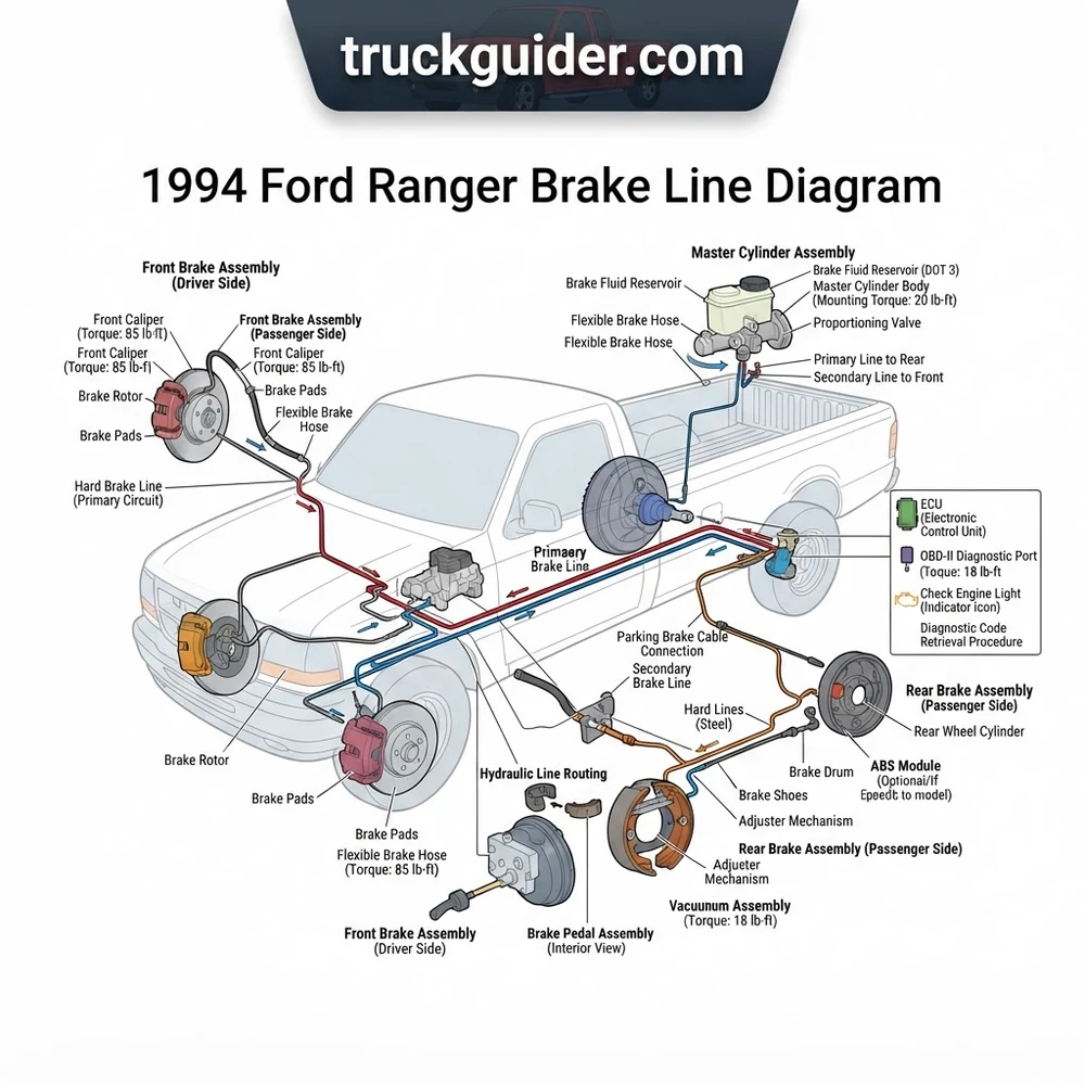
The 1994 Ford Ranger brake line layout routes 3/16-inch steel lines from the dual-reservoir master cylinder down the driver-side frame rail. The front port feeds the rear hydraulic circuit via the frame-mounted RABS hydraulic valve to a differential T-fitting, while the rear port supplies the front left and right calipers.
📌 Key Takeaways
- Uses 3/16-inch standard steel lines with 3/8-24 inverted flare tube nuts throughout the hydraulic chassis.
- Primary split routes front port to Rear Anti-Lock Brakes (RABS) valve and rear port to front calipers.
- Critical bleeder screw torque spec is 80-108 in-lbs; line fittings require 10-14 lb-ft to avoid stripping.
- Severe corrosion along the driver-side inner frame rail near the fuel filter is the top failure point.
- Replace damaged rigid lines yourself, but seek professional service if the RABS valve or ECU triggers a fault.
The 1994 Ford Ranger utilizes a split hydraulic braking circuit paired with a single-channel Rear Anti-Lock Brake System (RABS II). Whether you are overhauling corroded factory tubing or chasing an unresponsive pedal, consulting an accurate 1994 Ford Ranger brake line diagram is essential for tracing factory routing, port thread dimensions, flare styles, and intermediate hydraulic valving. The second-generation Ranger routes high-pressure fluid from a dual-reservoir master cylinder down the driver-side frame rail, passing through an electronic hydraulic valve before feeding front disc calipers and rear drum wheel cylinders. This technical article details the physical routing, fitting specifications, failure diagnostics, torque values, and manual bleeding sequences required for professional brake system restoration.
1994 Ford Ranger Brake Line Diagram: Layout and Physical Routing
Recommended Best Deal Products


The hydraulic layout on the 1994 Ford Ranger splits fluid delivery into two discrete hydraulic circuits: a primary front system that manages the driver and passenger dual-piston or single-piston sliding calipers (depending on chassis GVWR and 2WD versus 4WD configuration) and a secondary rear circuit operating the duo-servo rear drum assemblies. Tracing the lines requires understanding how the frame channel protects and guides each run.
Master Cylinder and Proportioning Valve Circuitry

The aluminum master cylinder mounts to the vacuum brake booster on the driver-side firewall. It features an offset dual-chamber reservoir filled with DOT 3 hydraulic fluid. The forward port supplies hydraulic pressure to the front brake circuit, while the rearward port (closest to the booster) feeds the rear circuit. Unlike later integrated ABS hydraulic control units, the 1994 chassis positions an inline residual or proportioning valve assembly immediately below or integrated into the lower master cylinder outlet ports, maintaining line pressure balance before routing lines toward the lower chassis.
Front Hard Line Split and Engine Crossmember Routing
From the master cylinder, the front circuit hard line descends along the inner driver-side fender apron down to a junction block mounted on the top lip of the frame rail. At this junction, the front circuit divides:
- Driver-Side Caliper Feed: A short 3/16-inch steel hard line routes forward along the upper driver frame rail, terminating at a frame bracket that couples to a flexible rubber hose leading directly to the front-left brake caliper.
- Passenger-Side Caliper Feed: A preformed 3/16-inch steel hard line drops into the engine crossmember pocket beneath the oil pan. It tracks securely inside the channel alongside steering links, routed safely away from the engine oil pressure sending unit and lower radiator coolant flow pipes to prevent radiant thermal breakdown of the fluid. The line emerges on the inner passenger frame rail, terminating at a symmetrical frame mounting tab where it joins the flexible hose for the front-right caliper.
Rear Anti-Lock Brake System (RABS II) Valve and Axle Drop
The secondary line exits the master cylinder and routes downward to the inlet port of the RABS II hydraulic control valve, secured inside the driver frame rail webbing directly below the steering shaft. Inside this valve, a computer-controlled dump solenoid and accumulator modulate line pressure during rear-wheel lockup events.
A single 3/16-inch hard line leaves the RABS valve outlet and travels rearward along the inside of the C-channel driver-side frame rail. It navigates past the transmission crossmember, fuel filter bracket, and the plastic fuel tank assembly. Above the rear differential housing, the hard line terminates at a heavy-gauge frame bracket. Here, it connects to a flexible rubber center drop hose. The lower end of this drop hose incorporates an integral brass distribution block secured directly to the rear axle housing via a hollow axle breather vent bolt. From this tee, two rigid 3/16-inch steel lines trace the axle tubes outward to the left and right rear wheel cylinders.
Brake Line Sizes, Flare Specs, and Torque Spec Reference
Fabricating replacement lines for a 1994 Ranger requires strict adherence to OEM flare geometry and thread pitches. Ford utilized both standard SAE threads and metric fittings on this chassis. Using an incorrect flare type or cross-threading unmatched fittings will ruin replacement components and induce high-pressure fluid leaks.
| Line Section / Location | Tubing Outer Diameter | Thread Pitch & Fitting Spec | Flare Geometry |
|---|---|---|---|
| Master Cylinder Front Port (Primary) | 3/16 in. (4.75 mm) | 3/8-24 Inverted Flare Tube Nut | SAE 45° Inverted Double Flare |
| Master Cylinder Rear Port (Secondary) | 3/16 in. (4.75 mm) | 7/16-24 or 1/2-20 Special Thread | SAE 45° Inverted Double Flare |
| RABS II Valve Inlet Port | 3/16 in. (4.75 mm) | 7/16-24 Inverted Tube Nut | SAE 45° Inverted Double Flare |
| RABS II Valve Outlet Port | 3/16 in. (4.75 mm) | 3/8-24 Inverted Tube Nut | SAE 45° Inverted Double Flare |
| Intermediate Rear Hard Line Union | 3/16 in. (4.75 mm) | 3/8-24 Female-to-Female Union | SAE 45° Inverted Double Flare |
| Front Caliper Inlets (Banjo Bolt) | Rubber Flex Line ID | 3/8-24 or M10x1.5 Banjo Bolt | Crush Washer Copper Face Seal |
| Rear Wheel Cylinder Inlets | 3/16 in. (4.75 mm) | 3/8-24 Inverted Tube Nut | SAE 45° Inverted Double Flare |
When replacing rusted sections, select copper-nickel alloy tubing (NiCopp / UNS C70600) conforming to SAE J1047 standards. NiCopp provides superior corrosion resistance against road salts, bends cleanly without kinking along tight frame pockets, and seals reliably when flared to an SAE 45-degree inverted double flare. Avoid using ISO bubble flare tooling on this chassis; inverted double flares are mandatory across the factory union blocks, RABS module, and wheel cylinder ports.
Master cylinder outlet tube nuts: 10–15 lb-ft (14–20 Nm)
RABS module inlet/outlet flare nuts: 12–17 lb-ft (16–23 Nm)
Axle tube wheel cylinder flare nuts: 10–14 lb-ft (14–19 Nm)
Front caliper flex hose banjo bolt torque spec: 20–30 lb-ft (27–41 Nm)
Axle housing vent bolt (junction tee mount): 12–18 lb-ft (16–24 Nm)
1994 Ford Ranger Brake Line Diagram Failure Points and Wear Zones
Recommended Best Deal Products


Second-generation Ford Rangers (model years 1993–1997) exhibit distinct structural zones where road salt, vibration, and road grime induce premature hydraulic degradation. Technicians must concentrate inspections on three primary failure zones along the chassis rail.
The Fuel Tank Corrosion Trap on the Driver Frame Rail
The single most catastrophic failure point on the 1994 Ranger is the rear main hard line where it runs behind the steel or plastic fuel tank. The factory routing clips hold the 3/16-inch steel line tightly against the inner frame rail flange. Over time, moist road debris, gravel, and winter brine pack between the fuel tank strap bracket and the frame rail, completely encasing the brake line. Because this area cannot be easily rinsed during routine vehicle washing, the protective zinc coating on OEM steel tubing blisters away. Pinholes typically develop here without warning, resulting in immediate pressure drop and fluid discharge when the driver applies heavy pedal force.
RABS II Dump Valve Hydraulic Bypassing
The frame-mounted RABS II valve is vulnerable to moisture contamination inside old brake fluid. As water settles into the lower valve body, internal corrosion seizes the spring-loaded hydraulic dump piston. When this occurs, hydraulic fluid intended for the rear drums bypasses back into the internal accumulator chamber under hard braking. The driver experiences a progressively sinking pedal that mimics an internal master cylinder cup seal failure. Unlike an electrical fault that activates the instrument cluster yellow “REAR ABS” warning lamp, mechanical valve leakage often leaves the system without a registered diagnostic trouble code.
Flexible Axle Drop and Front Caliper Hose Deterioration
Rubber flexible brake lines suffer both external dry rot and internal laminate breakdown. The rear center drop hose constantly flexes with axle articulation over road irregularities. Cracking appears around the metal crimp sleeves where road debris strikes the suspension. Internally, deteriorating rubber flaps can act as one-way check valves, retaining pressure within the rear wheel cylinders and causing severe drum drag, excessive heat, and ruined shoes. Similar degradation occurs at the front wheels, where tight turns stress the front flexible caliper drops.
Escaping brake fluid under hydraulic line pressure (exceeding 1,000 PSI) can penetrate skin tissue. Never use bare hands to trace suspected pinhole leaks while an assistant applies pedal pressure. Furthermore, glycol-based DOT 3 brake fluid rapidly strips automotive paint, enamel chassis coatings, and corrodes unsealed engine sensor harnesses.
Diagnosing Hydraulic Leaks on a 1994 Ford Ranger Step by Step
Isolating hydraulic pressure drops on the second-generation Ranger requires a methodological approach to differentiate mechanical hard-line ruptures from internal component failure. Follow this field-tested procedure to identify leaks and verify system integrity.
- Static Master Cylinder Reservoir and Level Inspection: Clean the exterior reservoir cap to prevent contamination. Remove the diaphragm cap and observe fluid levels across both chambers. If the forward chamber is depleted, the leak resides within the front caliper circuits or crossmember piping. If the rear chamber is empty, focus your search on the RABS valve, the main rear frame line, or the drum wheel cylinders. Top off with clean DOT 3 fluid.
- Engine-Off Hydraulic Pressure Decay Test: With the ignition switched off, pump the brake pedal 5 to 6 times to exhaust all residual vacuum assist from the brake booster. Press firmly on the brake pedal with approximately 50 to 70 pounds of force and hold for 30 seconds. A firm pedal that holds height indicates a sealed hydraulic circuit. If the pedal slowly drops toward the floorboards without visible exterior dripping, an internal bypass exists at the master cylinder piston seals or the RABS II dump valve.
- RABS Module Diagnostic Code Interrogation: If an electronic or hydraulic anomaly triggers the amber RABS dash warning lamp, access the diagnostic connector beneath the driver-side dashboard near the parking brake mechanism. Grounding the black/orange tracer wire while the ignition key is on causes the dashboard light to flash diagnostic codes (such as Code 4 indicating a grounded RABS valve switch, or Code 9 indicating high sensor resistance). Note that this system operates independently of the EEC-IV engine ECU; an OBD-II code reader cannot communicate with this early anti-lock circuit, and the check engine light does not flash brake codes.
- Under-Chassis Pressure Leak Tracing: Elevate the truck on four safety stands. Have an assistant depress the brake pedal firmly while you trace the entire length of the hydraulic circuit with a high-intensity inspection light. Visually inspect:
- Master cylinder port seals and lower firewall booster interface.
- RABS valve bleeder screw, end plug, and electrical harness connector.
- The concealed run behind the frame-mounted fuel tank.
- The crossmember line beneath the engine, inspecting for wear spots near steering shafts and engine oil pressure lines.
- Wheel Cylinder and Caliper Seal Examination: Pull back the rubber dust boots on the front sliding calipers to check for fluid migration past the piston square-cut seals. On the rear axle, remove both brake drums. Gently pry back the outer rubber dust boots on the left and right wheel cylinders with a small pocket screwdriver. If wet DOT 3 fluid leaks out, the internal cup seals have failed, necessitating cylinder replacement.
1994 Ford Ranger Brake Line Bleeding Order and RABS Torque Specs
Recommended Best Deal Products


Bleeding a 1994 Ford Ranger equipped with RABS II differs significantly from bleeding standard non-ABS trucks. Air easily traps inside the downward-facing cavities of the RABS valve assembly. If the valve is not bled in its correct sequence, entrained air will cause a spongy pedal regardless of how much fluid is drawn through the wheel cylinders.
Always purge the RABS hydraulic valve bleeder screw prior to bleeding the rear drum wheel cylinders whenever the main hard line has been disconnected, drained, or replaced. Attempting to force trapped air down through the entire frame line to the rear axle often aerates fluid downstream.
- Bench Bleed the Master Cylinder: If the master cylinder was drained or replaced, mount it securely in a bench vise. Route plastic bleed tubes from the forward and rear outlet ports back into the reservoir. Stroke the primary piston slowly using a smooth dowel until all air bubbles cease escaping into the fluid. Install port plugs, mount the unit onto the booster, and torque the retaining nuts to 18–25 lb-ft (24–34 Nm).
- Bleed the RABS II Hydraulic Valve: Locate the 5/16-inch or 8mm bleeder screw mounted directly on the RABS valve body on the inner driver frame rail. Attach a clear vinyl hose submerged in a clean jar of fresh fluid. Have an assistant depress the brake pedal smoothly, then open the RABS bleeder screw one-quarter turn. Close the screw before the pedal hits the floor. Repeat 3 to 5 times until bubble-free fluid flows. Tighten the RABS bleeder screw to 7–9 lb-ft (84–108 in-lb).
- Purge the Rear Right Wheel Cylinder: Move to the wheel cylinder furthest from the master cylinder (passenger-side rear). Clean the bleeder fitting. Open the bleeder, allow fluid expulsion under pedal pressure, and lock the screw before pedal release. Repeat until the discharge is clear and free of aeration. Torque the bleeder to 7–9 lb-ft (84–108 in-lb).
- Purge the Rear Left Wheel Cylinder: Repeat the bleeding sequence at the driver-side rear wheel cylinder, maintaining continuous fluid level checks at the master cylinder reservoir to prevent drawing in ambient air.
- Bleed the Front Right Brake Caliper: Move to the passenger-side front caliper. Attach the drain bottle, open the bleeder screw (typically 3/8-inch or 10mm), and execute the stroke-and-hold sequence until fluid is completely free of micro-bubbles. Torque bleeder screw to 8–11 lb-ft (11–15 Nm).
- Bleed the Front Left Brake Caliper: Finalize hydraulic bleeding at the driver-side front caliper closest to the master cylinder. Confirm that all four bleeder screws and the RABS valve bleeder are secured within factory torque limits.
- Final Circuit Verification: Depress the pedal with high effort while the engine runs to introduce booster vacuum. The pedal must settle high and firm with no spongy travel. Ensure no wet residue appears at any newly installed flare connections or distribution fittings.
1994 Ford Ranger Hydraulic Brake System FAQ
Can I bypass the RABS valve on a 1994 Ford Ranger if replacement parts are unavailable?
Technically, you can plumb the master cylinder rear output line directly into the rear main line using an inverted flare union (3/8-24 to 7/16-24 female fitting adapter). However, eliminating the RABS II valve disables anti-lock intervention and removes the factory brake proportioning balance. Under heavy or panic braking in an unladen truck bed, the rear drum brakes will lock prematurely, inducing vehicle spin. For legal compliance and road safety, sourcing an OEM or professionally rebuilt RABS II hydraulic control unit is strongly recommended over an unregulated line bypass.
Does a 1994 Ford Ranger require bubble flare or double flare brake lines?
The 1994 Ford Ranger relies almost exclusively on standard SAE 45-degree inverted double flares for its rigid brake lines. Unlike later European or contemporary domestic models that adopted ISO bubble flares or quick-connect push fittings, the second-generation Ranger uses standard American double-flaring across the junction blocks, flexible line brackets, rear axle tee, and wheel cylinders. Never mate an ISO bubble flare into an inverted flare seat; the mismatched mating geometry prevents proper seal face engagement and will leak under hydraulic pressure.
Why does my brake pedal sink to the floor even though no fluid is leaking externally?
A sinking pedal with a stable reservoir fluid level points to an internal hydraulic pressure bypass. On a 1994 Ranger, this problem typically stems from one of two components: worn internal piston cup seals in the master cylinder allowing high-pressure fluid to slip back into the low-pressure reservoir, or a malfunctioning RABS II valve dump solenoid. If the internal dump piston in the RABS unit fails to seat properly against its valve bore, fluid bypasses directly into the RABS accumulator chamber whenever you depress the brake pedal.
Will a brake line pressure loss trigger a check engine light or diagnostic code?
A loss of hydraulic brake pressure will not trigger the engine ECU or illuminate the check engine light. Engine management diagnostic parameters on the 1994 Ranger focus strictly on powertrain functions such as coolant flow sensors, fuel trim, ignition timing chains, and oil pressure monitoring. Instead, brake line pressure drop activates the red “BRAKE” warning lamp on the dashboard when the differential pressure switch inside the proportioning valve shifts off-center. An electrical fault in the anti-lock circuitry will illuminate the separate yellow “REAR ABS” lamp, which stores flash codes accessible only via the dedicated under-dash test connector.
What is the total brake fluid capacity required to completely flush a 1994 Ranger?
A standard dry-fill or complete system flush on a regular cab or SuperCab 1994 Ranger requires approximately 32 fluid ounces (one standard quart) of fresh, clean DOT 3 motor vehicle brake fluid from an unopened container. When performing extensive line replacements—especially replacing the long rear main hard line—purchase two 32-ounce containers to account for bench bleeding the master cylinder and continuous bench-to-caliper purging.
Step-by-Step Guide to Understanding the 1994 Ford Ranger Brake Line Diagram
Identify – Inspect master cylinder ports, labeling the front and rear brake hydraulic line feeds.
Locate – Find the RABS valve on the driver-side frame rail directly below the steering shaft.
Reference – Match the physical hard lines against the diagram to verify routing along chassis clips.
Connect/Route – Bend replacement 3/16-inch tubing to mirror factory contours and secure into frame brackets.
Torque – Tighten line flare fittings to 10-14 lb-ft torque spec using a dedicated flare nut wrench.
Verify – Bleed brakes sequentially starting right-rear, left-rear, right-front, to left-front; check for leaks under pedal load.