1994 Ford Ranger Fuse Box Diagram: Troubleshooting Repair (2026)

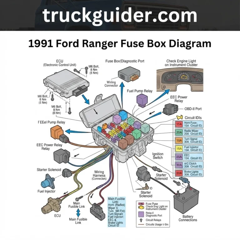
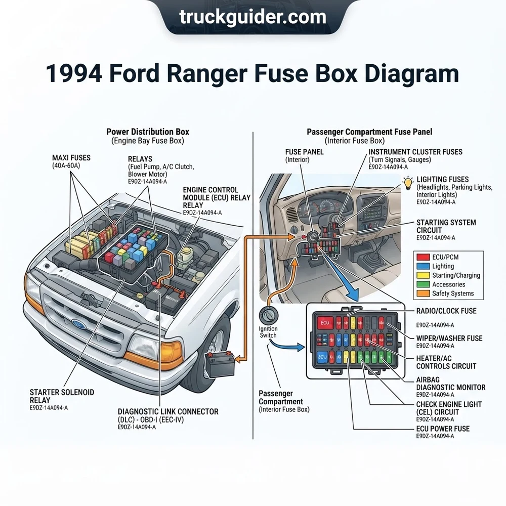
The 1994 Ford Ranger features an interior fuse panel located under the driver-side dashboard to the left of the steering column and an engine-bay Power Distribution Box near the air cleaner. Critical circuits include Fuse 13 (15A stop/hazards) and under-hood Maxi-Fuses (30A/60A) powering the ECU, fuel pump relay, and alternator circuits.
📌 Key Takeaways
- The interior panel houses standard ATO/ATC blade fuses (5A to 30A), while the engine compartment distribution box uses high-amp Maxi-fuses up to 60A.
- Interior Fuse 13 (15A) protects hazard flashers and brake switches; engine Fuse 1 (30A Maxi) delivers direct unswitched battery feed to the ECU.
- Always disconnect the negative battery cable before servicing engine bay Maxi-fuses, and torque battery terminal clamps to 60-80 lb-in.
- Corrosion or moisture intrusion in the under-hood distribution box frequently causes intermittent fuel pump relay dropouts and no-start conditions.
- Replace blown blade fuses independently, but consult a professional technician if an ECU circuit trips repeatedly or exhibits wiring harness melts.
Accurate electrical diagnosis on the second-generation 1994 Ford Ranger requires a complete understanding of its bifurcated circuit architecture. Before Ford adopted standardized OBD-II protocols across its light truck lineup in 1996, the 1994 model year relied on the proprietary Ford EEC-IV engine computer management system. This setup splits circuit protection between an in-cab instrument panel junction block and an under-hood high-current power distribution box. Whether you are troubleshooting an intermittent no-start condition, tracking down uncommanded voltage drops to the ECU, or resolving instrument cluster sensor anomalies, this technical guide and reference diagram break down the specific terminal assignments, fuse ratings, wire colors, and operational functions for the 1994 platform.
1994 Ford Ranger Fuse Box Diagram: In-Cab Panel Layout and Pinout
Recommended Best Deal Products


The interior passenger compartment fuse block serves as the secondary power distribution node for low-to-medium-current cabin accessories, interior and exterior lighting circuits, safety restraints, and gauge cluster inputs. In the 1994 Ford Ranger, this panel is mounted securely behind an access panel on the lower-left section of the driver-side dashboard, just below the headlamp pull switch and to the left of the steering column assembly. To access the panel, pull the lower lip of the plastic trim cover outward until the spring retaining clips disengage.
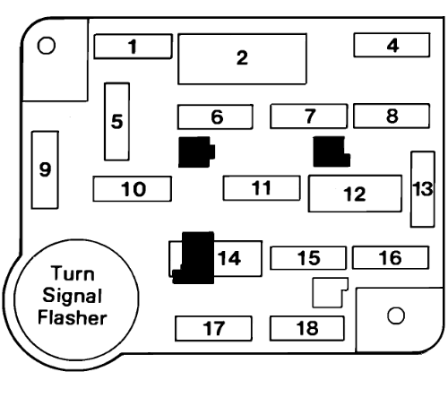
The interior panel exclusively utilizes standard ATO/ATC fast-acting automotive blade fuses. In addition to branch circuit protection, the interior panel houses the cylindrical, two-prong turn signal flasher unit on the lower-left face of the block, while the hazard warning flasher is positioned on the rear face of the fuse junction board. When addressing issues with the turn signals or emergency flashers, mechanics must verify power supply from the corresponding fuse before condemning the thermal flasher units.
This identical fuse block architecture and terminal pinout apply directly to the badge-engineered 1994 Mazda B-Series platform (specifically the B2300, B3000, and B4000). While trim components and body harness routing diverge slightly between Mazda and Ford assembly plants, the underlying fuse board layout, wire color codings, and operational amp ratings remain completely interchangeable between models.
| Fuse # | Amperage | Fuse Color | Wire Primary / Stripe | Protected Circuits and Functional Load |
|---|---|---|---|---|
| 1 | 15A | Light Blue | Light Blue / Red | Instrument panel illumination lamps, radio display dimmer, climate control panel lighting |
| 2 | — | — | — | Unassigned / Open cavity |
| 3 | 20A | Yellow | Light Green / Yellow | Turn signal flasher, back-up lamps, daytime running lights (DRL module on Canadian models) |
| 4 | 15A | Light Blue | Red / Black | Exterior park lamps, side marker lamps, tail lamps, license plate lamps |
| 5 | 10A | Red | Purple / Orange | Airbag Supplemental Restraint System (SRS) diagnostic module power |
| 6 | 15A | Light Blue | Dark Green / Orange | Rear anti-lock brake (RABS II) module, stop lamps, high-mount third brake lamp |
| 7 | 15A | Light Blue | Yellow / Black | Power accessory feed, power mirror switch, auxiliary power port relay coil |
| 8 | 30A | Light Green | Black / Orange | Heater-A/C blower motor speed resistor assembly and blower motor switch |
| 9 | 30A C.B. | Silver (Metal) | Light Blue / Black | Power windows master control switch, power door lock actuators |
| 10 | — | — | — | Unassigned / Open cavity |
| 11 | 15A | Light Blue | Light Blue / Pink | Electronic audio unit (Radio memory, keep-alive power, ignition hot input) |
| 12 | 10A | Red | Red / Yellow | Warning indicator lights, instrument cluster run bus, electronic 4×4 control module |
| 13 | 15A | Light Blue | Red / Light Green | Stop/hazard flasher, speedometer power, RABS module power keep-alive |
| 14 | — | — | — | Unassigned / Open cavity |
| 15 | — | — | — | Unassigned / Open cavity |
| 16 | 30A | Light Green | Black / White | Windshield wiper motor, washer pump motor, wiper interval governor |
| 17 | 10A | Red | White / Purple | Starter motor relay control coil circuit, clutch interlock switch (or park/neutral switch) |
| 18 | 15A | Light Blue | Light Blue / White | Cigar lighter socket, diagnostic link connector (Data Link 12V constant power) |
When tracking gauge fluctuations, examine Fuse 12. This circuit supplies regulated operational power to the instrument cluster logic board. If an internal short develops or resistance climbs within this line, cluster readings become skewed. For instance, you might see inaccurate data for the oil pressure gauge, or the coolant temperature gauge may fail to reflect real-time coolant flow across the thermostat housing.
Cavity 9 frequently uses a metal-cased cycling circuit breaker rated at 30 amps rather than a standard sacrificial fuse. If power windows draw excessive current due to mechanical binding in the window run channels, this breaker trips thermally, cuts circuit power, and resets automatically once cooled.
Under-Hood Power Distribution Box and ECU Relay Layout
The under-hood Engine Compartment Power Distribution Box handles primary battery feeds, high-amperage sub-circuits, and key engine management controls. This durable plastic enclosure sits on the driver-side inner fender apron, directly forward of the brake master cylinder and hydraulic booster assembly. Release the two plastic perimeter latches and lift the hinged cover to access the high-current Maxi fuses and ISO micro-relays inside.
This panel acts as the main hub connecting the 12-volt battery source, the high-output alternator charging circuit, and the powertrain operating harness. Unlike the ATO/ATC blade fuses inside the cab, the high-amp circuits here use high-interrupting-rating Maxi fuses ranging from 20A to 60A. These supply primary power down to the ignition switch, interior junction box buses, and inductive engine loads.
| Location ID | Component Type | Rating | Protected Circuit and Controlled Load |
|---|---|---|---|
| Maxi-Fuse 1 | Maxi Fuse | 50A (Red) | Primary ignition switch run/start circuits, in-cab fuse bus feeds |
| Maxi-Fuse 2 | Maxi Fuse | 60A (Blue) | Instrument panel fuse block battery constant bus (Fuses 4, 6, 8, 13) |
| Maxi-Fuse 3 | Maxi Fuse | 30A (Green) | EEC Power Relay main contact power, Ford EEC-IV Engine Computer |
| Maxi-Fuse 4 | Maxi Fuse | 20A (Yellow) | Fuel Pump Relay contact circuit, high-pressure in-tank electric pump |
| Maxi-Fuse 5 | Maxi Fuse | 40A (Orange) | Anti-Lock Brake System (ABS) hydraulic control unit pump motor |
| Maxi-Fuse 6 | Maxi Fuse | 30A (Green) | Headlamp switch, high-beam flasher, daytime running light interface |
| Relay 1 | ISO Micro-Relay | SPST / 12V | EEC Power Relay (switches battery power to ECU, injectors, and MAF) |
| Relay 2 | ISO Micro-Relay | SPST / 12V | Fuel Pump Relay (ground-controlled by ECU Pin 22) |
| Relay 3 | ISO Micro-Relay | SPST / 12V | A/C Wide-Open Throttle (WOT) Cut-Off Relay |
| Relay 4 | ISO Micro-Relay | SPST / 12V | Horn Relay (activated by steering wheel horn switch contacts) |
The operational interaction between Relay 1 (EEC Power Relay) and Relay 2 (Fuel Pump Relay) is critical for engine operation. When the ignition switch rotates to “RUN,” terminal 86 on the EEC Power Relay energizes, pulling down terminal 87. This instantly routes battery voltage directly to Pins 37 and 57 of the 60-pin EEC-IV engine computer.
Simultaneously, this action routes positive voltage to one side of the Fuel Pump Relay control coil. The engine computer then pulls pin 22 down to ground for approximately two seconds to prime the high-pressure fuel rail. It maintains this ground path continuously only after receiving a dynamic profile ignition pickup (PIP) profile pulse from the distributor (or crankshaft position sensor on distributorless engines). If the engine computer detects complete loss of crank synchronization, it drops the ground circuit to cut fuel delivery immediately.
The EEC-IV and Fuel Pump relays utilize standard ISO 5-pin mini footprint sockets. Specified coil resistance measures between 65 and 90 ohms at 68°F (20°C). When inspecting circuit integrity, the contact drop across terminal 30 to terminal 87 should not exceed 0.25 volts DC while operating under full circuit load.
1994 Ford Ranger Fuse Box Symptoms and Blown Circuit Causes
Recommended Best Deal Products


Electrical circuit faults on the 1994 Ranger generally present as component failures tied to specific circuit branches. Pinpointing the root mechanical or electrical cause requires matching the symptom to the vulnerable link in the harness:
- Engine Cranks Continuously but Won’t Fire (Check Engine Light Inoperative): If the check engine light fails to illuminate during key-on engine-off (KOEO) bulb check, the Ford EEC-IV Engine Computer is not powering up. This typically traces to a blown under-hood Maxi-Fuse 3 (30A) or internal contact oxidation within the EEC Power Relay. Without clean system voltage at pins 37 and 57, the computer cannot operate the ignition module, fire the fuel injectors, or provide power to sensors.
- Engine Cranks, Check Engine Light Illuminates, but Fuel Pressure Measures 0 PSI: If the cluster light passes its bulb test but the fuel pump won’t run, check under-hood Maxi-Fuse 4 (20A) and the Fuel Pump Relay. If those test good, inspect the Fuel Inertia Shut-off Switch located in the passenger cabin footwell, positioned forward of the carpet edge behind the transmission tunnel or kick trim. Mechanical shocks, severe chassis vibration, or harness deterioration can trip this safety switch, cutting power along the Pink/Black-stripe wire running to the fuel pump assembly.
- Dead Cabin Instruments and Inoperative Back-up Lamps: A sudden failure of the instrument cluster gauges—accompanied by non-functional reverse lights—points to a blown interior Fuse 3 (20A). A common source of this short is the back-up lamp switch harness mounted on the manual transmission tailhousing (or neutral-safety range switch on A4LD automatic transmissions). The harness can unclip, fall onto hot exhaust piping, and melt through to ground.
- Wipers Park Incorrectly or Function on High Speed Only: When the wiper motor operates erratically or blows Fuse 16 (30A), the wiper interval governor module mounted under the dashboard has often failed internally. Alternatively, the wiper linkage bushings may have seized, overloading the motor assembly and drawing more than the rated 30 amps.
- Total Charging Failure and In-Cab Dead Bus (Fusible Link Burnout): When Maxi-Fuse 1 and Maxi-Fuse 2 show zero voltage on all test tabs, inspect the high-current fusible links connected to the starter relay mounted on the passenger-side inner fender. Continuous excessive alternator draw, reverse-polarity battery jump starts, or short circuits in the primary harness can melt these calibrated wire links, opening battery-feed paths across the entire truck.
- Intermittent Sensor Readouts and Erroneous Warnings: In rare cases, a failing sensor may mimic fuse trouble. For example, severe mechanical timing chain slack on the Cologne 4.0L V6 can cause camshaft position fluctuation that looks like a diagnostic code power drop. Similarly, if oil pressure plunges due to pump cavitation, the dash gauge may flutter and look like an electrical short at Fuse 12. Cross-reference questionable electrical values using a mechanical gauge or an accurate diagnostic test port check.
Never bypass a blown fuse with high-amperage jumpers, foil, or incorrect wire. The factory harness gauges on the 1994 Ranger are sized precisely for their designated load limits. Over-fusing an ATO/ATC terminal can overheat the harness, melt the interior junction box backplane, and ignite underlying dash materials.
Steps to Test Fuses and Read EEC Diagnostic Trouble Codes
Diagnosing electrical problems on this platform requires a systematic approach. The diagnostic routine below moves from verifying fuse integrity to extracting on-board diagnostic trouble codes through the pre-OBD-II communication port.
- Perform In-Situ Voltage Drop Tests across Blade Fuses:
Set your high-impedance Digital Multimeter (DMM) to DC Volts on the 20V scale. Attach the negative multimeter test lead directly to clean chassis ground or the battery negative terminal post. Turn the truck’s ignition lock cylinder to the “RUN” position. Without removing the ATO/ATC blade fuses from the fuse box, touch the positive probe tip into each of the two exposed metallic test points on the top face of each fuse. A healthy circuit shows battery voltage (12.4V to 12.8V) at both test tabs. If one tab shows system voltage while the opposing tab reads 0.00V, the fuse element is blown. If both read 0.00V, that branch circuit is switched off or disconnected upstream. - Inspect Fusible Links at the Starter Relay:
Locate the primary starter relay mounted to the passenger-side inner fender apron. Trace the secondary gauge wires emerging from the primary battery cable terminal post. These wires incorporate calibrated fusible link segments wrapped in heat-resistant hypalon insulation. Grasp each link firmly and apply moderate pulling tension. If the wire stretches like soft rubber, the internal copper conductor has melted from an over-current condition, and the link must be cut out and replaced with an exact-gauge match. Make sure to review proper Ford Ranger starter relay wiring procedures before replacing any damaged links. Verify the terminal stud nuts are torqued to factory specifications:🔧 SpecificationTorque spec for the 5/16-24 copper primary studs on the fender-mounted starter relay is 70 to 95 in-lb (7.9 to 10.7 Nm). Do not over-torque, or you will fracture the internal bakelite base plate.
- Verify Under-Hood Power Distribution Voltages:
Remove the cover from the under-hood Engine Compartment Power Distribution Box. Measure the line-side input pins for the EEC Power Relay and Fuel Pump Relay at terminal 30 using your meter. Both pins must supply uninterrupted 12-volt battery power at all times. Turn the ignition key to the “RUN” position and confirm 12-volt switched power reaches terminal 86 of the EEC Power Relay. If power is missing at terminal 86, test the ignition switch run circuit harness down by the lower steering column connector block for excessive resistance or terminal melting. If you notice chronic battery depletion during these tests, run a thorough parasitic battery drain testing sequence across all under-hood loads. - Locate the EEC-IV Self-Test Diagnostic Connectors:
The 1994 Ranger relies on Ford’s EEC-IV diagnostic architecture. The system uses two dedicated connectors on the driver-side rear corner of the engine compartment, mounted along the plastic harness tray near the firewall:- A large, 6-sided trapezoidal self-test connector.
- A separate, single-conductor pigtail known as the Self-Test Input (STI) line.
- Jumper the Diagnostic Connectors to Initiate Self-Test:
Take an insulated copper jumper wire and insert one end into the single-pin STI connector terminal. Plug the other end directly into terminal 2 (Signal Return / Ground) on the primary 6-sided trapezoidal diagnostic connector. Ensure the terminal lock clicks into position. Check that the throttle body linkage moves freely, clear all tools away from the cooling fan and drive belts, and confirm the transmission rests fully in Park (automatic) or Neutral with the clutch pedal fully released (manual). - Extract Diagnostic Codes via Check Engine Light Pulses:
Move to the driver’s seat and switch the ignition key to the “RUN” position without cranking the engine. The Ford EEC-IV Engine Computer enters diagnostic output mode. After a brief pause, the instrument cluster check engine light begins flashing in two- or three-digit flash patterns corresponding to stored diagnostic codes:- A code 111 indicates a clean system pass with no memory faults found.
- A code 542 indicates an open circuit detected in the secondary fuel pump circuit ground.
- A code 543 points to an open circuit detected between the fuel pump monitor pin and the battery supply.
Count each flash group to read the code numbers, separated by a brief two-second pause. Two quick flashes, a two-second pause, and three quick flashes indicate Code 23. Record all trouble codes, switch the key off, and remove the jumper wire to wrap up the self-test session. If trouble codes indicate erratic spark output, consult our dedicated EEC-IV ignition diagnostics reference.
1994 Ford Ranger Fuse Box Diagram Frequently Asked Questions
Recommended Best Deal Products


Where is the fuel pump inertia switch on a 1994 Ford Ranger?
The fuel pump inertia shut-off switch is located inside the cab on the passenger-side footwell, positioned just below the glovebox opening along the top edge of the carpet line near the transmission tunnel bulkhead. In the event of an accident or sharp chassis impact, an internal steel ball unseats from a magnetized ring and disconnects power along the fuel pump relay circuit. To reset the switch, push down firmly on the red recessed button on top of the switch housing until you feel an audible mechanical click.
Why does my 1994 Ranger have an OBD-style port if it uses EEC-IV diagnostic codes?
Some late-build 1994 models (particularly California emissions models and 2.3L variants built near the 1995 production turnover) feature a 16-pin connector shell under the dashboard that resembles an OBD-II port. However, the communication bus on these trucks rarely transmits standard OBD-II protocol data. The powertrain network is wired directly to an EEC-IV processor that uses flashing dash light diagnostics or specialized pre-OBD Ford scan tools connected through the engine bay self-test harness plug.
What causes the EEC power relay to fail repeatedly?
Repeated EEC relay failure usually stems from heat soaking and voltage drop caused by terminal fretting or spread female spade terminals inside the under-hood distribution box. When these terminals loosen, circuit resistance spikes under inductive loads. This heat melts the relay housing and oxidizes the switch contacts inside. Excessive current draw from a degraded fuel injector harness, a shorted mass airflow (MAF) sensor heater, or an aging idle air control (IAC) solenoid can also shorten the operating life of this relay.
How do I identify a blown fusible link on the starter relay circuit?
To identify a blown fusible link, inspect the colored wire extensions attached to the battery terminal post of the starter relay on the passenger inner fender apron. Unlike standard copper automotive wire, a blown fusible link will stretch when pulled, feel hollow or soft, and often exhibit bubbled or charred hypalon insulation. To confirm, use a digital multimeter or sharp backprobe needle to check for 12 volts on both sides of the link while the circuit is under load.
Why does my oil pressure gauge drop to zero when the engine is running fine?
The instrument panel oil pressure gauge on the 1994 Ford Ranger uses a factory pressure switch rather than a linear pressure transducer. This switch closes to complete a ground path to the gauge whenever actual engine oil pressure exceeds roughly 5 to 7 PSI, positioning the dash needle squarely in the middle of the “NORMAL” band. If the single terminal connector on the engine-mounted switch gets contaminated with oil, or if the wire chafes along the block, the needle will intermittently drop to zero. Always verify mechanical oil pressure with an analog test gauge before assuming the problem is an electrical fault.
Step-by-Step Guide to Understanding the 1994 Ford Ranger Fuse Box Diagram
Identify – Determine whether the faulty accessory is routed through the in-cab fuse panel (wipers, radio, cluster) or the engine-bay Power Distribution Box (ECU, fuel pump, ignition coil).
Locate – Open the driver’s door to access the dash fuse block left of the steering column, or unlatch the under-hood distribution box cover adjacent to the air cleaner.
Reference – Match the numbering on the diagram to the target fuse cavity, verifying the specified factory amperage rating and circuit label.
Connect/Route – Remove the suspect fuse using an insulated puller tool and seat an exact-amperage replacement blade fuse firmly into the terminal retention clips.
Verify – Turn the ignition on and probe both test pins on the back of the fuse with a multimeter to confirm 12V continuity across the circuit.
Troubleshoot – If the new fuse blows immediately, disconnect the load device, inspect the wiring harness for chassis chafing, and test for stored diagnostic code faults.