1995 Chevy Silverado Rear Drum Brake Diagram: 2026 Repair

The 1995 Chevy Silverado rear drum brake assembly positions the primary shoe with shorter friction material toward the front and the secondary shoe toward the rear. Dual return springs hook into the upper anchor pin above the wheel cylinder. The self-adjusting star wheel mounts horizontally at the bottom, with pivot threads pointing rearward.
📌 Key Takeaways
- Primary shoe lining is shorter and always faces the front of the vehicle, while the longer secondary shoe faces rearward.
- Crucial torque spec: Wheel cylinder mounting bolts require 15 ft-lbs; wheel lug nuts require 140 ft-lbs on 5- and 6-lug axles.
- The leading cause of brake drag is seized star-wheel self-adjusters or inverted return springs rubbing against the axle hub flange.
- Leaking wheel cylinder seals will contaminate friction material, causing severe wheel lockup during initial pedal application.
- Brake hydraulic failures triggering an ABS diagnostic code or check engine light require immediate professional scanner diagnosis.
The 1995 Chevrolet Silverado C/K 1500 and 2500 series pickups (built on GM’s GMT400 platform) utilize a duo-servo, leading-trailing rear drum brake configuration. While disc systems dominate modern axles, drum assemblies provide robust mechanical parking brake leverage and substantial surface area for heavy hauling. However, rebuilding these assemblies requires absolute precision regarding return spring orientation, shoe geometry, and self-adjuster handedness. Navigating this layout requires decoding factory Regular Production Option (RPO) codes (JB5, JB6, JB7) stamped on the glovebox Service Parts Identification (SPID) placard. The following technical guide, labeled diagrams, and factory service specifications outline the complete teardown, inspection, overhaul, and dynamic adjustment of the 1995 Silverado rear drum brake assembly.
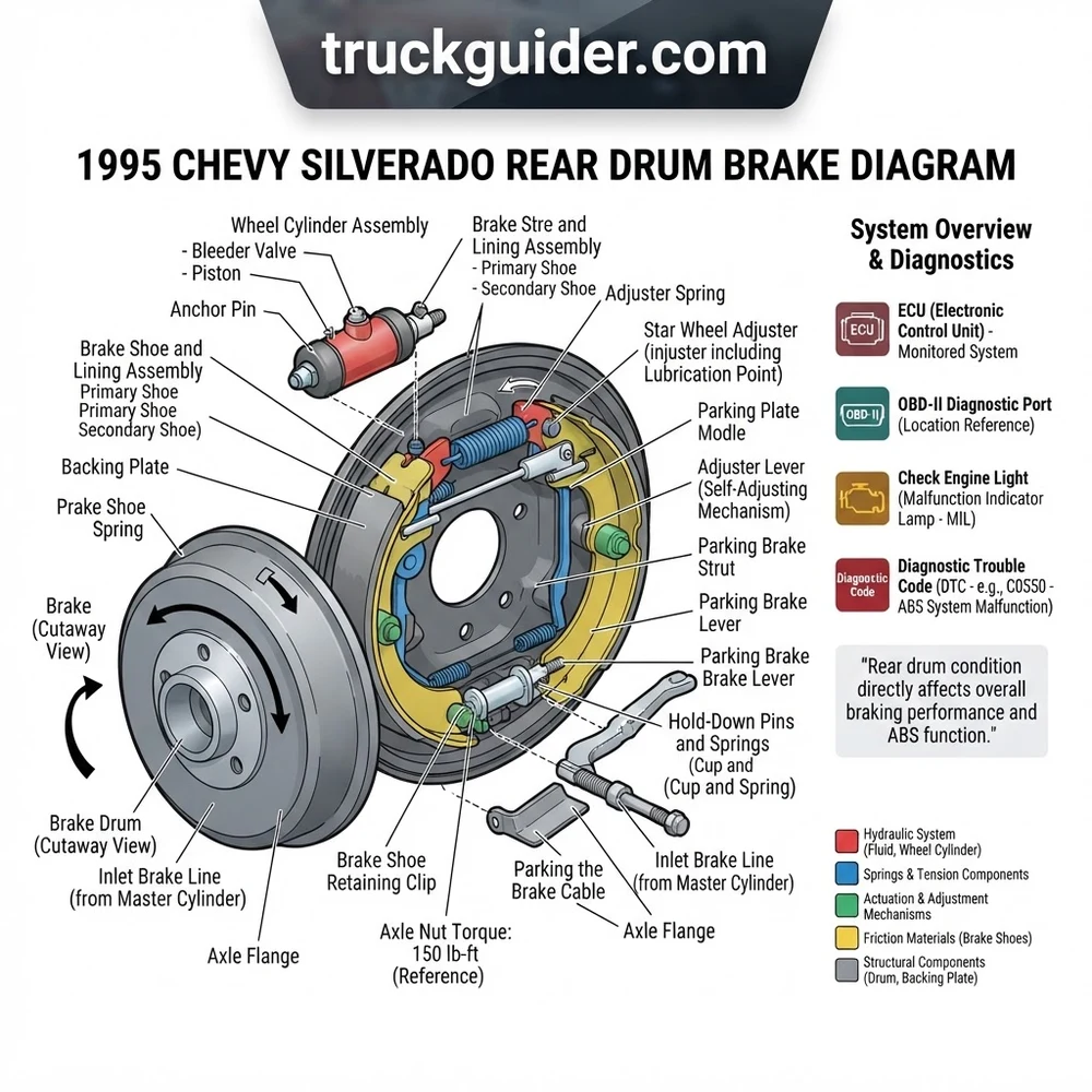
1995 Chevy Silverado Rear Drum Brake Diagram: Labeled Component Guide
Recommended Best Deal Products


The duo-servo drum system on the GMT400 platform utilizes the rotation of the brake drum to generate self-energizing braking action. When hydraulic line pressure enters the wheel cylinder, both brake shoes are forced outward. The rotating drum pulls the primary (forward-facing) shoe along its circumference, driving it down into the adjuster screw assembly. This transmitted kinetic force exerts mechanical leverage on the secondary (rear-facing) shoe, pressing it with multiplied force against the stationary anchor pin at the top of the backing plate. To service this system effectively, you must understand the positional relationship and mechanical duty of each component mapped on the assembly schematic.
| Callout ID | Component Name | Mechanical Location & Function | OEM Specification / Technical Notes |
|---|---|---|---|
| 1 | Backing Plate | Bolted directly to the rear axle housing flange via four Grade 8 studs. Features six stamped shoe-rest pads that require synthetic silicone lubricant. | Stamped heavy-gauge steel; inspect rest pads for grooves exceeding 0.015 in (0.38 mm). |
| 2 | Wheel Cylinder Assembly | Mounted at the top of the backing plate directly beneath the anchor pin. Houses dual opposing pistons, rubber cup seals, an expander spring, and a rear bleeder screw. | Bore: 1.00 in (JB5) or 1.0625 in (JB6/JB7); hydraulic port: 3/8-24 inverted flare fitting. |
| 3 | Primary Brake Shoe | Faces the front of the vehicle. Features a shorter friction lining positioned lower on the stamped steel web to initiate the servo self-energizing action. | Lining length is noticeably shorter than secondary shoe. Never install facing the rear of the truck. |
| 4 | Secondary Brake Shoe | Faces the rear of the vehicle. Features a longer friction lining running nearly the full arc of the steel web to absorb amplified mechanical wedging loads. | Carries the mechanical parking brake pivot pin; receives up to 75% of drum mechanical stopping load. |
| 5 | Anchor Pin | Fixed, hardened-steel post pressed or swaged into the backing plate top center. Both upper shoe webs rest against this pivot during rest and braking. | Supports the anchor pin guide plate and return spring loops. Must be checked for oval wear. |
| 6 | Primary Return Spring | High-tension coil spring hooking from the primary shoe web hole directly over the anchor pin post (often color-coded brown or green). | Installed beneath the secondary spring on the anchor post; holds primary shoe retract tension. |
| 7 | Secondary Return Spring | Hooks from the secondary shoe web to the anchor pin; secures the self-adjuster actuator cable guide or link (often color-coded yellow or blue). | Higher spring rate than primary; dampens severe servo vibrations during heavy braking deceleration. |
| 8 | Self-Adjuster Cable & Guide | A stamped steel track curved over the secondary shoe web routing a braided aircraft-grade wire cable linked from the anchor pin down to the adjuster lever. | Replace cable if frayed; plastic guide tracks must not be cracked or worn down by cable friction. |
| 9 | Adjuster Lever & Pawl | A stamped steel lever pinned to the secondary shoe web. The pawl tip indexes against the teeth of the star-wheel adjuster screw. | Ratchet lever actuates only when the vehicle applies brakes in reverse and lining travel is excessive. |
| 10 | Star-Wheel Adjuster Assembly | Three-piece threaded assembly (socket sleeve, threaded star wheel, and pivot cap) spanning the lowest portion of the primary and secondary shoe webs. | Handed threads: Left-hand threads on driver side (LH), right-hand threads on passenger side (RH). |
| 11 | Lower Adjusting Spring | Coil spring crossing underneath the star-wheel assembly; maintains continuous tension between lower shoe webs and prevents adjuster assembly fallout. | Must clear the star-wheel teeth without interference; coils position away from the adjuster pawl. |
| 12 | Shoe Hold-Down Pins & Springs | Hardened straight pins penetrating from the backside of the backing plate, locked through the shoe web via coiled springs and slotted retainer caps. | Keeps shoes planar against the backing plate pads without restricting radial sliding action. |
| 13 | Parking Brake Strut & Spring | Horizontal stamped steel spreader bar positioned directly below the wheel cylinder. Spans from the parking brake lever to the primary shoe web. | Equipped with an anti-rattle coil spring at the primary shoe web notch; prevents strut bind. |
| 14 | Parking Brake Actuator Lever | Heavy steel lever pinned to the secondary shoe web upper half; bottom clevis connects directly to the dynamic rear emergency brake cable. | Retained by a precision wave washer and horseshoe clip; must pivot freely without excessive endplay. |
When studying the 1995 chevy silverado rear drum brake diagram, note the critical vertical relationship between the wheel cylinder pushrods and the parking brake strut. The strut sits approximately 1.5 inches below the wheel cylinder center axis. Misplacing the anti-rattle spring or installing the strut backward jams the primary shoe web, preventing both shoes from returning fully. This creates massive frictional heat that boils the hydraulic fluid inside the wheel cylinder.
Every dynamic pivot point indicated on the diagram requires meticulous prep. Apply an ultra-thin film of high-temperature, molybdenum-disulfide or ceramic-based brake grease to the six backing plate raised pads, the anchor pin circumference, the parking brake strut contact notches, and the threads of the star-wheel adjuster screw. Never permit petroleum-based chassis grease to contact these components; operating temperatures inside the drum exceed 400°F (204°C), which liquefies general grease and contaminates friction linings.
On GMT400 trucks, the brake hardware springs lose up to 30% of their tension after three to four years of severe thermal cycling. Factory service procedures stipulate replacing the entire spring, hold-down pin, and cable kit every time friction shoes are replaced. Reusing fatigued springs leads to shoe drag, uneven friction taper, and premature lining wear.
1995 Silverado Drum Brake Sizes: JB5 vs JB6 Specs and Torque Spec Data

General Motors engineered multiple rear brake packages across the 1995 C/K truck line depending on Gross Vehicle Weight Rating (GVWR) and axle configuration. Simply ordering rear drum shoes for a “1995 Silverado 1500” frequently results in receiving the incorrect diameter or width. You must inspect the SPID label in your glovebox for the specific three-character RPO brake code before purchasing replacement drums, shoes, wheel cylinders, or overhaul kits.
| Metric Parameter | RPO JB5 (Light Duty 1/2 Ton) | RPO JB6 (Heavy Duty 1/2 & Light 3/4) | RPO JB7 / JD7 (Heavy Duty 3/4 Ton) |
|---|---|---|---|
| Nominal Drum Inside Diameter | 10.0 in (254.0 mm) | 11.15 in (283.2 mm) | 13.0 in (330.2 mm) |
| Maximum Discard Drum Diameter | 10.060 in (255.5 mm) | 11.210 in (284.7 mm) | 13.060 in (331.7 mm) |
| Brake Shoe Friction Width | 2.25 in (57.1 mm) | 2.75 in (69.8 mm) | 2.50 or 3.50 in (63.5 / 88.9 mm) |
| Wheel Cylinder Bore Size | 1.00 in (25.4 mm) | 1.0625 in (27.0 mm) | 1.1875 in (30.16 mm) |
| Axle Lug Configuration | 5-Lug (2WD) or 6-Lug (4WD) | 6-Lug (1500 HD / 4WD) | 8-Lug (Full-Float / Semi-Float 2500) |
| Axle Model Application | GM 8.5-inch 10-Bolt Semi-Float | GM 8.5″ or 9.5-inch 14-Bolt SF | GM 9.5″ or 10.5-inch 14-Bolt FF |
The JB5 package is standard on standard cab, short-bed two-wheel-drive C1500 trucks rated under 6,100 lbs GVWR. The JB6 package is the most prevalent configuration found across extended cab, four-wheel-drive K1500 trucks and heavy-half platforms (GVWR 6,400 to 7,200 lbs). The JB7 package applies strictly to C/K 2500 platforms running eight-lug wheel patterns. Cross-referencing your rear brake drum dimensions via a precision drum micrometer is mandatory before turning drums on a lathe or mounting replacement shoes.
Torque precision ensures backing plate stability and prevents fluid leaks at hydraulic connections under severe line pressures, which exceed 1,200 PSI during threshold braking events. You can review our detailed guides on brake master cylinder bore sizing, explore flaring brake hardlines, or reference our differential axle shaft seal replacement procedures to complement this overhaul.
• Wheel Lug Nuts (1/2″-20 Studs, 5/6 Lug): 100 lb-ft (140 N·m)
• Wheel Lug Nuts (9/16″-18 Studs, 8 Lug): 140 lb-ft (190 N·m)
• Wheel Cylinder Mounting Bolts (3/8″-16): 18 lb-ft (24 N·m)
• Hydraulic Brake Line Fitting (Flare Nut): 13 lb-ft (17 N·m)
• Wheel Cylinder Bleeder Valve Screw: 80 lb-in (9 N·m)
• Backing Plate-to-Axle Housing Flange Bolts: 55 lb-ft (75 N·m)
1995 Chevy Silverado Rear Drum Brake Diagram Problems and Symptoms
Recommended Best Deal Products


Duo-servo drum brakes generate balanced performance only when internal mechanics remain geometrically true. Due to the high number of tensioned components involved in the 1995 chevy silverado rear drum brake diagram, specific installation errors and mechanical failures occur frequently during field overhauls.
Reversed Primary and Secondary Shoe Orientation
The most widespread assembly error on GMT400 drum overhauls is interchanging the forward and rearward shoes. The primary shoe (short lining) must point toward the front bumper; the secondary shoe (long lining) must point toward the rear bumper. If you install the long-lining secondary shoe in the primary (forward) position, the mechanical self-energizing multiplier becomes hyper-aggressive. The drum grabs uncontrollably with minimal pedal pressure, locking up the rear axle, causing the truck to violently dart sideways under moderate braking, and producing rapid lining glazing.
Swapped Left and Right Star-Wheel Adjusters
The self-adjusting star-wheel assemblies are side-specific. The driver side assembly uses left-hand (LH) reverse threads, while the passenger side assembly uses right-hand (RH) standard threads. If a mechanic swaps these assemblies side-to-side, the ratcheting pawl lever will unthread the star wheel in reverse whenever the vehicle stops while traveling in reverse. Instead of expanding the shoes to compensate for wear, the adjuster closes the shoes. This results in progressive, excessive brake pedal travel and a dangerously low brake pedal drop.
Axle shaft seal failure on GM 8.5″ and 9.5″ semi-floating axles saturated drum assemblies with 80W-90 hypoid gear oil. Friction linings act like porous sponges: brake cleaner cannot completely purge oil saturated into organic or semi-metallic friction compounds. Oil-contaminated shoes will grab unexpectedly under low pedal pressure and slip uncontrollably under high pressure. Always replace saturated shoes and install new Timken/National wheel seals.
Worn Backing Plate Ledges and Shoe “Stepping”
Over hundreds of thousands of miles, the steel shoe webs dig grooves into the six raised stamped contact pads on the backing plate face. When these grooves exceed 0.015 inches, the shoe webs drop into the notches. As hydraulic line pressure builds, the shoes catch in these grooves instead of expanding smoothly. Symptoms include a distinct “clunk” sound on initial pedal application, a delayed brake release (truck feels tied down after stopping), or severe dynamic pull. Backing plates must have their pad surfaces ground flat with a light disc pass, filled with weld and ground level, or replaced entirely.
Stretched Cable Adjusters and Ratchet Jamming
The thin braided cable directing mechanical lift to the adjuster pawl lever stretches over time. A stretched cable alters the sweep angle of the lever across the star-wheel teeth. Instead of cleanly grabbing a single tooth and rotating the screw one notch, the pawl binds against the crown of a tooth or jumps the track entirely, locking the lower shoe webs out of planar alignment. This leads to high drum drag, severe localized thermal cracking of the cast-iron drum, and accelerated hub bearing failure.
Diagnosing 1995 Chevy Silverado Rear Drum Brakes Step by Step
Follow this systematic procedure using professional shop tools (including a brake shoe reset gauge, micrometer, and specialized brake spoon) to diagnose, measure, and tune the rear drum assemblies on your 1995 Silverado.
Step 1: Conduct Hydraulic and Powertrain Diagnostics
Before disassembling mechanical hardware, confirm the baseline operating state of the vehicle. In 1995, GM utilized an interim diagnostic system (often referred to as OBD-1.5 or early OBD-II physical port geometry running GM ALDL protocols). Connect a diagnostic scan tool capable of reading GM chassis parameters. While engine faults illuminate the Check Engine Light and register a powertrain diagnostic code in the ECU for issues like timing chain stretch, erratic coolant flow through the thermostat, or low oil pressure, brake problems register distinct chassis diagnostic codes inside the Kelsey-Hayes 4WAL or RWAL anti-lock brake module.
Confirm the red BRAKE warning light is extinguished on the dash cluster. If illuminated, inspect the proportioning valve switch stem below the master cylinder; an off-center spool indicates a catastrophic hydraulic pressure differential between the front disc and rear drum circuits. Check fluid condition: dark, water-contaminated DOT 3 brake fluid degrades wheel cylinder rubber cups and drops fluid boiling point drastically.
Step 2: Elevate Axle, Remove Drums, and Triage Fluid Leaks
Chock the front tires securely. Raise the rear axle housing using a hydraulic floor jack rated for at least 3 tons and lower the chassis onto jack stands positioned directly beneath the leaf spring perches. Disengage the in-cab parking brake pedal completely. Remove the rear wheel lug nuts and take off the wheel assemblies. Slide the brake drums off the axle studs.
If the drum is locked tight against the shoes due to a rust ridge on the inner drum lip, use a standard flat-blade screwdriver and a curved brake spoon through the oval inspection slot on the lower backing plate. Push the adjuster pawl lever back away from the star wheel using the screwdriver, then rotate the star wheel upward using your brake spoon to retract the shoes, allowing the drum to slip free. Pull the rubber dust boots back on the wheel cylinder; any liquid brake fluid leaking past the internal pistons signals an immediate need for cylinder replacement or honing.
Step 3: Measure Friction Linings and Drum Tolerances
Utilize a precision vernier caliper or dedicated brake lining gauge to measure the friction material thickness at the thinnest section of both shoes. Factory GM specifications dictate a minimum friction lining thickness of 2/32 in (0.0625 in / 1.58 mm) above the steel web or rivet heads. If the lining shows uneven, wedge-shaped taper from top to bottom, the hold-down spring tension is uneven or the wheel cylinder pistons are sticking in their bores.
Next, clean the inner swept surface of the cast-iron drum with brake cleaner. Deploy an inside drum micrometer to measure the internal diameter at three alternating 60-degree angles across both the inner and outer friction track. Compare these measurements against the maximum discard diameter stamped onto the outer casing edge of the drum (e.g., “MAX DIA 10.060 IN” or “MAX DIA 11.210 IN”). If the measured diameter exceeds the stamped discard spec, or if out-of-round runout exceeds 0.006 in (0.15 mm), the drum must be replaced immediately. Over-machined drums flex under heavy hydraulic loads, inducing pedal pulsation and severe brake fade.
Step 4: Clean Backing Plate and Service Contact Pads
Disassemble the return springs using specialized drum brake spring pliers (avoid using locking pliers, which score spring coils and create stress-riser failure points). Remove the hold-down pins, retainer cups, parking brake strut, and lower adjuster mechanism. Strip the backing plate completely. Clean away all built-up friction dust using solvent-based brake wash.
Inspect the six raised steel rubbing pads on the backing plate for groove depression. If completely flat, smooth them using 120-grit emery cloth to clear surface scale. Wipe down the metal and apply a thin, uniform coating of high-temp synthetic brake grease (NLGI Grade 2 silicone base with PTFE/Moly) to all six pads. Coat the threads of the star wheel assembly with anti-seize paste, verify that the assembly spins freely across its entire threaded stroke, and ensure the adjuster pawl teeth are sharp and unrounded.
Step 5: Reassemble Hardware and Validate Mechanical Geometries
Reinstall the parking brake lever onto the secondary shoe web, inserting a new GM horseshoe clip and crimping it closed with slip-joint pliers until all side-to-side endplay is eradicated. Set the secondary shoe against the rear backing plate pads and insert its hold-down pin, spring, and retainer cup, rotating the cup 90 degrees to lock the pin flat into the retainer slot. Install the primary shoe in the identical fashion on the forward side of the plate.
Slot the parking brake strut and anti-rattle spring into position directly beneath the wheel cylinder. Position the self-adjuster cable eyelet over the anchor pin, followed by the anchor pin guide plate. Hook the primary return spring over the anchor pin using your spring tool, followed by the secondary return spring. Route the cable over the secondary guide bracket and hook it into the adjuster lever pivot. Install the lower adjusting spring across both lower shoe webs, ensuring the star wheel assembly is situated with the star wheel teeth facing the rear of the truck (on both sides) to match pawl alignment.
Step 6: Calibrate Mechanical Pre-Adjustment and Dynamic Road Test
Do not rely on the vehicle’s automatic adjusters to take up the massive initial gap of new shoes. Set a brake shoe reset gauge to the exact inside diameter of the brake drum. Lock the tool’s setting thumb screw. Flip the tool over and place it over the outside circumference of the newly installed shoes on the backing plate. Manually click the star wheel outward using your fingers or a brake spoon until the shoe linings just scrape the gauge contacts.
Slide the brake drum over the axle flange. It should seat smoothly with a barely audible, light friction drag as you spin the drum by hand. Reinstall the wheels and torque the lug nuts in a criss-cross pattern to factory torque spec (100 lb-ft for 5/6-lug; 140 lb-ft for 8-lug). Pump the brake pedal 5 times with the engine running to center the duo-servo shoe geometry against the anchor pin. Road test the vehicle: perform 8 to 10 moderate stops from 35 MPH in reverse, followed by firm forward stops, to finalize the ratcheting self-adjuster calibration.
1995 Chevy Silverado Rear Drum Brake Diagram Questions Answered
Recommended Best Deal Products


How do I tell the primary brake shoe from the secondary shoe on a 1995 Silverado?
Inspect the physical length of the friction material bonded or riveted to the stamped steel shoe web. The primary shoe features a noticeably shorter friction lining arc and must always be installed facing forward toward the front of the truck. The secondary shoe features a significantly longer friction lining running almost the entire length of the curved steel web and must always face the rear of the vehicle. The secondary shoe also features the mounting hole for the parking brake lever pivot pin.
Why is the brake pedal low on my 1995 Silverado even after bleeding the hydraulic lines?
A low brake pedal on a GMT400 truck with properly bled hydraulic lines is almost always caused by improper rear drum brake shoe-to-drum clearance. Because duo-servo drum brakes require significant fluid displacement to push retracted shoes against the drum walls, excessive air gap at the rear shoes swallows up master cylinder piston stroke before friction occurs. Manually adjust the star-wheel adjusters outward through the backing plate slots until the shoes contact the drum, then back off 3 to 4 clicks until the wheel turns with light drag.
Can a failing rear axle seal ruin newly installed rear drum brakes?
Yes. The semi-floating rear axles (GM 8.5″ 10-bolt and 9.5″ 14-bolt) utilize internal C-clips at the differential and depend on a pressed outer oil seal at the end of the axle tube. When this seal hardens, scores, or fails, high-viscosity gear lubricant sweeps down the axle shaft tube and is slung by centrifugal force throughout the interior of the brake drum. The brake shoe friction linings immediately absorb this gear oil, completely destroying their frictional coefficient and creating dynamic grabbing or total brake loss on that corner.
What is the proper orientation of the star-wheel adjusters on each side of the truck?
The star-wheel adjusters are strictly side-specific and cannot be interchanged. The adjuster with left-hand (reverse) threads mounts on the driver side (left side) of the vehicle. The adjuster with right-hand (standard) threads mounts on the passenger side (right side) of the vehicle. When installed correctly on both sides, the star-wheel teeth sit toward the rear of the truck, positioned directly adjacent to the ratcheting pawl lever attached to the secondary shoe web.
Does a loose rear drum brake adjustment trigger a Check Engine Light or ABS code?
A mechanical rear drum brake adjustment issue will not trigger an engine diagnostic code or illuminate the Check Engine Light via the powertrain ECU. However, extreme mechanical drum clearance can alter the wheel speed decay rate during threshold stops. This variance is detected by the rear wheel speed sensor (VSS) mounted on the transmission or transfer case tailhousing, which communicates with the Kelsey-Hayes RWAL/4WAL module. If wheel lockup or speed differential is detected outside baseline tables, the amber ABS warning lamp illuminates and logs an ABS chassis diagnostic code.
Step-by-Step Guide to Understanding the 1995 Chevy Silverado Rear Drum Brake Diagram
Identify – Clean the assembly and identify primary and secondary shoes, matching friction lining length against the schematic.
Locate – Locate the upper anchor pin, hydraulic wheel cylinder ports, lower adjuster mechanism, and backing plate contact pads.
Reference – Reference the diagram to verify the orientation of the star-wheel adjuster, ensuring left- and right-hand threads are correct.
Connect/Route – Route the parking brake cable through the backing plate, attaching the lever and installing return springs onto the anchor pin.
Verify – Verify drum clearance by rotating the assembly, then torque wheel cylinder bolts to the 15 ft-lbs torque spec.
Troubleshoot – Troubleshoot a spongy pedal by bleeding hydraulic lines, and scan the OBD-II or ALDL interface if a diagnostic code appears.