1995 Ford F150 Fuse Box Diagram: 2026 Repair Guide

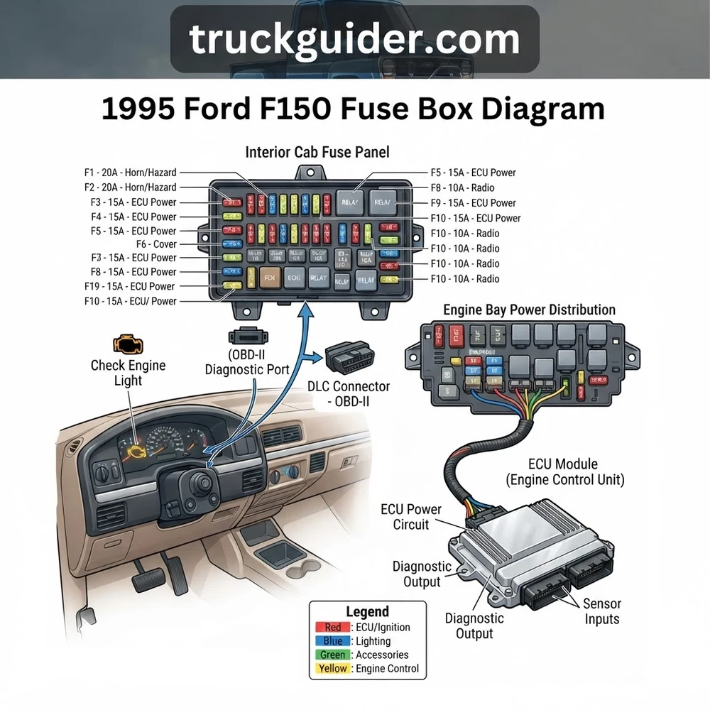
The 1995 Ford F-150 features an interior fuse panel beneath the steering column and an engine compartment Power Distribution Box near the driver-side fender. Fuse #13 (15A) powers brake/hazard lights, while Fuse #18 (15A) feeds the instrument cluster. Maxi-fuses in the engine bay feed the ECU and fuel pump relays.
📌 Key Takeaways
- Interior fuse panel houses 18 standard ATO blade fuses rated 4A to 30A beneath the dash.
- Underhood Power Distribution Box utilizes high-amp Maxi-fuses (20A–60A) and Bosch-style mini-relays.
- Battery terminal clamps require a torque spec of 71-106 in-lbs (8-12 Nm) to avoid voltage drops.
- Melted fuel pump relay sockets and corroded Maxi-fuse terminals are the top electrical failure points.
- Basic fuse replacement is DIY-friendly; burnt internal busbars or shorted harness runs require professional repair.
The ninth-generation (OBS) Ford F-Series relies on a dual-panel electrical distribution architecture designed to isolate high-amperage engine bay demands from sensitive cab-mounted electronics. When troubleshooting electrical faults on this platform, consulting an accurate 1995 Ford F150 fuse box diagram is essential for isolating short circuits, tracking parasitic draws, and pinpointing failed relays. Ford implemented running production changes throughout the 1995 model year—notably within the engine management architecture as California emissions configurations transitioned from EEC-IV to early OBD-II protocols. This guide provides exact pinouts, wire color codes, current load limits, and diagnostic workflows across both the underhood Power Distribution Box and the interior cabin fuse block.


1995 Ford F150 Fuse Box Diagram and Panel Locations
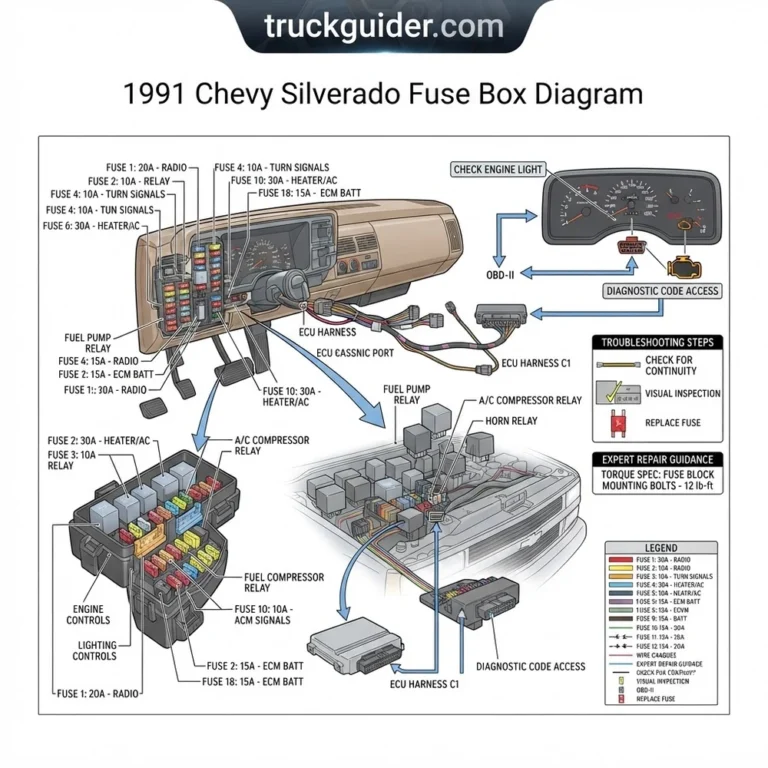
The electrical system of the 1995 Ford F-150 distributes power through two distinct enclosures: the interior passenger compartment fuse panel and the underhood Power Distribution Box (PDB). Understanding the physical routing and architecture of these assemblies prevents misdiagnosis when voltage drops occur between the ignition switch, battery supply bus, and terminal loads.
Ninth-generation Ford trucks utilize two distinct styles of overcurrent protection: standard ATO/ATC fast-acting blade fuses inside the cabin, and high-amperage Maxi fuses paired with ISO-standard micro and mini relays inside the underhood Power Distribution Box. Never interchange an ATC (closed) fuse with an open-element alternative in exposed engine bay harnesses.
Underhood Power Distribution Box Physical Mounting

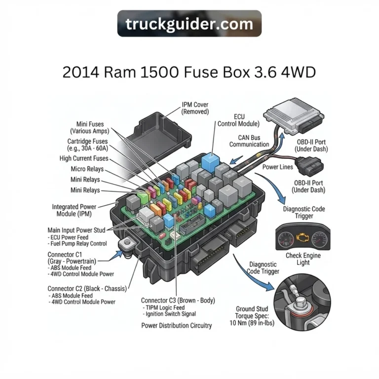
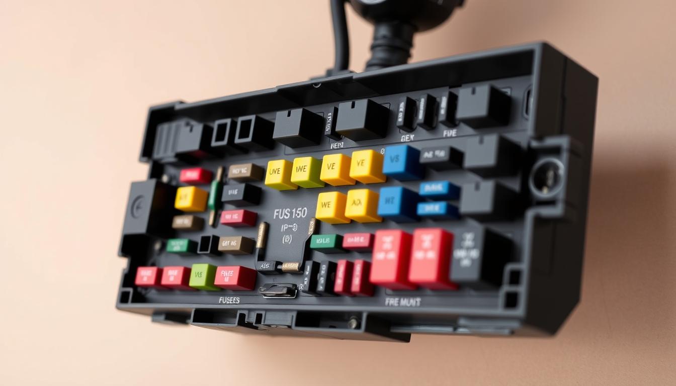
The underhood Power Distribution Box is positioned on the driver-side inner fender apron, directly aft of the primary 12-volt battery tray and forward of the master cylinder assembly. Encased in a rigid, heat-resistant thermoplastic housing, this box receives unfused, direct 12V continuous positive battery current via a heavy 4-gauge or 6-gauge battery feeder cable connected to the starter relay (solenoid) battery stud terminal. The enclosure features a snap-fit weather-sealed cover secured by dual side-locking tabs. Over time, engine bay heat cycles and exposure to high coolant flow temperatures from the radiator bypass hose can cause these tabs to become brittle; apply gentle inward pressure on the release clips to prevent fracturing the cover tabs.
The PDB houses Maxi fuses ranging from 20A to 60A that provide primary circuit protection before power transitions into the cab. It also contains the heavy-duty electromagnetic relays that switch current to the electric in-tank fuel pumps, horn assembly, air conditioning clutch, and the electronic engine management computer. If you are servicing related systems, refer to our comprehensive guide on Ford Truck Relay Diagnostics and Pinouts.
Interior Cab Fuse Panel Access and Architecture
The interior cab fuse panel is mounted underneath the driver-side lower instrument panel dashboard, positioned to the left of the steering column assembly near the parking brake mechanism. Accessing the panel requires removing the protective, molded trim cover. Pull the bottom thumb notch firmly toward the driver seat to disengage the spring clips.
The interior block utilizes standard ATO/ATC fast-acting automotive blade fuses (rated up to 32V DC) arrayed in numbered vertical columns alongside integrated thermal circuit breakers. The panel also accommodates the turn signal flasher and the hazard warning flasher canisters. Cab panel power is routed from specific Maxi fuses located in the underhood PDB; consequently, an entire row of non-functional cabin fuses typically indicates an open circuit upstream at the PDB rather than multiple simultaneous interior fuse failures. For supplemental wiring references across neighboring production years, consult the 1994–1996 Ford F-150 Chassis Wiring Guide.
Cab Panel Retaining Fasteners: Quarter-turn push clips; Power Distribution Box Main Battery Feed Stud Nut: 5/16-18 thread, OEM tightening torque spec: 80–100 lb-in (9.0–11.3 Nm). Excessive torque will fracture the internal copper bus bar.
1995 Ford F150 Fuse Box Layout and Circuit Assignment Tables
The following factory-matched circuit assignment tables detail the precise fuse identifications, amperage ratings, and assigned electrical loads for both panels on the 1995 Ford F-150.


Underhood Power Distribution Box Circuit Directory
The high-current underhood box routes unfused battery voltage through high-capacity Maxi fuses to primary relays, ignition switches, and downstream cabin distribution points. As shown in the diagram above, components are organized with Maxi fuses occupying positions along the outer rows and standard plug-in relays seated along the central spine.
| Position / ID | Rating | Circuit Function & Protected Components |
|---|---|---|
| Maxi Fuse A | 30A | Trailer Tow Electronic Brake Controller Package |
| Maxi Fuse B | 20A | Engine Cooling / Auxiliary Electric Fan (Heavy Duty cooling package) |
| Maxi Fuse C | 50A | Cab Fuse Panel Main Bus 1 (Feeds cab fuses 4, 8, 12, 16) |
| Maxi Fuse D | 20A | Fuel Pump Relay (Feed to inertia switch, dual tank selector, in-tank pumps) |
| Maxi Fuse E | 50A | Cab Fuse Panel Main Bus 2 (Ignition switch power, Starter relay trigger feed) |
| Maxi Fuse F | 30A | Powertrain Control Module (ECU power relay coil and switched battery load) |
| Maxi Fuse G | 40A | Trailer Tow Battery Charge Relay & Exterior Lights Backup Feed |
| Maxi Fuse H | 30A | Anti-Lock Brake System (4-Wheel or Rear-Wheel ABS hydraulic module) |
| Maxi Fuse I | 50A | Blower Motor Relay (High fan speed resistor feed and climate controls) |
| Maxi Fuse J | 50A | Cab Fuse Panel Main Bus 3 (Headlamps, tail lamps, hazard flasher bus) |
| Relay 1 | ISO Micro | Powertrain Control Module (ECU) Power Relay |
| Relay 2 | ISO Micro | Fuel Pump Relay |
| Relay 3 | ISO Micro | Air Conditioning (A/C) Wide Open Throttle (WOT) Cutoff Relay |
| Relay 4 | ISO Micro | Horn Relay |
| Relay 5 | ISO Micro | Trailer Tow Battery Charge Relay |
Interior Cabin Passenger Compartment Fuse Block Directory
The interior dash fuse block utilizes color-coded fast-acting ATC blade fuses that safeguard secondary accessories, safety restraints, and dashboard cluster instruments.
| Fuse # | Amperage | Color | Circuits / Devices Protected |
|---|---|---|---|
| 1 | 15A | Blue | Stop/Hazard Lamps, Anti-Lock Brake System module trigger |
| 2 | — | — | Not Used / Unassigned Open Cavity |
| 3 | 15A | Blue | Courtesy Lamps, Dome/Cargo Light, Speedometer memory |
| 4 | 15A | Blue | Exterior Turn Signals, Back-up lamps, Daytime Running Lights |
| 5 | — | — | Not Used / Open Option Slot |
| 6 | 15A | Blue | Rear Window Defroster Control Switch, Heated Mirrors |
| 7 | — | — | Not Used / Open Option Slot |
| 8 | 20A C.B. | Silver Metal | Power Door Locks, Power Tailgate Release Switch |
| 9 | 30A | Green | Windshield Wiper Motor, Windshield Washer Fluid Pump |
| 10 | — | — | Not Used / Open Option Slot |
| 11 | — | — | Not Used / Open Option Slot |
| 12 | 20A C.B. | Silver Metal | Power Windows (Front Driver/Passenger Regulators) |
| 13 | 15A | Blue | Cigarette Lighter socket, Data Link Connector (OBD-I / EEC-IV) |
| 14 | 20A C.B. | Silver Metal | Power Lumbar Adjustment, Electric Driver Seat Tracks |
| 15 | — | — | Not Used / Open Option Slot |
| 16 | 15A | Blue | Instrument Panel Dimming, Ash Tray illumination, Radio dial |
| 17 | 10A | Red | Airbag Supplemental Restraint System (SRS) Electronic Control |
| 18 | 15A | Blue | Instrument Cluster Gauges: Fuel level, Tachometer, Voltmeter |
Positions 8, 12, and 14 are designed specifically for metallic auto-reset thermal circuit breakers. Installing standard plastic ATO/ATC blade fuses in these locations can result in premature fuse failure or terminal melt down caused by in-rush current surges from cycling electric window and lock motors.
Blown Fuse Symptoms: Check Engine Light, No-Start, and Power Loss
Diagnosing an electrical malfunction on a 1995 F-150 requires matching distinct engine performance issues or interior failures with the responsible overcurrent protective device. Below is a symptom-to-circuit correlation analysis to expedite your troubleshooting:
- Engine Cranks Continuously But Refuses to Fire (No-Start): If the starter relay engages the starter motor normally but the engine exhibits no combustion, inspect underhood Maxi Fuse F (30A) and Relay 1 (ECU Power Relay), followed by Maxi Fuse D (20A) and Relay 2 (Fuel Pump Relay). A failure of Maxi Fuse F cuts all power to the EEC-IV / OBD-II engine control computer, disabling injector pulsing and distributor TFI-IV module spark excitation. When this occurs, the fuel pump will not prime for its standard two-second cycle when the ignition is keyed to RUN.
- Check Engine Light Inoperative During Key-On Bulb Check: If the instrument cluster fails to illuminate the check engine light (CEL) when the ignition is switched to RUN prior to cranking, the ECU has lost operating power, or interior Fuse 18 (15A) has blown. With no power reaching the diagnostic circuitry, retrieving an active diagnostic code via an OBD-I code reader or diagnostic jumper wire across the STI/STO connector is impossible.
- Dead Instrument Cluster Gauges with Zero Oil Pressure Reading: If your cluster gauges drop to their zero baseline while driving—specifically the engine oil pressure, coolant temperature, voltmeter, and fuel quantity needles—interior Fuse 18 (15A) has blown. While a true drop in mechanical oil pressure indicates worn journal bearings or oil pump failure, an instant zero-reading on the gauge paired with dead fuel indicators points entirely to the Fuse 18 terminal bus.
- Intermittent Misfire Under Load or Sudden Engine Stalling: A hairline fatigue crack in Maxi Fuse F (30A) can maintain static continuity at idle but experience thermal expansion under heavy electrical load, cutting ignition power intermittently. This can mimic the physical symptoms of a stretched timing chain or advanced ignition distributor gear wear, generating false diagnostic code outputs for PIP (Profile Ignition Pickup) sensor fault.
- Erratic Shift Strategy on E4OD Automatic Transmissions: On trucks equipped with the electronically controlled 4-speed E4OD automatic transmission, a blown cabin Fuse 1 (15A) or Fuse 13 (15A) deprives the solenoid pack of stable voltage reference. This triggers harsh shifts, late upshifts, or flashes the “OD OFF” switch light while logging diagnostic codes associated with the electronic pressure control (EPC) actuator.
Diagnosing 1995 Ford F150 Fuse Box Circuit Faults Step by Step
Identifying whether an electrical failure is caused by an open fuse, a corroded terminal socket, or a downstream dead short requires a structured diagnostic protocol. Use a commercial 12-volt incandescent test light and an automotive digital multimeter (DMM) with needle-probe attachments.
- Perform a Closed-Circuit Voltage Drop Verification:
Connect the alligator ground clamp of your test light or black DMM lead to a clean chassis ground, such as the negative battery terminal or steering column mounting stud. Turn the ignition switch to the RUN position to energize switched accessory circuits. Probe both exposed metal test tabs on the back of each blade fuse inside the cab panel. If your test light illuminates on one terminal tab but remains dark on the opposite tab, the internal sacrificial zinc element is open. If neither tab illuminates, that circuit is switched off, or upstream supply power from the PDB is absent. - Isolate Intermittent or Latent Downstream Short Circuits:
When a replacement fuse blows instantly upon insertion, do not install a higher amperage fuse. Remove the blown fuse and insert a dedicated automotive short-circuit detector or wire a 12V automotive light bulb (such as an 1157 stop lamp) across the load and supply terminals of the fuse cavity. If a short to ground is present along the harness, the test bulb will glow at full brightness. Flex the wiring harness along the engine block, near hot exhaust components, and around firewall pass-through grommets. When the bulb flickers or extinguishes, you have pinpointed the harness chafing zone. - Measure Parasitic Battery Drain Across the Fuse Panels:
Switch off all vehicle accessories, extract the ignition key, and close the doors to allow the interior lamp timeout modules to settle. Disconnect the negative battery cable terminal clamp. Configure your digital multimeter to measure DC Milliamperes (mA) and bridge the meter leads in series between the negative battery post and the disconnected negative cable end. A baseline parasitic draw on an OBS Ford F-150 should not exceed 30 to 50 mA (drawn primarily by the radio clock memory and EEC-IV keep-alive memory). If the reading exceeds 100 mA, pull each interior cabin fuse sequentially while watching the meter display. The circuit that causes the amperage to drop to normal levels when removed contains the parasitic drain fault. - Inspect for Terminal Pin Corrosion and Fretting:
Remove high-draw fuses and relays from the underhood Power Distribution Box and inspect the internal female spade receptacles using a high-intensity inspection light. Look for green copper oxide discoloration or loose terminal tension. Terminal corrosion introduces parasitic resistance, which drops the operating voltage supplied to critical sensors like the distributor Hall-effect switch, throttle position sensor, and coolant flow temperature sending units. Clean oxidized terminals using non-residue electrical contact cleaner and micro-abrasive wire terminal picks.
Fuse Box Terminal Upgrades, Torque Specs, and Wiring Repairs
When running aftermarket auxiliary loads—such as auxiliary off-road lights, high-output stereo amplifiers, or electric trailer brake controllers—never tap directly into existing low-amperage cabin harness wiring. Splicing into the ignition switch or instrument cluster power wires will overheat factory traces and cause voltage drop across the instrument cluster.
Primary Power Distribution Box Feeder Cable Nut: OEM torque spec is 80–100 lb-in (9.0–11.3 Nm). Alternator Output Stud (B+ Terminal): 80–90 lb-in (9.0–10.2 Nm). Auxiliary Add-A-Circuit limit: Do not exceed 10A per individual branch circuit tap.



To safely add 12-volt circuits, install an ATC add-a-circuit dual fuse adapter into an unassigned or low-load ignition-switched fuse slot (such as slot 4 or 6, assuming options are absent), ensuring the total combined draw does not exceed the bus rating. For high-amperage components drawing more than 20 amps, wire an independent sealed inline Maxi fuse holder or supplemental marine-grade relay block directly to the battery-positive stud of the starter relay on the passenger inner fender. Secure all terminal eyelets to the stud and torque the retention nut strictly to 80–100 lb-in. Over-tightening will strip the copper stud threads, while under-torquing promotes arcing, thermal degradation, and erratic voltage delivery to the engine ECU.
1995 Ford F150 Fuse Box Diagram FAQs and Solutions
Where is the fuel pump fuse and relay located on a 1995 Ford F-150?
The primary fuel pump circuit is protected by Maxi Fuse D (rated at 20A) and switched via Relay 2 inside the underhood Power Distribution Box, mounted on the driver-side fender apron. From Relay 2, power routes through the safety inertia switch located behind the cab passenger-side kick panel, then to the dashboard fuel tank selector switch (on dual-tank configurations), and ultimately to the selected in-tank low-pressure/high-pressure fuel pump assembly.
Is the 1995 Ford F-150 equipped with OBD-I or OBD-II diagnostics?
The majority of 1995 Ford F-150 trucks sold across North America are equipped with Ford’s EEC-IV OBD-I system, featuring the triangular Data Link Connector (DLC) and separate single-pin STI pigtail located in the engine compartment near the driver-side hood hinge. However, 1995 models equipped with the 5.0L (302 CID) V8 engine, automatic transmission, and California emissions control utilize early OBD-II (EEC-V). On these specific California configurations, the diagnostic code reader connects to a standard 16-pin OBD-II port located inside the cab, mounted directly underneath the passenger-side dashboard lower trim.
Why does my 1995 F-150 experience a no-start with no diagnostic codes logged?
When an engine cranks normally but will not start, and jumping the underhood EEC-IV test port fails to flash the check engine light for diagnostic code readout, the ECU is not receiving operating voltage. This condition is almost exclusively caused by a blown 30A Maxi Fuse F or a failed Relay 1 inside the underhood Power Distribution Box. Without power through this circuit, the engine computer cannot energize fuel injection drivers or establish communication with diagnostic equipment.
Can I replace the metal circuit breakers in my cab panel with regular blade fuses?
No, you should never replace the original metal-cased thermal circuit breakers in slots 8, 12, or 14 with standard ATC blade fuses. Those positions supply high in-rush inductive loads for the power door lock solenoids, power seat actuators, and electric window regulator motors. When a window reaches the top of its track, current spikes significantly; a standard fuse will blow immediately, whereas the OEM thermal circuit breaker temporarily opens internally, cools down within seconds, and automatically resets.
What causes the interior cab fuse box to get warm or smell like hot plastic?
Excessive heat radiating from the interior fuse block typically stems from terminal corrosion or loose mechanical tension inside the female terminal clips. Decades of vibration cause the terminal leaves to relax their clamping grip on the fuse blades. This loose mechanical fit introduces contact resistance. In accordance with Ohm’s Law, electrical resistance under continuous load generates localized thermal energy that melts the plastic fuse casing long before the fuse reaches its amperage blow rating. If thermal deformation is visible, extract the affected fuse terminal with a release pick and either re-tension the spring leaves or crimp on a replacement Ford-spec female terminal.
Step-by-Step Guide to Understanding the 1995 Ford F150 Fuse Box Diagram
Identify – Inspect the symptom, trace the affected load circuit, and locate the primary fuse using the 1995 Ford F150 fuse box diagram.
Locate – Access the cabin panel under the lower-left dash trim or open the underhood distribution box adjacent to the air cleaner assembly.


Reference – Match the numbered diagram position to the installed fuse, checking for the correct factory amperage rating and circuit description.
Connect/Route – Remove the fuse with a plastic puller, examine the internal element for breaks, and insert an identical-rated replacement without forcing.
Verify – Turn the ignition on, operate the accessory or crank the engine, and verify full 12.6V battery voltage across test points.
Troubleshoot – If the fuse blows instantly, isolate harness connectors along the run, inspect for pinched wiring, and check the ECU for a related diagnostic code.