1995 GMC Sierra Fuse Box Diagram: 2026 Repair Guide

The 1995 GMC Sierra features two main fuse blocks: the primary cabin panel on the driver-side dash edge behind a removable access cover, and the underhood relay center mounted near the brake booster. The 20A ECMB fuse powers the fuel pump relay and ECU, maintaining standard ATO blade configurations across circuits.
📌 Key Takeaways
- The interior panel uses standard 3A to 30A fast-acting ATO/ATC blade fuses operating at 12V DC nominal.
- Crucial circuits: ECM-B (20A) feeds the fuel pump and ECU, while ECM-I (15A) powers ignition coils and fuel injectors.
- Terminal mounting studs on the underhood convenience center require a torque spec of 85 lb-in (9.6 Nm).
- Oxidation on the behind-the-dash grounding bus bar frequently triggers an intermittent check engine light.
- Perform simple fuse continuity checks via DIY; replace burnt terminal blocks or damaged ECU wiring through professional service.
The 1995 GMC Sierra represents a pivotal transitional year for General Motors GMT400 platform trucks, bridging classic OBD-I powertrain electronics with updated interior architecture and early OBD-II physical diagnostic interfaces. Properly troubleshooting electrical distribution faults on this platform requires a rigorous understanding of the cabin fuse block, the underhood convenience center, and auxiliary relay junctions. Whether you are tracking a no-start condition stemming from ECU power loss, addressing erratic instrument cluster readings caused by grounded sensor references, or analyzing an illuminated check engine light triggering a stored diagnostic code, this comprehensive 1995 GMC Sierra fuse box diagram manual provides the component layouts, amperage allocations, wiring designations, and diagnostic procedures necessary to service your vehicle to original manufacturer specifications.


1995 GMC Sierra Fuse Box Diagram: Panel Locations and Components

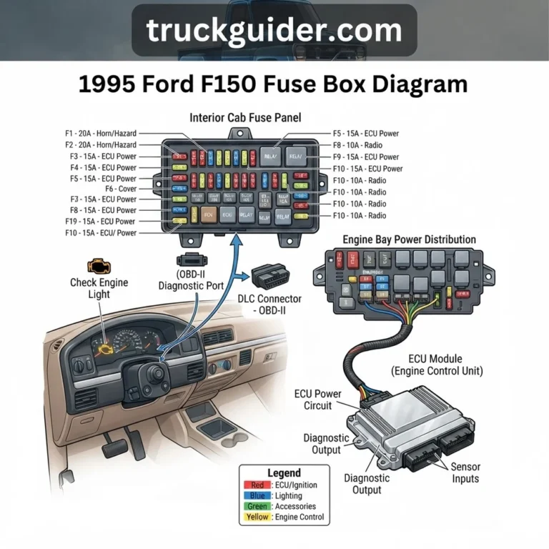
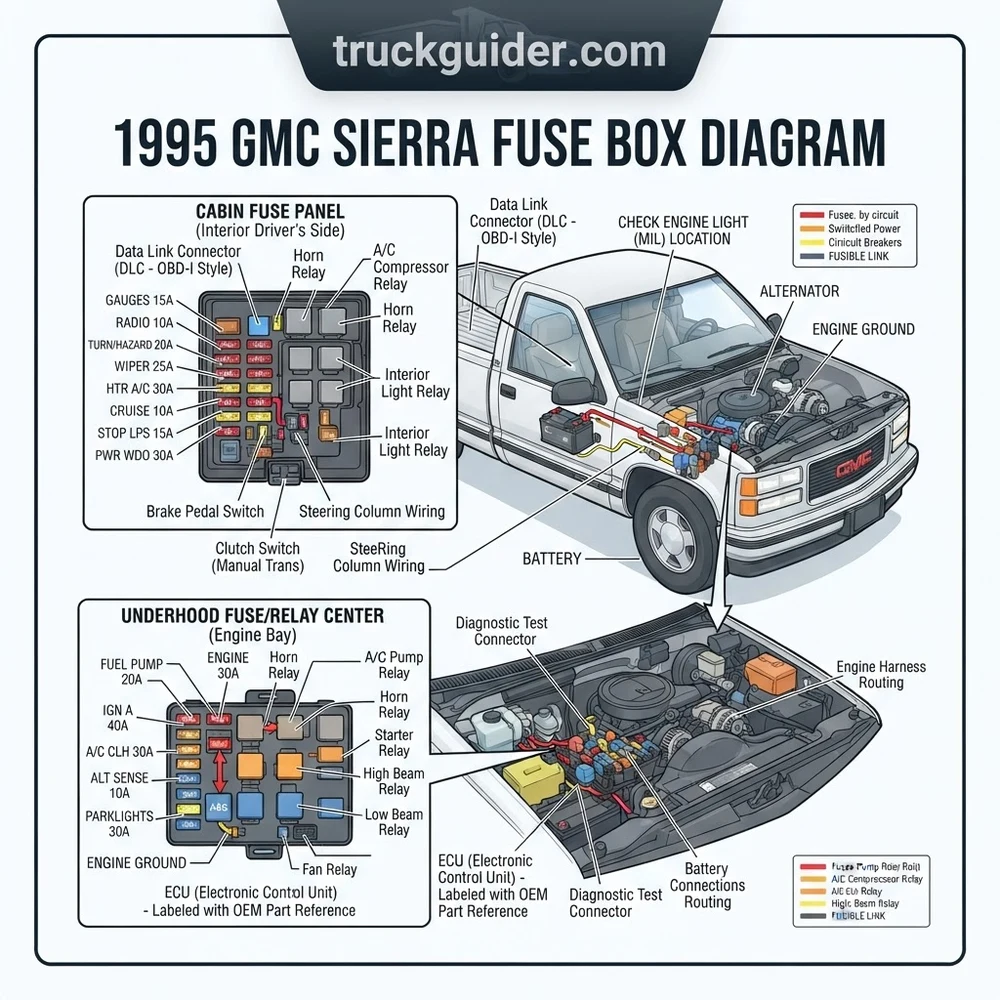
General Motors engineered the 1995 Sierra (encompassing C/K 1500, 2500, and 3500 platforms) with split electrical distribution architectures. Circuit protection is split across two primary hubs: the Instrument Panel Fuse Block located inside the passenger cabin and the Underhood Convenience/Relay Center positioned inside the engine bay on the driver-side firewall. Gaining access to these panels and identifying the sub-components requires precise knowledge of the GMT400 dash and engine bay layout.
Instrument Panel Fuse Block Location and Access

The interior fuse block is integrated directly into the structural dashboard sub-frame on the driver side. To access this panel, open the driver-side door and locate the removable access panel on the lower-left edge of the dashboard assembly, adjacent to the emergency brake pedal mechanism. Pulling the retention finger tab releases the panel cover from its spring clips. The interior face of this removable cover contains an abbreviated molded schematic identifying fuse designations and circuit amperages. This panel houses standard blade fuses (ATC and ATO formats) that regulate cabin comfort, dash instrumentation, body lighting, and key low-draw sensor triggers tied directly to ignition switch run/start circuits.
Underhood Convenience and Relay Center Layout
Heavy-duty, high-amperage engine functions, including high-current heating, powertrain loads, and secondary ignition controls, are centralized in the Underhood Convenience Center. On the 1995 Sierra, this enclosure is mounted directly to the engine-bay cowl bulkhead on the driver side, situated above the master cylinder and brake booster assembly. The enclosure is secured with a threaded retention thumb-screw or perimeter retention tabs on a high-density black thermoplastic housing. Removing this cover reveals high-capacity Maxi fuses, heavy-duty automotive relays (such as the fuel pump and air conditioning compressor relays), and the primary junction stud providing continuous 12-volt battery power from the starter harness.
The 1995 model year features a redesigned dashboard layout distinct from 1988–1994 trucks, moving several accessory circuit breakers and flasher modules into the dash block. Furthermore, while 1995 GM trucks frequently feature the 16-pin DLC (Data Link Connector) typically associated with OBD-II standards, the onboard ECU runs transitional OBD 1.5 code algorithms. Proper pin-out verification between the fuse block and the ALDL/DLC port is critical when retrieving any diagnostic code with a scan tool.
Blade Fuses, Maxi Fuses, and Circuit Breakers Defined
The 1995 Sierra utilizes three primary electrical protection technologies across its panels:
- Blade Fuses (ATC/ATO): Rated between 3A and 30A, these fast-acting, dual-prong fuses handle sub-circuits including radio memory, anti-lock brake triggers, dash backlighting, and interior lamps. The transparent housing allows visual inspection of the sacrificial zinc-alloy link.
- Maxi Fuses: Rated from 20A up to 50A, these high-current fuses protect supply buses feeding downstream branch circuits within the cab, eliminating the reliance on traditional fusible link wire bundles for several engine accessories.
- Thermal Circuit Breakers: Type-I automatic reset and Type-II modified reset circuit breakers are installed for cycling loads prone to temporary over-current spikes, most notably power door locks, power windows, and exterior auxiliary trailer trailering harnesses.
Never replace an open fuse with a component of higher amperage rating. The 1995 GMC Sierra utilizes cross-linked polyethylene (XLPE) and standard PVC-jacketed wiring. Exceeding rated fuse ratings subjects circuits to harness overheating, melt-through, and permanent dash harness destruction prior to fuse interruption.
1995 GMC Sierra Fuse Box Diagram Reference: Circuits and Amperage
To accurately service your vehicle’s power distribution systems, consult the following comprehensive reference matrices detailing the cavity assignments, circuit functions, continuous load ratings, and wire coloration profiles for both primary panels.


Cabin Instrument Panel Fuse Block Identification
The dashboard panel contains 20 core circuit positions alongside expansion auxiliary blocks for optional accessories, horn relays, and flasher units. The table below represents the factory electrical designation per Delco/GM engineering documentation.
| Cavity Position | Fuse Label | Amperage | Primary Circuits Protected | Wire Feed Color |
|---|---|---|---|---|
| 1 | STOP / HAZ | 20A | Stoplamps, Hazard Flashers, Center High-Mount Stop Lamp (CHMSL) | Orange |
| 2 | CTS LAMP | 20A | Courtesy Lamps, Dome Light, Glove Box Lamp, Cargo Lamp | Orange |
| 3 | ECM B | 20A | Fuel Pump Relay, ECU / PCM Continuous Battery Memory, Oil Pressure Switch Secondary Fuel Feed | Orange |
| 4 | GAUGES | 10A | Instrument Panel Cluster, DRL Module, Vehicle Speed Sensor (VSS) Buffer, Tachometer | Pink |
| 5 | WPR | 25A | Windshield Wiper Motor Assembly, Washer Pump Pulse Controller | White |
| 6 | A/C | 25A | HVAC Control Head, A/C Compressor Clutch Relay Trigger, Blower Relay Coil | Brown |
| 7 | RADIO | 10A | Radio Switched Ignition Feed, Remote Cassette Player Unit | Yellow |
| 8 | CRUISE | 10A | Cruise Control Module, Electro-Mechanical Engage Switches | Brown |
| 9 | ECM I | 15A | ECU / PCM Switched Ignition Run/Crank, Fuel Injectors (TBI Units), Ignition Coil | Pink / Black |
| 10 | ILLUM | 5A | Instrument Cluster Dimmable Backlighting, HVAC Panel Lamps, Radio Illumination | Dark Green |
| 11 | TRANS | 10A | 4L60E / 4L80E Transmission Shift Solenoids, TCC PWM Solenoid, PRNDL Switch | Pink |
| 12 | IGN E | 10A | EGR Diagnostic Solenoid, Evaporative Emission Canister Purge Solenoid | Pink / White |
| 13 | BRAKE | 20A | Anti-Lock Brake Control Module (Kelsey-Hayes 4-Wheel ABS), Brake Warning Indicator | Light Blue |
| 14 | TURN / BU | 20A | Turn Signal Flasher Relay, Backup Lamps, Transmission Reverse Switch Feed | Dark Blue |
| 15 | HORN / DM | 20A | Horn Relay Feed, Underhood Inspection Light, Key-In Chime Module | Orange / Black |
| 16 | TAIL LP | 20A | Tail Lamps, Clearance Lamps, Side Marker Lamps, License Plate Lamp | Brown |
| CB 1 | PWR WDO | 30A (Breaker) | Power Window Master Switch, Power Vent Windows (Suburban/Crew Cab) | Silver Casing / Tan |
| CB 2 | PWR ACC | 30A (Breaker) | Power Door Lock Actuators, 6-Way Power Seat Adjuster Harness | Silver Casing / Orange |
Underhood Convenience and Relay Center Pinout
The underhood center isolates continuous high-amperage lines from the passenger cabin. The table below outlines the high-current distribution circuit protection inside this secondary compartment.
| Component ID | Type | Rating | Protected Circuit / Load Function | Diagnostic Terminal Test Spec |
|---|---|---|---|---|
| MAXI 1 | Maxi Fuse | 50A | Cabin Instrument Panel Main Bus Feed #1 (Unswitched B+) | 12.6V to Chassis Ground |
| MAXI 2 | Maxi Fuse | 50A | Ignition Switch Primary Harness Feed (Switched Run/Start Core) | 12.6V Key Off / Key On |
| MAXI 3 | Maxi Fuse | 40A | Anti-Lock Brake Pump Motor (Kelsey-Hayes EBCM Power Stage) | Zero resistance across terminals |
| MAXI 4 | Maxi Fuse | 30A | Auxiliary Trailering Harness Continuous Charge Circuit | 12.6V constant battery potential |
| RLY 1 | Micro ISO Relay | Standard SPST | Fuel Pump Relay (Triggered by ECU Pin B5 / Terminal 86) | 60–90 Ohms across coil (Pins 85–86) |
| RLY 2 | Micro ISO Relay | Standard SPST | A/C Compressor Clutch Cycling Relay | 12V output on Pin 87 when commanded |
| RLY 3 | High Amp Relay | 40A SPDT | HVAC High Blower Speed Relay | Direct 12V output to blower motor |
| FLASHER | Flasher Module | 3-Terminal Can | Turn Signal and Hazard Thermal Timing Relay Base | Audible pulse / 12V cycling square-wave |
The M8 battery distribution lug on the underhood convenience block secures high-current fusible link breakouts from the battery and alternator. According to OEM specs, the brass retention nut requires a torque spec of 106 in-lb (12 Nm). Over-torquing cracks the polymer housing substrate, while under-torquing induces micro-arcing and excessive voltage drop across all primary cabin buses.
For related platform troubleshooting, review the GMC Sierra wiring diagram guide, inspect the GMT400 electrical repair procedures, or reference our dedicated Chevy Silverado charging system specs.
Common Electrical Symptoms: Fuel Pump, Cluster, and ECU Power Loss
Failures within the 1995 GMC Sierra power distribution system manifest in predictable operational symptoms. Pinpointing the electrical breakdown requires matching operational failures with specific fuse failures, relay stiction, or deteriorating harness connections.
- Engine Cranks Continuously but Fails to Start (No Fuel Pressure):
When an engine cranks robustly but fails to fire, the primary suspect is the fuel pump feed circuit. Inspect Fuse 3 (ECM B – 20A) in the cabin panel. This fuse feeds pin 30 of the Underhood Fuel Pump Relay. If the fuse is intact, check for the 2-second primer voltage on relay pin 87 when cycling the ignition switch to the run position. Note that the 1995 GMC Sierra incorporates a redundant failsafe: the mechanical engine oil pressure sensor unit contains a parallel fuel switch circuit. Once cranking generates adequate oil pressure (typically above 4 to 8 PSI), this auxiliary switch closes to feed 12 volts to the fuel pump independently of the fuel pump relay. A bad fuel pump relay often causes prolonged crank times before start, rather than total shutoff, until the oil pressure rises sufficiently. - Illuminated Check Engine Light with Complete Diagnostic Port Inactivity:
If your check engine light illuminates with engine misfires or limp-mode behavior, yet your scan tool reads “Link Error” or “No Communication” at the 16-pin DLC port, verify Fuse 9 (ECM I – 15A) and Fuse 3 (ECM B – 20A). While modern OBD-II scanners use Pin 16 for battery power, the 1995 transitional ALDL harness derives ground references and internal chip logic through the PCM control feeds. Without steady B+ voltage supplied to the ECU, engine sensors lose their 5-volt reference bus, triggering false diagnostic code entries for MAP, TPS, and EGR circuits. - Instrument Cluster Blackout and Charging Disconnect:
A failure of Fuse 4 (GAUGES – 10A) causes immediate failure of the analog tachometer, coolant temperature gauge, fuel level indicator, and oil pressure gauge. More critically, on the 1995 Sierra, the exciter wire (Terminal L) of the Delco CS130D alternator routes through the instrument cluster’s battery warning indicator and this specific fuse circuit. An open condition at Fuse 4 completely disables the alternator’s internal voltage regulator field coil, preventing the battery from charging despite normal engine rotation. - Intermittent Stall During Thermal Cycle:
If the vehicle cuts out entirely while warm, check the underhood convenience center Maxi fuses. Thermal expansion cracks on older, weathered Maxi fuses can cause micro-separation under operating temperatures. Loss of connectivity at Maxi Fuse 2 (50A) drops all switched power from the ignition switch, instantly shutting down the electronic ignition control module (ICM) and throttle body injectors (TBI), resembling a failed timing chain or collapsed ignition pickup coil. - Erratic Transmission Shifting (Limp Mode / 2nd Gear Lockout):
Electronically controlled transmissions (4L60-E and 4L80-E) depend heavily on uninterrupted 12-volt current from Fuse 11 (TRANS – 10A). If this fuse blows due to a shorted harness resting against the exhaust manifold or transmission bellhousing, the internal solenoids lose power. The transmission reverts immediately to its default mechanical hydraulic failsafe: 3rd gear default (or 2nd gear depending on line pressure configuration) accompanied by abrupt, high-line-pressure engagement.
Troubleshooting 1995 GMC Sierra Electrical Faults Step by Step
Diagnosing intermittent shorts, voltage drops, and parasitic draws on a 1995 Sierra requires a rigorous, systematic methodology using a professional Digital Multimeter (DMM) and a high-impedance 12-volt test lamp. Follow these sequential steps to resolve circuit faults without damaging the vehicle’s electronic control modules.


- Perform Visual and Voltage Verification at the Battery Terminal Stud:
Inspect the dual positive battery terminal leads common to the GMT400 platform. Set your multimeter to DC Volts. Measure baseline battery voltage across the lead terminals (nominal resting voltage is 12.6V). Move the positive meter probe to the main copper distribution stud inside the underhood convenience center. Measure the total voltage drop; any reading exceeding 0.2V indicates severe corrosion or physical fraying in the primary battery feed cable or fusible links. - Systematically Verify Low-Draw Blade Fuses (ATC/ATO):
Do not pry each fuse from the panel, as this can fatigue the tension blades inside the junction block. Turn the ignition switch to “RUN.” Connect your multimeter’s ground lead to a secure unpainted chassis ground (such as the dash support bracket). Using the fine-point positive probe, touch the small exposed metallic test tabs located on top of each blade fuse casing. A healthy, closed circuit will display battery voltage (12.0V–12.6V) on both test tabs. If one tab shows 12V and the opposing tab reads 0V, the fuse element is blown and must be replaced. - Isolate Dead Circuits to Rule Out Ignition Switch Failure:
If groups of fuses (such as Fuse 4, 9, 11, and 12) simultaneously read 0V while the engine ignition switch is in the “RUN” position, do not assume multiple isolated shorts. These sub-circuits receive power from a single pink wire originating directly from the mechanical ignition switch harness mounted to the steering column. Test for 12V supply at the underhood 50A Maxi Fuse 2 before condemning the ignition switch assembly. - Bench Test and Interrogate Primary System Relays:
To isolate relay failure (e.g., the fuel pump relay), pull the relay out from the underhood convenience center. Configure your DMM to the Resistance (Ohms) setting. Probe terminals 85 and 86; nominal coil resistance measures between 60 and 90 Ohms. Infinite resistance indicates an open, burned control coil. Next, verify that no continuity exists between switch terminals 30 and 87. Using jumper leads, apply fused 12-volt battery power and ground across pins 85 and 86. The relay must emit a clear mechanical click. With power applied, check resistance across pins 30 and 87: resistance should drop below 0.5 Ohms. Excess resistance indicates pitted or carbon-fouled internal contacts. - Perform a Parasitic Current Draw Test:
If the vehicle’s battery discharges overnight, switch off the ignition, close all doors, latch the driver-side door catch with a screwdriver to simulate a closed door, and disconnect the underhood courtesy lamp. Wait 20 minutes for modules to settle. Disconnect the negative battery terminal and bridge the negative post and cable clamp in series using an ammeter capable of reading 10A DC. Normal key-off draw on a 1995 GMC Sierra should register below 50 milliamps (0.050A). If current draw exceeds 100 milliamps, systematically pull fuses one by one from the instrument panel fuse block while observing the meter. When the amperage reading drops sharply, you have isolated the offending branch circuit (frequently the radio memory, aftermarket trailer modules, or the CTS LAMP circuit driven by a shorted door jamb switch). - Verify Sensor References and Ground Continuity to the ECU:
When electrical issues impact driveability—such as rough idling from unmetered coolant flow indications or false oil pressure readings—check ground resistance at the cylinder head and engine block. The ECU requires ultra-clean ground paths. Set your multimeter to Ohms and probe the thermostat housing ground stud against the battery negative terminal. Resistance must measure under 0.1 Ohms. Excessive ground resistance corrupts analog 0–5V sensor signals, tricking the PCM into delivering incorrect air-fuel mixtures.
Frequently Asked Questions About the 1995 GMC Sierra Electrical System
Where is the 1995 GMC Sierra fuel pump relay located?
The fuel pump relay is located in the Underhood Convenience and Relay Center, which is mounted on the driver-side engine bay cowl/firewall directly above the brake master cylinder. Inside this box, the fuel pump relay is typically designated as Relay 1 or identified on the internal housing map. It uses a standard GM 4-pin or 5-pin micro-ISO design with an orange 12-volt battery constant wire, a green/white wire leading from the ECU pin B5 (which energizes the relay for two seconds at key-on), and a grey output wire feeding 12V back to the in-tank fuel pump sender assembly.
Why does my 1995 Sierra have an OBD-II port but won’t talk to modern OBD-II scanners?
1995 was an interim transition year for GM truck manufacturing. Most 1995 Sierra models feature the physical 16-pin OBD-II Data Link Connector (DLC) under the driver side of the dashboard, rather than the earlier 12-pin ALDL connector. However, the internal powertrain control unit remains an OBD-I architecture operating at 8192-baud ALDL serial data communication. Standard generic OBD-II code readers cannot establish a handshake. You must use a specialized diagnostic scanner supporting OBD 1.5 transitional communication, an ALDL-to-PC interface cable, or a professional scan tool with GM-specific software capable of reading OBD-I data streams through a 16-pin physical interface.
What causes the GAUGES fuse (Fuse 4) to blow repeatedly?
The GAUGES fuse protects the instrument panel cluster, the daytime running light (DRL) relay module, and the 4L60E/manual backup lamp circuit. The most frequent cause of repeated blowing is a grounded reverse light circuit. The harness routing to the transmission reverse switch or the rear tail lamp assemblies often sags against the exhaust pipe, driveshaft, or sharp edges of the frame rail, abrading the insulation and grounding the circuit when shifting into reverse. Additionally, a damaged vehicle speed sensor (VSS) buffer circuit board behind the glove box can develop an internal short, drawing excess current through the GAUGES fuse line.
How can I tell if my 1995 GMC Sierra has a blown fusible link?
Unlike modern blade fuses, a fusible link is a specialized length of wire four American Wire Gauge (AWG) sizes smaller than the circuit it protects, covered in non-flammable hypalon insulation. On the 1995 Sierra, fusible links originate from the heavy battery terminal post on the starter motor solenoid and the underhood power junction block. To diagnose a failed link, disconnect the battery, grip both sides of the link wire, and tug gently. If the core wire has blown from extreme thermal overload, the internal conductor will have separated and the outer insulation will stretch like a rubber band. You can also probe with a multimeter: a blown link will register battery voltage on the source end, but zero voltage on the downstream harness side.
What torque spec is required when servicing electrical components on the 1995 engine block?
When reconnecting critical engine ground straps, the ignition coil bracket, and the thermostat housing ground lugs (which serve as the main ground plane for the ECU and fuel injectors), the M8 mounting fasteners require a torque spec of 18–20 ft-lb (24–27 Nm). For the smaller M6 ground studs found on the back of the cylinder heads, torque fasteners to 89 in-lb (10 Nm). Maintaining correct mechanical clamping force guarantees the electrical circuit retains zero electrical resistance across high thermal expansion cycles, preventing phantom sensor shifts, fluctuating oil pressure gauge needles, and improper engine coolant flow sensor readings.
Step-by-Step Guide to Understanding the 1995 Gmc Sierra Fuse Box Diagram
Identify – Note the failing electrical system and match its circuit description to the diagram layout.
Locate – Open the driver door to access the dash fuse panel, or unclip the underhood convenience box.


Reference – Cross-reference the fuse number on the diagram with the physical position and check for a blown element.
Connect/Route – Replace damaged fuses using identical amperage ratings, ensuring tight prong grip without loose wire bypasses.
Verify – Turn the ignition key, clear any active diagnostic code, and verify circuit operation using a digital multimeter.
Troubleshoot – If the fuse blows instantly, trace the harness for rubbed insulation or shorted actuator solenoids downstream.