1996 Ford F150 5.0 Engine Diagram: Component Breakdown (2026)

The 1996 Ford F-150 5.0L Windsor V8 diagram outlines an OHV pushrod architecture featuring a cast-iron cylinder head, roller camshaft, and nodular cast-iron crankshaft. Firing order is 1-3-7-2-6-5-4-8 with EEC-V OBD-II engine management. Connecting rod bolt torque is 21–25 lb-ft, while main bearing cap bolts require 60–70 lb-ft.
📌 Key Takeaways
- Features a 5.0L (302 cid) Windsor block with cast-iron cylinder head bolts torqued in three steps to 65–72 lb-ft.
- The 1996 model transitioned to EEC-V OBD-II management and uses the 351W firing order: 1-3-7-2-6-5-4-8.
- Connecting rod nuts require 21–25 lb-ft; crankshaft main caps require 60–70 lb-ft.
- Common failure points include lower intake manifold gasket coolant leaks and worn distributor drive gears on the roller camshaft.
- Seek machine shop service for crankshaft journal scoring or cylinder head warpage exceeding 0.003 inches.
The 1996 Ford F-150 5.0L (302 cubic inch) Windsor V8 represents the ultimate evolution of Ford’s small-block pushrod architecture in light-duty trucks. As the final production year for the ninth-generation “Old Body Style” (OBS) platform, the 1996 model holds a unique position: it exclusively pairs the legendary cast-iron Windsor engine block with the advanced Ford EEC-V powertrain control computer, fully implementing second-generation onboard diagnostics (OBD-II). Navigating the 1996 Ford F150 5.0 engine diagram requires an understanding of this transitional engineering, which merges classic mechanical components—such as a hydraulic roller camshaft, forged connecting rods, and a cast-iron crankshaft—with modern engine management hardware, including Mass Air Flow metering, differential pressure feedback sensors, and dual heated oxygen sensor banks.



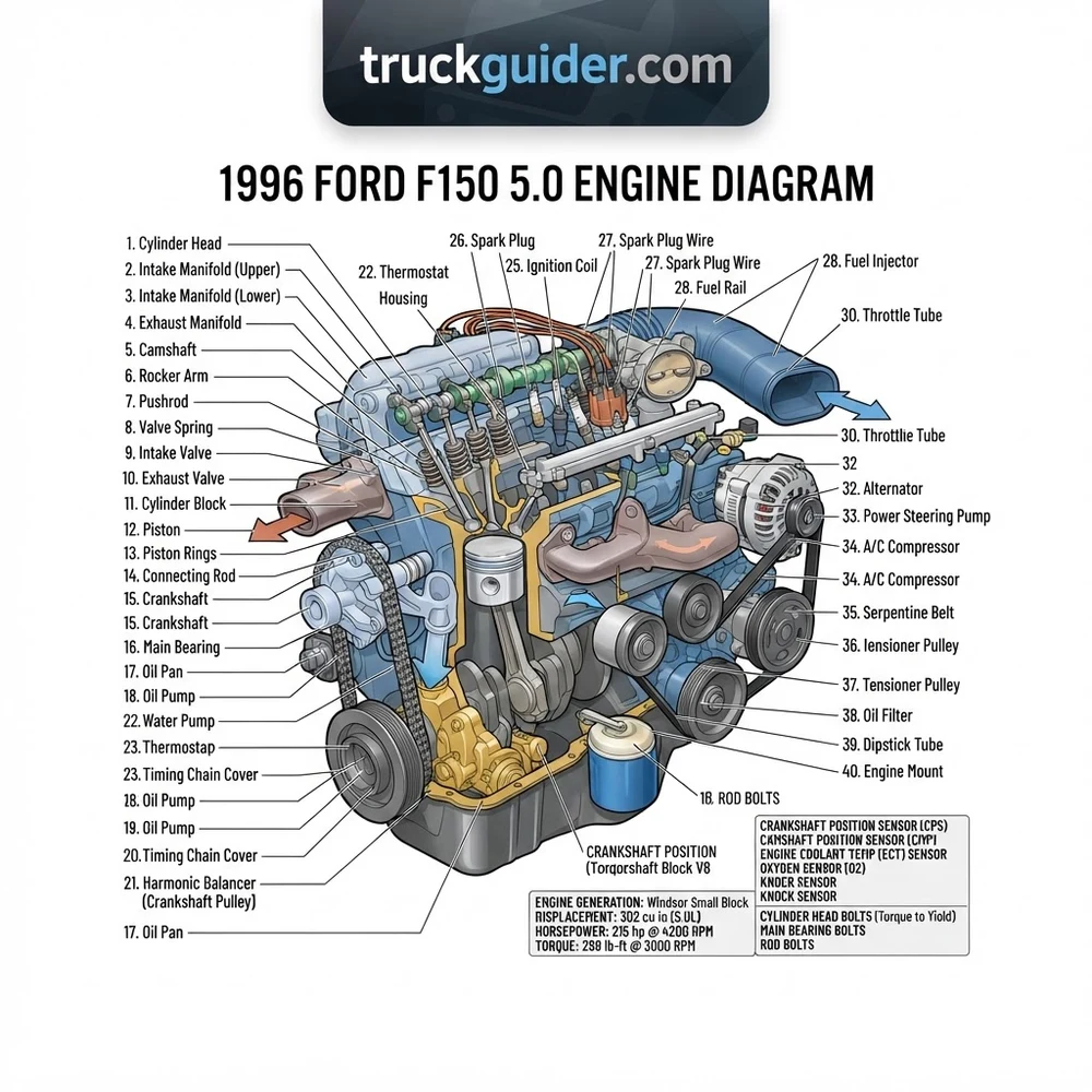
1996 Ford F150 5.0 Engine Diagram: Labeled Component Layout

Deconstructing the 1996 Ford F150 5.0 engine diagram reveals an intricate layout of intake plumbing, fuel injection rails, electrical harnesses, and thermal management hardware designed around the deep-skirt cast-iron engine block. The top of the engine is dominated by the cast-aluminum multi-port intake manifold assembly, split into distinct upper and lower plenums to optimize low-end torque delivery and airflow distribution.
Unlike earlier Speed Density trucks (1987–1993), the 1996 5.0L Windsor uses sequential electronic fuel injection (SEFI) metered by an intake-mounted Mass Air Flow (MAF) assembly. Do not interchange upper manifold gaskets or harness leads with pre-1994 configurations without consulting wiring schematics.
Upper and Lower Intake Manifold Assembly

As shown in the primary engine diagram, the intake system consists of a dual-plane lower manifold (OEM part number engineering prefix F4TE) torqued directly to the cylinder head decks, and a long-runner upper plenum chamber. The lower manifold routes coolant through front crossover passages to the thermostat housing and houses the eight EV1-style Bosch top-feed fuel injectors operating at an OEM rail pressure of 39 to 42 PSI (static with vacuum disconnected). The upper plenum bolts to the lower manifold via six Torx-40 fasteners, sealed with an upper-to-lower intake gasket. The upper intake directs incoming air through two dedicated intake runners into a common plenum chamber, tuned to enhance volumetric efficiency between 1,800 and 3,200 RPM.
Throttle Body and Idle Air Control (IAC) Valve
Mounted to the passenger-side neck of the upper intake manifold sits the twin-bore 50mm throttle body assembly. Directly integrated into the side of the throttle body casting is the Idle Air Control (IAC) valve (Motorcraft CX-1678). The EEC-V computer modulates the IAC solenoid via a pulse-width modulated (PWM) duty cycle at 12 volts to maintain closed-loop target idle (typically 675 ± 25 RPM in neutral/park). Bolted beneath the throttle body shaft is the Throttle Position Sensor (TPS), which reports throttle blade angle to the PCM through a 0.5V to 4.7V linear signal return circuit. Clean airflow entering the throttle body originates from the remote air filter box, metered precisely through the Mass Air Flow sensor.
Mass Air Flow (MAF) Sensor Architecture
The 1996 model incorporates a cylindrical 70mm cast-aluminum Mass Air Flow sensor housing positioned inline between the air filter box and the dual flexible intake hoses. Utilizing a hot-wire anemometer circuit, the MAF sensor measures incoming air mass by calculating the electrical current required to maintain a heated platinum filament at 200°C above ambient air temperature. The internal analog circuitry translates this current into a 0.0V to 5.0V direct current signal transmitted to pin 88 of the Ford EEC-V engine computer, providing instantaneous load calculation for fuel trim adjustments and spark advance mapping.


Distributor and TFI Module Configuration
Located at the front driver side of the lower intake manifold, the distributor assembly indexes directly into the engine block, driving the internal oil pump via an intermediate hexagonal hardened-steel drive shaft linked to the bottom of the distributor gear. For the 1996 model year, Ford utilized a remote-mounted Thick Film Ignition (TFI-IV / CCD) module, isolated from engine block heat soak by bolting it to an aluminum finned heat sink on the driver-side inner fender apron. The distributor internal housing contains an optical Hall-effect stator (Vane Switch / Stator PIP sensor) that sends the Profile Ignition Pickup (PIP) square-wave reference signal to the EEC-V module for ignition sequencing.
| Component | OEM Part / Engineering Ref | Key Operating Parameter |
|---|---|---|
| MAF Sensor | F5TF-12B579-AA | 0.5–4.7 V DC output curve |
| Idle Air Control Valve | F2TZ-9F715-A (CX-1678) | PWM duty cycle (6–13 Ohms resistance) |
| Ignition Stator (PIP) | F1TZ-12A112-A | 12V Hall-Effect square wave output |
| Fuel Injectors (8x) | F0TE-D5B (19 lb/hr orange top) | 11.0–14.5 Ohms coil impedance |
| Throttle Position Sensor | F4TZ-9B989-AA | 0.90–0.98V baseline idle closed |
Cylinder Head, Valve Train, and Firing Order Architecture
Understanding the mechanical valvetrain and combustion timing is essential when inspecting the 1996 Ford F150 5.0 engine diagram. Ford transitioned late 5.0L truck blocks to standard hydraulic roller camshaft configurations (cam casting casting F1TE), altering the traditional 302 Windsor firing order to match the 351 Windsor and 5.0L High Output (HO) marine/passenger configurations.
1996 5.0L Truck Firing Order: 1 – 3 – 7 – 2 – 6 – 5 – 4 – 8 (Counter-Clockwise distributor rotation). Standard 302 firing order (1-5-4-2-6-3-7-8) does NOT apply to this year and will cause severe misfire and unburnt fuel backfire.
Cylinder Numbering and Geometry
Ford engines follow a standardized cylinder numbering convention referenced directly across all engine block schematics:
- Passenger Side (Bank 1): Cylinders 1, 2, 3, 4 (Front to Rear)
- Driver Side (Bank 2): Cylinders 5, 6, 7, 8 (Front to Rear)
The cast-iron cylinder head features wedge-shaped combustion chambers (nominal volume 64cc) equipped with 1.78-inch intake valves and 1.45-inch exhaust valves. The valve train uses stamped-steel 1.6:1 ratio rocker arms secured with pedestal mounts (5/16-5/16 bolt-down assemblies torqued to 18–25 lb-ft) rather than traditional adjustable press-in studs. Hardened steel pushrods (standard length 6.272 inches) ride atop OEM link-bar hydraulic roller lifters held in place by a stamped-steel alignment retainer (“spider”) and eight dog-bone guides bolted into the lifter valley of the engine block.
Crossfire Hazard: High secondary ignition voltage can induce inductive crossfire between adjacent cylinders firing consecutively. On the 1996 5.0L, cylinders 7 and 8 sit sequentially in the firing order and alongside each other on the driver-side cylinder head deck. Keep ignition wires 7 and 8 strictly separated using OEM wire separators; do not route them parallel in the wire harness looms.



Base Ignition Timing and the SPOUT Connector
The Ford EEC-V powertrain control computer manages dynamic spark advance based on RPM, engine coolant temperature, and MAF input. However, base ignition timing must be mechanically synchronized to the crankshaft position. To set or verify base ignition timing:
- Bring the engine to normal operating temperature (coolant temp > 180°F).
- Shut down the engine and locate the SPark OUTput (SPOUT) shorting bar connector, positioned within the wiring pigtail near the remote TFI module on the driver inner fender apron.
- Disconnect the SPOUT shorting plug to break the EEC-V spark advance feedback loop. This locks timing to purely mechanical distributor output.
- Hook up an inductive timing light to the number 1 spark plug wire and read the pointer against the vibration damper (crankshaft harmonic balancer) timing marks.
- Loosen the distributor hold-down clamp bolt (1/2-inch bolt) and rotate the distributor housing until the pointer aligns precisely with 10° Before Top Dead Center (BTDC).
- Torque the distributor clamp to 17–25 lb-ft, shut off the engine, reinsert the SPOUT plug, and restart the engine. Verify that the timing mark advances immediately past 20° BTDC, indicating active computer advance control.
1996 Ford F150 5.0 Engine Diagram for Serpentine Belt Routing
The front accessory drive system on the 1996 5.0L Windsor uses a single multi-rib serpentine belt (6-rib, standard width) driven by the crankshaft pulley. Belt tension is continually regulated by an automatic spring-loaded tensioner assembly mounted between the alternator and water pump, maintaining belt grip across the water neck and high-draw accessory pulleys. The Vehicle Emission Control Information (VECI) decal on the upper radiator core support provides the factory-stamped belt routing diagram, which varies according to the presence of air conditioning equipment.
Accessory Drive Pulley Configuration
The accessory layout on the 1996 5.0L features dedicated component locations:
- Upper Passenger Side: Alternator (95-amp or optional 130-amp 3G series).
- Mid-Lower Passenger Side: Smog (Secondary Air Injection) Pump.
- Center: Reverse-rotation water pump pulley with reverse-pitch impeller, driven by the smooth backside of the serpentine belt, directly adjacent to the cast-aluminum thermostat housing and water neck.
- Upper Driver Side: Factory Sanden/FS10 A/C compressor, or an OEM idler/A/C delete bypass pulley (Motorcraft YS-269).
- Lower Driver Side: Ford C-2 hydraulic power steering pump.
- Center Bottom: Cast-iron crankshaft harmonic balancer/crankshaft pulley.
- Upper Mid-Center: Automatic spring-loaded belt tensioner with an internal calibrated wear range indicator.
Factory Serpentine Belt Routing Sequence
To install a new belt on an A/C-equipped 5.0L engine according to the front engine routing diagram:
- Path Step 1: Route the grooved side of the belt around the bottom of the crankshaft pulley.
- Path Step 2: Carry the belt upward toward the driver side, seating the grooved side into the power steering pump pulley.
- Path Step 3: Route the grooved side up and over the top of the A/C compressor clutch pulley.
- Path Step 4: Loop the smooth backside of the belt under the smooth reverse-rotation water pump pulley.
- Path Step 5: Guide the belt over to the passenger side, routing the grooved side around the bottom of the secondary air pump pulley.
- Path Step 6: Bring the belt straight up and over the top grooved alternator pulley.
- Path Step 7: Pull a 1/2-inch breaker bar clockwise on the tensioner pulley hex boss to unload internal spring tension, slipping the smooth backside of the belt under the idler/tensioner pulley, then release the breaker bar to set static tension.
OBS Ford F-150 Engine Block and Generation Coverage (1987–1996)
The 1987 to 1996 ninth-generation and late eighth-generation Ford F-150 trucks—collectively designated the “Old Body Style” (OBS) series—utilized three distinct small-block pushrod and early modular engine platforms. The 1996 model represents a technological milestone because it served as the bridge between traditional pushrod hardware and the incoming overhead-cam Ford 4.6L Modular V8 introduced in the tenth-generation 1997 F-150.


While the larger Ford 5.8L (351 Windsor) V8 shared cylinder head architecture and combustion geometry with the 5.0L, the 5.8L utilized a taller deck height (9.500 inches vs. the 5.0L’s 8.206 inches), a larger crankshaft main journal diameter (3.000 inches vs. 2.248 inches), and unique lower intake manifolds. The 1996 5.0L block uniquely integrated an external 36-1 tooth Crankshaft Position (CKP) trigger wheel bolted directly behind the crankshaft harmonic balancer, monitored by a variable reluctance sensor mounted to the front aluminum timing cover. This single-year configuration gave the Ford EEC-V engine computer misfire-monitoring compliance required by federal OBD-II mandates.
| Feature / Specification | 1987–1993 5.0L Windsor | 1994–1995 5.0L Windsor | 1996 5.0L Windsor (Final Year) |
|---|---|---|---|
| Engine Management System | EEC-IV (OBD-I, 60-pin) | EEC-IV (OBD-I, 60-pin) | EEC-V (OBD-II, 104-pin) |
| Air Metering Strategy | Speed Density (MAP sensor) | Speed Density (MAF on CA/Auto) | Mass Air Flow (Standard all states) |
| Camshaft Profile | Flat Tappet Hydraulic | Hydraulic Roller (F1TE) | Hydraulic Roller (F1TE) |
| Cylinder Firing Order | 1-5-4-2-6-3-7-8 | 1-3-7-2-6-5-4-8 | 1-3-7-2-6-5-4-8 |
| Crankshaft Sensor (CKP) | None | None | Yes (36-1 wheel on balancer) |
| Downstream O2 Sensor | None (Single upstream) | None (Single upstream) | Dual upstream + post-cat monitor |
| TFI Module Mounting | Distributor Base | Fender Well (Remote CCD) | Fender Well (Remote CCD) |
1996 Ford F150 5.0 Engine Diagram Diagnostic and Failure Points
Diagnosing driveability faults on the 1996 5.0L requires correlating schematic diagrams with proven physical failure points. Because 1996 vehicles utilize fully active OBD-II Diagnostic Trouble Codes (DTCs), mechanics can access live sensor data via the 16-pin DLC port situated beneath the driver dash panel, isolating issues across vacuum circuits, EGR controls, ignition components, and block gaskets.
DPFE and EGR Valve Assembly Malfunctions
The Exhaust Gas Recirculation (EGR) circuit on the 1996 5.0L uses a Differential Pressure Feedback EGR (DPFE) system rather than the older mechanical position sensor (EVP) found on EEC-IV systems. The DPFE sensor (Motorcraft DPFE-15) reads exhaust pressure drop across an internal metered orifice tube.
- Symptoms: Illumination of Check Engine Light with stored DTCs P0401 (Insufficient EGR Flow) or P0402 (Excessive Flow), accompanied by severe tip-in spark knock (detonation) under light load.
- Root Cause: The silicone reference hoses connecting the exhaust sample tube to the DPFE sensor soften, crack, or clog with solid carbon debris. The sensor’s internal ceramic diaphragm also suffers moisture degradation.
- Remedy: Inspect and ream the sampling tube ports with carb cleaner. Measure DPFE signal voltage at idle (OEM spec: 0.8V to 1.0V DC on the signal return wire). If voltage reads above 1.2V at idle or fails to rise smoothly to 3.5V–4.2V under commanded vacuum, replace the DPFE sensor.
Vacuum Tree and Distribution Harness Leaks
The engine uses an intricate network of color-coded semi-rigid nylon vacuum lines driven off the main multi-port vacuum tree bolted to the center plenum of the upper intake manifold.
- Symptoms: High uncommanded idle (1,100+ RPM), DTC P0171 / P0174 (System Too Lean Bank 1/Bank 2), and HVAC airflow defaulting exclusively to the defroster vents under acceleration.
- Root Cause: Thermal cycles cause the factory plastic vacuum lines to become brittle, shattering near the exhaust crossover and beneath the lower intake runners. Key failure lines include the red line (main fuel pressure regulator reference) and white line (HVAC fresh air blend door).
- Remedy: Trace vacuum lines using the under-hood vacuum schematic. Replace decayed nylon tubing with 5/32-inch high-temp silicone vacuum hose directly from the vacuum tree ports. Use an unlit propane torch or smoke machine around lower intake gasket mating lines to pinpoint gasket leakage.
Distributor Hall-Effect Stator and TFI Failures
While relocating the TFI module to the driver inner fender reduced thermal breakdowns, the internal Hall-effect PIP stator inside the distributor remains a high-frequency failure point.
- Symptoms: Sudden intermittent engine stall when warm; engine cranks continuously without spark or injector pulse until fully cold; DTC P0320 (Ignition Engine Speed Input Circuit Malfunction) stored in EEC-V memory.
- Root Cause: The internal Hall-effect sensor develops an open circuit under prolonged thermal loading, severing the square-wave PIP output required by the computer to trigger the fuel injector ground drivers and TFI spark output.
- Remedy: Probe the PIP signal wire (Dark Blue with Light Green stripe) using a digital multimeter set to Hertz or an oscilloscope while cranking. A healthy stator generates an oscillating 12V-to-ground digital square wave (approx. 20–30 Hz cranking frequency). If 12V and ground references are verified at the distributor connector but PIP output is flatlined at 0V or continuous 12V, press off the distributor drive gear and replace the internal stator assembly, or install a remanufactured distributor unit.
Lower Intake Manifold Gasket Blowouts
The lower intake manifold on the 302 Windsor seals against both cast-iron cylinder head intake decks and the engine block lifter valley end rails. The factory installation uses stamped composition gaskets alongside cork or rubber end-rail seals.
- Symptoms: Gradual loss of coolant without external puddles; oily residue pooled at the rear base of the distributor; coolant contamination inside the crankcase appearing as milky sludge beneath the oil fill cap; DTC P0300 multi-cylinder misfires.
- Root Cause: Corrosion along the aluminum lower intake coolant passages eats away the paper sealing barriers surrounding the cylinder 1 and cylinder 5 water jackets. Additionally, the rubber front and rear lifter valley cork strips blow outward under crankcase pressure.
- Remedy: Remove the upper and lower intake manifolds. Discard replacement cork end seals; install heavy-duty steel-core laminate intake gaskets (e.g., Fel-Pro MS90103-1) with a continuous 5/16-inch bead of RTV silicone sealant across the front and rear lifter valley walls, overlapping onto the cylinder head deck corners. Torque the lower intake manifold bolts in three progressive steps (step 1: 8 lb-ft, step 2: 15 lb-ft, final step: 23–25 lb-ft) following the OEM crisscross pattern starting from the center inner bolts working outward.
1996 Ford F150 5.0 Engine Technical FAQs
What is the correct spark plug gap and torque specification for the 1996 5.0L F-150?
The factory-specified spark plug is the Motorcraft ASF-42C (standard copper core) or equivalent. Set the electrode gap precisely to 0.042–0.046 inches (1.07–1.17 mm). Apply a light drop of anti-seize compound to the 14mm threads and torque each plug into the cast-iron cylinder head to 15–20 lb-ft (20–27 Nm). Over-tightening can gall threads or distort the combustion shell seat.
How do I differentiate a 1996 5.0L engine block from earlier 1987–1993 302 blocks?
Inspect the lower right-hand side of the engine block directly above the oil pan rail near the starter mount for the cast engineering number. The 1996 roller block displays casting code F4TE-6015-AA. Additionally, verify the presence of threaded bosses cast into the center valley for the factory roller lifter spider tray, and examine the front crankshaft nose for the integrated 36-1 tooth reluctor ring utilized by the EEC-V Crankshaft Position sensor.
Why does my 1996 F-150 5.0 run poorly after a standard distributor cap replacement?
The most common error is cross-referencing an obsolete 302 firing order. The 1996 5.0L truck engine strictly utilizes the 351W/HO firing order: 1-3-7-2-6-5-4-8 with counter-clockwise distributor rotor rotation. If spark plug leads are routed according to the older standard 302 firing order (1-5-4-2-6-3-7-8), four out of eight cylinders fire out of phase, producing violent backfires, black exhaust smoke, and an immediate check engine light.
What is the standard oil pressure spec for the 1996 5.0L Windsor V8?
According to factory specifications, normal warm operating oil pressure should register between 40 and 60 PSI at 2,000 RPM using SAE 10W-30 or 5W-30 engine oil. Minimum allowable hot idle pressure is 15 PSI. If a mechanical pressure test gauge connected to the 1/4-inch NPT oil filter adapter port indicates less than 15 PSI at warm idle, inspect for worn camshaft bearings, excessive crankshaft rod journal clearance, or a clogged oil pump pick-up tube screen inside the deep-sump oil pan.
Where is the OBD-II diagnostic port located on the 1996 F-150 5.0L?
As an official OBD-II compliant platform, the 1996 F-150 houses a standardized 16-pin Data Link Connector (DLC) under the driver-side dashboard, positioned between the steering column and the emergency brake release lever. It does not utilize the two-piece EEC-IV diagnostic test pigtails located near the under-hood passenger fender apron found on 1987–1995 OBS trucks.
Step-by-Step Guide to Understanding the 1996 Ford F150 5.0 Engine Diagram
1Identify – Verify the ‘N’ engine code on the vehicle VIN plate to confirm the 5.0L 302 Windsor platform.
2Locate – Find the primary timing indicators on the crankshaft harmonic balancer and the distributor rotor position for cylinder number one.
3Reference – Consult the diagram to align the camshaft timing sprocket dot directly with the crankshaft timing sprocket mark at 12 and 6 o’clock positions.
4Torque – Fasten each connecting rod cap nut to 21–25 lb-ft and progressively torque the cylinder head bolts in sequence up to 65–72 lb-ft.
5Verify – Check valve train preload on the hydraulic roller lifters and manually rotate the crankshaft two full revolutions to ensure zero mechanical interference.
6Troubleshoot – If low oil pressure or valve train noise persists, inspect the oil pump intermediate shaft engagement and verify pushrod straightness.
Author