1997 GMC Sierra Fuse Box Diagram: 2026 Repair Guide

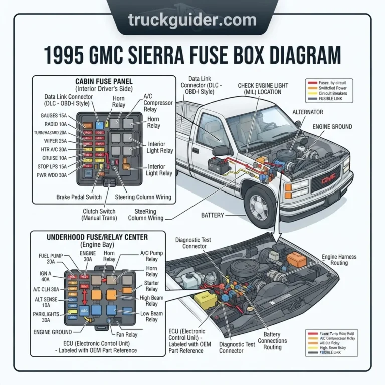
The 1997 GMC Sierra features two primary fuse blocks: the interior instrument panel fuse box located behind the driver-side dashboard trim panel, and the underhood electrical center mounted near the brake master cylinder. Check the 20A ‘ECM B’ and 15A ‘ECM I’ fuses for ECU and fuel delivery power issues.
📌 Key Takeaways
- The underhood electrical center houses high-amperage Maxi-fuses (30A–50A) and system relays for the fuel pump, starter, and ignition.
- The interior dash fuse block controls auxiliary circuits, lighting, and the 15A Cigarette Lighter fuse powering the OBD-II diagnostic port.
- Always disconnect the negative battery cable; battery terminal bolts require a torque spec of 11 ft-lbs (15 Nm) during reinstallation.
- Thermal stress on the fuel pump relay and oxidation within the engine-bay fuse socket contacts are frequent failure points.
- Simple fuse and relay swaps are safe for DIYers; persistent short circuits triggering an ECU diagnostic code warrant professional electrical diagnosis.
The 1997 GMC Sierra 1500, 2500, and 3500 platform (GMT400 chassis) utilizes a split-bus electrical architecture split across two primary power distribution points: the Instrument Panel (I/P) Fuse Block located inside the cab and the Underhood Electrical Center (UEC) situated within the engine bay. Managing transient spikes, inductive relay kickback, and direct battery feeds across Vortec gasoline and Detroit Diesel powertrains requires an exacting understanding of these junction points. Whether you are tracking a no-communication error at the diagnostic data link connector, tracing an intermittent ignition drop-out, or isolating an ignition-off parasitic draw, this technical documentation delivers the complete wiring schematics, amperage ratings, and circuit traces for the factory electrical system.


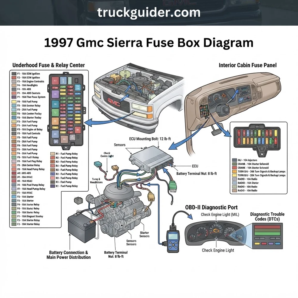
Figure 1: Schematic mapping of power flow from 12V BATT through the Underhood Electrical Center down to the cabin Instrument Panel Fuse Block.
1997 GMC Sierra Fuse Box Diagram and Component Locations

The 1997 GMC Sierra utilizes a two-tier protection strategy separating high-current chassis circuits from low-draw interior accessories. To service or trace these buses, you must establish physical orientation at both the Instrument Panel (I/P) Fuse Block and the engine bay Underhood Electrical Center.
The Instrument Panel Fuse Block is concealed behind an integrated structural cover on the driver-side edge of the dashboard. Access requires opening the driver door completely and releasing the trim retaining clip with a flat pry tool or hand pressure. This block houses standard mini and fast-acting ATO/ATC blade fuses ranging from 5A to 30A, along with solid-state auto-reset circuit breakers designed for intermittent high-load motors (such as power window regulators and power seats).
On GMT400 trucks showing intermittent cabin electrical outages, confirm the structural integrity of the plastic hinge tabs on the dashboard access door. Worn tabs allow the cover panel to press directly against the faces of ATO fuses, causing mechanical fatigue and terminal fretting over rough terrain.
Directly beneath the dashboard to the left of the steering column lies the auxiliary convenience center connector bus, tying into your ignition switch harness replacement routines and master relay feeds. Meanwhile, primary high-amp current distribution is isolated under the hood.
The Underhood Electrical Center is mounted directly to the driver-side inner fender sheet metal, positioned aft of the battery and forward of the brake master cylinder vacuum booster. This plastic housing features a weather-sealed lift-off lid secured by two heavy-duty locking tabs. The underhood center directs raw amperage originating at the positive battery terminal and starter junction post, stepping down power via Maxi-fuses before routing it to the dash fuse box and engine management subsystems.
| Position | Amperage | Fuse Type | Protected Systems & Circuit Logic |
|---|---|---|---|
| 1 | 20A | ATO/ATC | Stop/Hazard Lamps, Hazard Flasher, High-Mount Stop Lamp (CHMSL) |
| 2 | 5A | Mini | Instrument Cluster Keep-Alive Memory, PRNDL Display Logic |
| 3 | 25A | ATO/ATC | Headlamp Relay, High/Low Beam Dimmer Switch Interface |
| 4 | 10A | Mini | Gauges, Warning Lamps, Check Engine Light (MIL), Rear Defog Timer |
| 5 | — | — | Unpopulated / Spare Cavity |
| 6 | — | — | Unpopulated / Spare Cavity |
| 7 | — | — | Unpopulated / Spare Cavity |
| 8 | 20A | ATO/ATC | Crank Signal to VCM/PCM, Neutral Safety / Park-Neutral Switch |
| 9 | 25A | ATO/ATC | Windshield Wiper Motor Run/Pulse Board, Washer Pump Solenoid |
| 10 | — | — | Unpopulated / Spare Cavity |
| 11 | — | — | Unpopulated / Spare Cavity |
| 12 | — | — | Unpopulated / Spare Cavity |
| 13 | 20A | ATO/ATC | Cigarette Lighter, DLC Pin 16 (OBD-II 12V B+ Unswitched Feed) |
| 14 | — | — | Unpopulated / Spare Cavity |
| 15 | 10A | Mini | HVAC Control Head, A/C Low Pressure Cutoff Switch Logic |
| 16 | — | — | Unpopulated / Spare Cavity |
| 17 | — | — | Unpopulated / Spare Cavity |
| 18 | — | — | Unpopulated / Spare Cavity |
| 19 | 25A | ATO/ATC | Turn Signal Flasher, Back-up Lamps, Manual Shift Interlock |
| 20 | 10A | Mini | 4WD Transfer Case Switch, Shift-on-the-Fly Actuator, 4L60E/4L80E VCM Run Feed |
| CB-1 | 30A | Breaker | Power Windows, Power Sunroof Assembly |
| CB-2 | 30A | Breaker | Power Door Locks, 6-Way Power Lumbar/Bucket Adjusters |
Underhood Electrical Center Circuits and Maxi-Fuse Ratings

The Underhood Electrical Center (UEC) acts as the bridge between alternator output and sensitive control computers. Utilizing high-capacity Maxi-fuses (measuring 29.2 mm terminal-to-terminal), this panel shields heavy amperage circuits while isolating high current draws away from the cabin. It also houses standard 5-pin ISO micro and mini relays controlling the fuel system, air conditioning clutch, and secondary ignition coils.
Wiring topologies in the 1997 Sierra shift significantly based on powertrain fitment. Vortec gasoline engines (4.3L L35 V6, 5.0L L30 V8, 5.7L L31 V8, and the big-block 7.4L L29 V8) rely heavily on the ECM-B and ENG-I lines. ECM-B delivers battery positive voltage to the fuel pump relay coil and internal Vehicle Control Module (VCM/ECU) memory circuits. ENG-I supplies unswitched battery voltage through the ignition relay to fuel injection poppets, exhaust gas oxygen (O2) sensor heater elements, and the electronic ignition coil control module.


Conversely, the 6.5L Detroit Diesel (L56 and heavy-duty L65 platforms) replaces the spark delivery circuits with an ultra-high-draw glow plug relay requiring dedicated protection up to 60A. The diesel configuration also repurposes the ECM lines to energize the Pump Mounted Driver (PMD/FSD) and the fuel shut-off solenoid integrated into the Stanadyne DS4 electronic injection pump.
| Fuse/Relay ID | Rating | Wire Gauge / Color | Vortec Gas (4.3L, 5.0L, 5.7L, 7.4L) | Detroit Diesel (6.5L Turbo L65) |
|---|---|---|---|---|
| IGN-A | 50A Maxi | 10 AWG Red | Ignition Switch (BATT feed to dash) | Ignition Switch / Dual Battery Buffer |
| IGN-B | 50A Maxi | 10 AWG Red/Wht | Starter Relay, I/P Fuse Block Bat Bus | Glow Plug Relay Feed, Starter Relay |
| ECM-B | 20A Mini | 14 AWG Org | Fuel Pump Relay & VCM Constant 12V | Lift Pump Relay & PMD Main Logic |
| ENG-I | 20A Mini | 14 AWG Pnk | O2 Sensors, Cam/Crank Sensors, EVAP | Wastegate Solenoid, Fuel Shutoff Valve |
| ABS | 60A Maxi | 8 AWG Red | Kelsey-Hayes 4-Wheel ABS Modulator | Kelsey-Hayes ABS Modulator Pump |
| A/C RELAY | ISO Relay | 16 AWG Dk Grn | Compressor Clutch Magneto | Compressor Clutch (High Idle Logic) |
| FP RELAY | ISO Relay | 14 AWG Gry | In-tank High-Pressure Pump (60 psi) | Frame-rail Low-Pressure Lift Pump (7 psi) |
Never swap the 20A ECM-B fuse with higher-rated 25A or 30A fuses to stop intermittent popping. The fuel pump circuit runs inside the primary harness along the driver-side frame rail. Oversizing this fuse can cause insulation melt-down and severe fire hazards before thermal trip thresholds are reached.
1997 GMC Sierra Fuse Box Symptoms: Dead OBD-II and Fuel Pumps
When electrical failures strike a GMT400 truck, they typically center around specific, recurring failure points. If your engine cranks but will not fire, or your handheld diagnostic scan tool reports zero bus communication, use the following triage steps to isolate the issue directly at the fuse blocks:
- No Communication with Diagnostic Scanner (Dead OBD-II Port): The primary culprit is a blown Fuse 13 (20A Cigarette Lighter) inside the cab I/P fuse block. Pin 16 of the On-Board Diagnostics (OBD-II) Data Link Connector (DLC) draws unswitched battery voltage (B+) directly from this exact circuit via a 16 AWG orange wire. If an aftermarket phone charger or accessory grounded the lighter socket shell, Fuse 13 opens. The diagnostic scanner cannot boot or communicate with the ECU, leaving technicians unable to pull any stored diagnostic code.
- Long Cranking Before Starting (Delayed Fuel Prime): A failing or blown fuel pump relay in the Underhood Electrical Center does not fully disable the truck. General Motors engineered an analog fail-safe through the three-terminal engine oil pressure sending unit switch. When cranking reaches enough engine speed to build 4 to 5 psi of oil pressure, an internal mechanical diaphragm closes contacts on a secondary 12V bypass line (Circuit 120, Orange/Gray wire). This feeds direct battery voltage to the fuel pump. If your Sierra requires 7 to 10 seconds of constant cranking before catching, the underhood fuel pump relay or its socket terminal pin 87 has open circuit continuity, forcing the truck to rely strictly on oil pressure build-up.
- Illuminated Check Engine Light with Oxygen Sensor Codes: Simultaneous trouble codes P0135, P0141, P0155, and P0161 (indicating failed O2 sensor heater elements on all banks) almost never point to bad sensors. Check the underhood ENG-I (20A) fuse. If this single fuse blows—often caused by a harness rubbing against the front driveshaft or exhaust y-pipe—all O2 heater banks lose power instantly, triggering a persistent check engine light.
- Intermittent Instrument Cluster Drop-Out (Gauges Die at Speed): If the speedometer, tachometer, coolant temperature, and fuel level needles drop to zero simultaneously while driving, inspect Fuse 4 (10A GAUGES) in the cab panel. Terminal fretting on the input side of this mini-fuse or a micro-fractured fuse element causes open-circuit conditions under specific vehicle vibration harmonics. This cuts the switched ignition input feed to cluster logic modules.
- Inoperative Variable Orifice Steering or Front 4WD Engagement: If your 4×4 floor shifter or pushbutton assembly fails to command the front differential thermal/electro-actuator, inspect Fuse 20 (10A TRANS) in the cabin box. Without this switched 12V ignition trigger, the front axle cannot lock, and the transfer case control module drops offline.
Diagnosing Blown Fuses and ECU Circuit Faults Step by Step
Diagnosing intermittent shorts, voltage drops, and open circuits on an aging 1997 platform requires an organized approach using a True-RMS digital multimeter (DMM), terminal load spoons, and schematic continuity maps. Follow these steps to resolve challenging circuit faults:
- Perform In-Situ Voltage Drop Tests across Blade Terminals: Set your multimeter to DC Millivolts (mV). Do not extract every fuse to visually inspect the filament—pulling fuses unseats terminal tension and can temporarily clear mechanical contact shorts. Place your fine-point DMM probes directly into the two exposed metal test points on the back of each blade fuse with the vehicle in “Key-On, Engine-Off” (KOEO) mode. Any measurable millivolt drop (typically greater than 0.5 mV to 10.0 mV depending on circuit draw) confirms closed-circuit current flow. A reading of 0.0 mV indicates either no current draw or an open circuit. If one test point measures battery voltage (approx. 12.6V) and the other measures 0.0V, the fuse is blown open.
- Isolate Dead Shorts to Ground without Wasting Fuses: If a fuse blows instantly upon insertion, never replace it repeatedly. Remove the blown fuse and connect an automotive halogen test light (or a dedicated resetting circuit breaker) across the load and supply terminals inside the socket cavity. If a short to ground exists downstream on that circuit, the bulb will glow at full brightness as current flows directly to ground. Systematically disconnect sub-harnesses, sensors, and actuator pigtails along the loom. When the test light dims significantly or extinguishes completely, you have pinpointed the exact branch containing the wire-to-chassis short.
- Measure Ignition-Off Parasitic Battery Drain: GMT400 trucks frequently experience drained batteries after sitting 48 to 72 hours. To isolate this draw:
- Ensure all cab doors are shut or latch switches are mechanically depressed using tape or clamps.
- Disconnect the negative battery side-terminal cable.
- Place your multimeter in DC Amps mode (starting on the 10A fused scale) in series between the battery’s negative lead pad and the disconnected terminal end.
- Wait 15 to 20 minutes for factory computer modules to enter low-power sleep mode. Normal steady-state parasitic draw must rest below 50 mA (0.050 Amps).
- If the draw exceeds 100 mA, pull fuses one at a time from the cab fuse block while watching your DMM screen. The moment the draw drops to nominal spec, you have identified the offending circuit branch (often related to the factory radio amplifier, illuminated vanity mirrors, or an aftermarket security system).
- Verify Fusible Link Integrity at the Firewall and Starter: High-amperage current leaving the starter solenoid travels through four color-coded fusible links before reaching the Underhood Electrical Center. If the entire truck is electrically dead despite a healthy battery showing 12.6V, grip the inline fusible link wires located on the terminal studs. Gently pull along their length; if the rubber insulation stretches like an elastic band, the internal wire conductor has melted open under excessive load. Replace damaged sections using only factory-grade hypalon wire sized four AWG gauges smaller than the wire run it protects.
- Validate Engine Control Module (VCM/ECU) Power Feeds: When tracking an engine crank-no-start condition accompanied by a missing fuel pump prime pulse, measure the primary inputs directly at the VCM. The VCM on a 1997 Sierra is mounted under the hood behind the air cleaner box on the driver side. Test for stable battery positive voltage on the continuous feed (Circuit 740, Orange wire) and switched ignition feed (Circuit 439, Pink wire). Both terminals must maintain minimum battery voltage during initial key crank cycles. If voltage collapses below 9.6V under starter draw, perform ground strap restoration across the engine-to-chassis bond wire and recondition your vehicle’s frame ear grounding points.
When servicing GM side-terminal battery posts or mounting junction distribution blocks, use these exact manufacturer torque specs:
• Battery Side-Terminal Bolts: 11 Nm (97 lb-in / 8.1 lb-ft)
• Underhood Electrical Center Power Stud Nut: 10 Nm (89 lb-in / 7.4 lb-ft)
• Alternator Output B+ Terminal Nut: 9 Nm (80 lb-in / 6.6 lb-ft)
Over-torquing side-terminal lead threads strips the battery casing, creating high-resistance hot spots that cause erratic system voltage spikes.
Confirm the structural health of your charging network by reviewing our complete guide to alternator charging circuit diagnostics, especially if the high-amp 50A Maxi-fuses show signs of thermal fatigue or melting at their base blades without popping the central filament element.


1997 GMC Sierra Fuse Box Diagram Frequently Asked Questions
Which fuse controls the OBD-II diagnostic port and scanner interface on a 1997 Sierra?
Pin 16 of the onboard diagnostic DLC is powered exclusively by Fuse 13 (20A CIGAR) located inside the cab’s Instrument Panel Fuse Block. If this fuse blows from a short inside the accessory lighter socket or phone charger, scan tools will fail to power up or read diagnostic trouble codes. Replacing this 20A ATO blade fuse restores power across the scan tool connection.
Why does my fuel pump keep running even if the underhood fuel pump relay fails?
The 1997 GMC Sierra uses an analog redundant circuit built into the oil pressure sending unit switch. When the engine cranks or runs and engine oil pressure rises above 4 psi, an internal switch contact closes. This connects direct battery power to the fuel pump along Circuit 120. If your engine cranks longer than normal before starting, your fuel pump relay has likely failed, forcing the pump to wait until mechanical oil pressure builds up to energize the circuit.
Where is the main ECU / VCM fuse located on the 1997 GMC Sierra?
Engine management power relies on two separate fuses within the Underhood Electrical Center (UEC). The ECM-B (20A) fuse supplies continuous, unswitched battery positive voltage for computer memory circuits and the fuel pump relay coil. The ENG-I (20A) fuse powers engine sensors, the ignition control module, and the oxygen sensor heater circuits once the ignition key turns to the Run position.
How do I differentiate a blown fusible link from a failed Maxi-fuse?
A Maxi-fuse features a clear or tinted polycarbonate housing with a visible center element that melts and severs under load. Fusible links, found along wiring junctions near the starter solenoid, look like standard wire segments with thicker insulation. A failed fusible link feels soft, spongy, or stretches under tension because the internal metal conductor has melted away while leaving the external fire-resistant hypalon sleeve intact.
Can low engine coolant or a stuck thermostat blow an electrical fuse?
Low coolant levels or improper coolant flow do not directly blow electrical fuses. However, extreme engine bay temperatures from severe overheating can soften harness insulation along the block and exhaust manifolds. This causes wires to melt through, generating direct chassis shorts on the ENG-I or O2 sensor circuits that blow your underhood fuses. Keep wiring harnesses properly secured away from heat sources to avoid thermal damage.
Step-by-Step Guide to Understanding the 1997 Gmc Sierra Fuse Box Diagram
Identify – Note the failing electrical system (e.g., fuel pump, headlights, ECU) to pinpoint the matching fuse number on the schematic.
Locate – Remove the interior dashboard side cover or unlatch the underhood electrical center cover near the driver-side fender.


Reference – Match the diagram layout directly to the socket positions, verifying the exact fuse or relay slot and rated amperage.
Connect/Route – Extract suspect fuses using a fuse puller and install a verified, identically rated blade fuse into the terminal clips.
Verify – Turn the ignition key on and check for circuit restoration, confirming the check engine light cycles normally without tripping fault codes.
Troubleshoot – If replacement fuses blow immediately, connect a digital multimeter to trace underlying wiring shorts or verify the 11 ft-lbs torque spec on main power studs.