1998 Chevy Silverado Ignition Switch Wiring Diagram: 2026 Repair

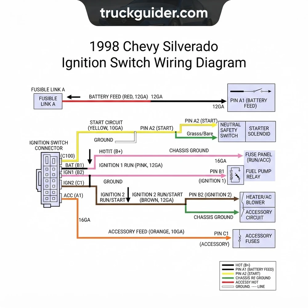
The 1998 Chevy Silverado ignition switch connects along the steering column harness. Main feeds include two constant 12V red hot wire circuits, a pink ignition 1 wire, an orange accessory feed, a yellow starter crank signal wire, and a brown ignition 2 wire. Ground wire connections tie into the dash frame chassis ground.
📌 Key Takeaways
- Dual 12V battery feeds utilize 10-12 AWG red wires protected by high-amperage underhood MaxiFuses
- Pink wire provides critical 12V power to the powertrain control module (PCM) in Run and Start positions
- Torque steering column shroud and harness retaining screws to 35 in-lbs to avoid wire pinch failures
- Burnt terminal pins on the orange accessory and brown ignition lines represent the leading failure point
- DIY repairs suit harness replacement; professional diagnosis is recommended if Passlock security triggers lockouts
Navigating the electrical infrastructure of a late-production GMT400 platform truck requires a clear grasp of current distribution and circuit logic. The 1998 Chevrolet Silverado utilizes a heavy-duty, multi-circuit ignition switch mounted on the lower steering column, driven mechanically by an actuator rod linked to the key cylinder. Because this switch routes un-fused and high-amperage fused battery power directly to critical sub-systems—including the powertrain control module, starter solenoid, and accessory relays—a single failed contact or high-resistance wire terminal can cause intermittent stalling, no-crank conditions, or dead instrument clusters. This guide provides the complete 1998 chevy silverado ignition switch wiring diagram specifications, pinouts, wire color codes, and diagnostic steps required to service the system correctly.



Understanding the 1998 Chevy Silverado Ignition Switch Wiring Diagram Architecture

The electrical architecture of the 1998 Chevrolet Silverado ignition switch wiring system marks the culmination of General Motors’ GMT400 platform engineering. Unlike contemporary computer-switched networks that rely on micro-current logic signals sent to body control modules, the 1998 C/K series trucks direct heavy current through mechanical switch contacts in the steering column. Current originates at the underhood fuse and relay center, where high-capacity fusible links and MAXI fuses (typically rated between 40A and 50A) protect the primary power feeds. From this engine compartment junction, thick-gauge battery conductors route down through the firewall bulkhead connector to the main terminal block located beneath the instrument panel.
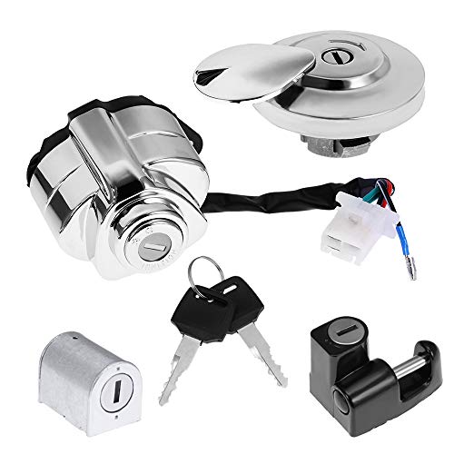
The physical ignition system divides into two operational components: the mechanical ignition lock cylinder positioned at the top right of the steering column casting, and the electrical ignition switch mounted lower down on the column jacket. Turning the key rotates an internal sector gear inside the lock housing, driving a cast-metal actuator rack and rod assembly downward. This linear rod interfaces with the slider mechanism inside the electrical ignition switch, driving internal copper leaf contacts across multiple circuit traces simultaneously.
As detailed in the 1998 chevy silverado ignition switch wiring diagram schematic, this single slider mechanism orchestrates power delivery across five key positions: ACCESSORY, LOCK, OFF, RUN, and CRANK. The switch does not simply supply power in an on/off fashion; it distributes battery potential sequentially. In the RUN position, power routes independently to the primary ignition systems (fuel injection, ignition coil, and transmission solenoids) while energizing secondary circuits for climate control and auxiliary electronics. During the transition to CRANK, the switch disconnects high-draw accessory circuits to preserve maximum terminal voltage for the starter motor while maintaining uninterrupted system voltage to the vehicle control module (VCM/PCM).
Compounding this mechanical layout is the Passlock II security integration. While the high-amperage electrical ignition switch handles the heavy operational currents, the lock cylinder housing incorporates a dedicated anti-theft sensor. Isolating these two functions is essential: electrical failures such as burned contacts, melted harness terminals, or dropped accessory feeds originate inside the lower column electrical switch, whereas no-start conditions involving an engine that fires for two seconds and dies typically stem from the Passlock sensor circuit.
1998 Silverado Ignition Switch Wire Color Code and Pin Assignment Breakdown

Connecting the electrical ignition switch to the truck’s main cab wiring harness is a high-density, multi-cavity harness connector (frequently referenced in factory service manuals as harness connector C201 or C202). Due to the electrical loads traversing this junction, GM used wire gauges ranging from 18 AWG up to 10 AWG. Technicians must pay close attention to terminal identification, as cross-connecting an accessory output with an engine management circuit can overload secondary circuits or starve the PCM of operating voltage during cranking.
| Terminal Pin | Wire Color Code | Wire Gauge | Circuit Name / Function | Operational Voltage & State |
|---|---|---|---|---|
| A | Red | 12 AWG | Main Battery Feed Wire 1 (B+) | Constant 12V Hot at all times via Underhood Fuse Block |
| B | Red | 10 AWG | Main Battery Feed Wire 2 (B+) | Constant 12V Hot at all times; supplies high-draw bus |
| C | Pink | 12 AWG | Ignition 1 (Run/Crank) Feed | 12V in RUN and CRANK; powers VCM, injectors, ignition |
| D | White | 14 AWG | Ignition 0 (Instrument / Cluster) | 12V in RUN and CRANK; diagnostic & dash feed |
| E | Orange | 12 AWG | Accessory Feed (Primary) | 12V in ACCESSORY and RUN; drops to 0V in CRANK |
| F | Brown | 12 AWG | Accessory Feed (Secondary / HVAC) | 12V in RUN only; drops to 0V in CRANK (blower cutout) |
| G | Yellow | 12 AWG | Crank / Start Output Wire | 12V in CRANK only; feeds Park/Neutral or Clutch Switch |
| P1 | Yellow | 20 AWG | Passlock II Sensor Data Signal | Variable resistance reference voltage (approx. 0.9V – 4.5V) |
| P2 | Black or Orange/Black | 20 AWG | Passlock Sensor Ground Wire | Direct chassis reference ground (continuity < 0.5 ohms) |
| P3 | White/Black | 20 AWG | Passlock 5V Reference / Power | Regulated 5.0V input from instrument cluster or VCM |
When studying the terminal block, note that the two Red wires are direct, un-fused feeds coming from separate fuses inside the underhood electrical center. The 10 AWG Red conductor powers the high-load accessory buses, while the 12 AWG Red conductor feeds the primary ignition circuits. The heavy Yellow wire carries battery voltage only when the switch slider is pushed fully forward into the CRANK position. From the switch, this wire runs down to the transmission-mounted neutral safety switch on 4L60E/4L80E automatic models, or the clutch start switch on manual transmissions, before continuing to the coil side of the starter relay.
According to OEM service specifications, the primary high-amp circuit conductors must show less than 0.2V total drop across the switch terminals under an active 15A load. Terminal pin tension in the steering column wiring harness connector must maintain a minimum retention force of 3.5 Newtons to prevent thermal degradation.
Wiring a 1998 Chevy Silverado Ignition Switch Replacement Step by Step
Replacing and re-wiring the electrical ignition switch requires mechanical disassembly of the lower dash panel and careful alignment with the lock cylinder linkage. Follow this procedural workflow to avoid damaging sensitive electrical circuits or deploying the Supplemental Inflatable Restraint (SIR) airbag system.


- Disconnect Electrical Power and Deplete Capacitors: Disconnect the negative battery cable with a 5/16-inch wrench. Wait a minimum of 10 minutes to allow the airbag module backup power supply to discharge fully. Remove the 15A “AIR BAG” fuse from the interior fuse block as an added safeguard against accidental deployment.
- Remove Lower Trim and Knee Bolster: Use a 7mm nut driver and a trim removal tool to unfasten the lower instrument panel steering column cover, the knee bolster panel, and the stamped-steel reinforcement bracket. This exposes the lower column casing and the main steering column wiring harness connector.
- Access the Electrical Ignition Switch: Locate the electrical switch assembly bolted to the top or side of the column jacket (depending on whether the column is fixed or tilt). Detach the wire harness harness retainers securing the thick loom to the column mast jacket.
- Release the Harness Connector: The heavy-gauge harness is secured by an integrated center bolt (usually 7mm) or heavy-duty snap locks on the terminal block. Back out the center bolt and disengage the harness connector housing from the switch body. Check the plastic connector shell for thermal distortion or melted pin cavities around terminals A, B, and G.
- Unbolt and Disengage the Switch Assembly: Remove the two inverted Torx (E-4 or E-5) or small hex-head mounting screws anchoring the switch body to the steering column bracket. Gently lift the switch upward to unhook the mechanical slider from the ignition switch actuator rod running from the lock cylinder.
- Prep and Align the New Switch: Before installation, confirm the replacement switch slider is indexed to the correct position (most replacement units ship pre-pinned in the OFF-UNLOCKED detent). Move the key lock cylinder to the matching position so the mechanical rod seats directly into the switch slider receiver without binding.
- Torque Fasteners and Reconnect Harness: Secure the replacement switch using the factory mounting screws, torquing them to 45 lb-in (5 Nm). Mate the steering column wiring harness connector square to the switch receptacle, tightening the center retaining bolt to 27 lb-in (3 Nm) until the locking ears seat firmly. Avoid over-tightening, which can crack the plastic terminal block.
- Validate Mechanical Range: Before reinstalling panels, reconnect the battery. Rotate the ignition key through ACCESSORY, OFF, RUN, and CRANK detents. Verify the key smoothly returns from CRANK to RUN via internal spring pressure without hanging or binding the rod mechanism.
Never attempt to force the electrical switch slider into place with the mounting screws. If the switch does not seat flush against the column bracket, the actuator rod is misaligned with the internal slider pocket. Forcing the fasteners will shear the plastic slider rack, permanently ruining the internal contact timing.
Passlock II Sensor Wiring, Voltage Resistance, and Key Relearn Procedures
A frequent complication when servicing a 1998 Silverado ignition circuit is the GM Passlock II theft-deterrent system. The Passlock sensor is an electronic Hall effect module integrated directly into the ignition lock cylinder housing, not the high-amp lower electrical switch. When the cylinder is turned with a key, a magnet embedded in the lock cylinder passes across the Hall effect sensor. This sensor draws a specific reference current and introduces a precision resistance value—often called the “R-Code”—across the Passlock Data circuit to the Vehicle Control Module (VCM).
The Passlock circuit uses three small-gauge wires (typically 20 AWG) running in a separate, thin harness down the column:
- Passlock Reference Voltage (White/Black): Delivers a regulated 5.0V reference potential directly from the instrument cluster or PCM/VCM.
- Passlock Ground (Black or Orange/Black): Provides an isolated sensor ground wire connection with near-zero resistance to ground.
- Passlock Sensor Data (Yellow): Returns the modified voltage divider signal back to the anti-theft module logic circuit.
If you replace the ignition lock cylinder, install an aftermarket universal ignition switch, or alter the wiring harness resistance, the VCM will read an unrecognized voltage code. The truck will start, run for roughly two seconds, and abruptly die as the VCM cuts off pulse commands to the fuel injectors while flashing the “SECURITY” indicator on the dashboard. To re-synchronize the modules, execute the standard GM 30-Minute Relearn sequence:
- Ensure the vehicle battery is fully charged. Connect an external battery maintainer, as the headlamps and ignition circuits will draw significant current for over half an hour.
- Turn the ignition key to the ON/RUN position (do not crank the starter). The instrument cluster SECURITY light will illuminate steadily.
- Leave the key in the ON/RUN position for exactly 10 to 11 minutes. Do not touch pedals or accessories. After approximately 10 minutes, the SECURITY light will stop flashing and turn off or stay solid.
- Turn the key to the OFF position for at least 10 seconds.
- Repeat Steps 2 through 4 two more times, for a total of three consecutive 10-minute cycles (30 minutes cumulative).
- Following the third cycle, turn the key OFF for 15 seconds. Then turn the key to CRANK to start the engine. The VCM will memorize the active Hall effect R-code voltage signal, clearing the fuel disable command.
If installing remote start systems or eliminating Passlock issues, technicians often wire a fixed metal-film resistor across the Yellow sensor wire and the Black ground wire. The resistor value must precisely match the measured R-code voltage drop of the original lock cylinder to prevent module lockouts.
Diagnosing 1998 Chevy Silverado Ignition Switch Wiring and Voltage Drop Issues
Diagnosing erratic electrical problems on 1998 Silverado trucks requires testing the ignition switch under electrical load rather than with simple continuity checks. A worn leaf contact inside the switch can show 12 volts on a digital multimeter (which draws negligible current), yet completely drop voltage when asked to pass 10 to 20 amperes to the fuel pump or heater blower.
Performing Dynamic Voltage Drop Testing
To pinpoint internal switch contact degradation, perform a dynamic voltage drop test across the switch terminals while the vehicle systems are active:
- Connect the positive lead of your digital multimeter to the un-fused Red battery feed wire (Terminal A or B) at the back of the harness connector.
- Connect the negative multimeter lead to the corresponding output wire (for example, the Pink wire at Terminal C for Ignition 1).
- Turn the key to the RUN position and engage the climate control blower or exterior lighting to load the electrical system.
- A reading greater than 0.25V across these two terminals confirms excessive internal contact resistance, signaling that the electrical ignition switch requires replacement.
Testing the Starter Relay and Neutral Safety Circuits
When tracking a no-crank condition, verify the Yellow start wire circuit. With the key held in the CRANK position, verify full system voltage (12.0V+) at the Yellow wire output on the ignition switch connector. If voltage is present at the switch but missing at the starter relay terminal in the underhood fuse block, check intermediate safety interlocks. On automatic models, test for voltage drop across the neutral safety switch / park-neutral position switch mounted on the transmission shift shaft. Over time, internal switch contacts foul with road spray and grease, causing open circuits between the steering column output and the starter relay solenoid trigger.



Recognizing Common Terminal Block Thermal Failures
Due to the continuous current demands of the HVAC blower and daytime running lights, terminals B (Red), E (Orange), and F (Brown) are prone to thermal fatigue. When cycling current through an aging terminal, loose spring tension increases electrical resistance, generating heat. Inspect the plastic connector body for discolored, brown, or melted plastic around these terminals. If thermal damage is evident, replacing only the switch assembly will fail prematurely; the female spade terminals inside the steering column wiring harness connector must be depinned, cut back to clean copper, and replaced with high-conductivity terminals.
1998 Chevy Silverado Ignition Switch Wiring Frequently Asked Questions
Why does my 1998 Silverado start, run for two seconds, and instantly shut off?
This symptom indicates an active Passlock II security intervention, not an issue with the high-amperage electrical ignition switch. When the Hall effect sensor inside the lock cylinder fails to send the correct R-code voltage signal along the Yellow wire to the powertrain computer, the VCM cuts ground pulses to the fuel injectors. Execute the 30-minute key relearn process or test the Passlock wiring harness for broken wires near the steering column tilt hinge.
What gauge wire should I use if I need to repair damaged ignition harness leads?
Always match or exceed OEM conductor cross-sections. The primary Red battery feed wires and the Yellow starter feed must use 10 AWG to 12 AWG cross-linked polyethylene (TXL or GXL) automotive wire. The Pink ignition feed and Orange/Brown accessory lines require 12 AWG. Using undersized 14 or 16 AWG wire will cause severe voltage drop, wire insulation melting, and potentially vehicle electrical fires.
Can I install a universal aftermarket ignition switch in my 1998 Silverado?
While you can mechanically wire an aftermarket universal ignition switch to power the basic Red (Hot), Pink (Ignition), and Yellow (Crank) circuits, you will bypass the integrated Passlock II sensor. Doing so triggers a continuous theft lockout unless you integrate a Passlock bypass module or hard-wire a calculated resistor between the Passlock Data and Ground circuits to satisfy VCM security parameters.
Which wire powers the instrument cluster and transmission solenoids during cranking?
The 12 AWG Pink wire (Ignition 1 circuit) maintains steady battery voltage through both the RUN and CRANK key positions. It provides critical power to the transmission shift solenoids, powertrain control module, ignition coil, and instrument panel cluster. The White wire acts as a secondary ignition feed, while Orange and Brown circuits drop power during cranking to reduce battery drain.
Where does the ignition switch receive its constant battery power?
The electrical ignition switch receives primary direct power via two heavy Red wires linked directly to the underhood fuse and relay block. These circuits are protected by heavy-duty 40A or 50A MAXI-style fuses labeled “IGN-A” and “IGN-B”. If neither Red wire shows battery voltage, check these underhood fuses and the central firewall pass-through block for corrosion or open connections.
Step-by-Step Guide to Understanding the 1998 Chevy Silverado Ignition Switch Wiring Diagram
Identify – Disconnect the negative battery terminal and identify the lower steering column harness assembly.
Locate – Remove the lower knee bolster and locate the multi-terminal ignition switch mounted atop the jacket.


Reference – Match the pin assignment chart with switch terminal letters to identify hot wire feeds and outputs.
Connect/Route – Secure the switch to the column, engage the harness plug, and torque the retaining bolt to 25 in-lbs.
Verify – Probe with a multimeter to verify 12V at the pink wire in Run/Start and yellow in Start position.
Troubleshoot – Inspect the black ground wire connection and reset Passlock if the security indicator flashes continuously.