1998 Toyota Tacoma Engine Diagram: 3.4L 5VZ Breakdown (2026)

The 1998 Toyota Tacoma features the 2.4L 2RZ-FE, 2.7L 3RZ-FE I4, or 3.4L 5VZ-FE DOHC V6. The engine layout positions dual overhead camshafts atop the aluminum cylinder head, driven by a timing belt (5VZ-FE) or chain (RZ series) synchronizing the crankshaft, connecting rod assemblies, and 24-valve or 16-valve valvetrain.
📌 Key Takeaways
- The 5VZ-FE 3.4L V6 utilizes a timing belt with a 90,000-mile service interval, while 2RZ/3RZ four-cylinders use timing chains.
- Engine family identification is cast on the lower block: 5VZ for V6 models and 3RZ/2RZ for inline-four models.
- Cylinder head bolts on the 3.4L require a multi-step sequence torqued finally to 25 ft-lbs plus two 90-degree turns.
- Cracked cylinder heads and burnt exhaust valves commonly occur when valve clearances drop below 0.010 inches on RZ engines.
- Perform DIY external accessory and timing belt swaps safely, but consult a machine shop for warped cylinder heads or worn crankshaft journals.
The 1998 model year represents a pivotal transition for the first-generation Toyota Tacoma powertrain architecture. Featuring refined electronic fuel injection controls, the debut of the rugged PreRunner trim, and the full phase-in of distributorless ignition across its engine lineup, accurate schematic interpretation is critical for proper mechanical servicing. Whether you are rebuilding the bottom end of an inline-four workhorse or troubleshooting fuel trim anomalies on the quad-cam V6, utilizing an authentic 1998 Toyota Tacoma engine diagram allows you to pinpoint mechanical tolerances, routing paths, and sensor locations with OEM accuracy. This technical manual details component layouts, generational variations, torque values, and diagnostic procedures across all factory engine offerings.


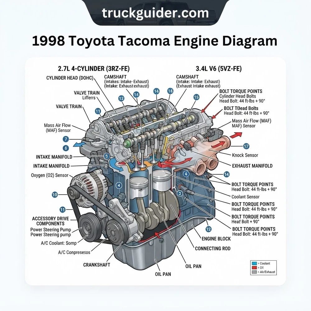
1998 Toyota Tacoma Engine Diagram: Mechanical Component Breakdown

Every engine option found within the 1998 Tacoma lineup—the 2.4L 2RZ-FE, the 2.7L 3RZ-FE, and the 3.4L 5VZ-FE—shares Toyota’s deep-skirt, cast-iron metallurgy coupled with lightweight aluminum alloy top ends. Reading a 1998 Toyota Tacoma engine diagram requires categorizing the engine bay into four distinct mechanical and electrical sub-assemblies: the core casting, the induction tract, air metering, and the secondary ignition circuit.
Cylinder Head, Valve Train, and Engine Block Assembly

The foundation of the engine consists of a heavy-duty, cast-iron engine block housing a micro-polished, forged steel crankshaft supported by five main bearing journals on the inline engines and four on the V6. Connecting rods forged from carbon steel link the crankshaft journals to lightweight aluminum alloy pistons fitted with two compression rings and an oil scraper ring assembly. The piston crowns feature valve relief pockets to maintain clearance under high engine speeds.
Mounted above the engine block via high-tensile torque-to-yield fasteners, the dual overhead camshaft (DOHC) aluminum cylinder head houses four valves per cylinder (two intake, two exhaust). The valve train utilizes a direct-acting shim-over-bucket or shimless tappet arrangement driven by induction-hardened camshaft lobes. On the 2RZ-FE and 3RZ-FE four-cylinder engines, the camshafts are driven by a dual-row timing chain assembly featuring an automatic hydraulic tensioner and oil jet lubrication. The 5VZ-FE V6 engine utilizes a high-strength, glass-fiber-reinforced timing belt driven directly from the crankshaft sprocket, synchronizing the exhaust camshafts, which in turn drive the intake camshafts through scissor-style backlash gears.
Connecting rod cap nuts: 25 ft-lbs (34 Nm) + 90° turn. Main bearing cap bolts: 45 ft-lbs (61 Nm) + 90° turn. Cylinder head bolts: 25 ft-lbs (34 Nm) + 90° + 90° double torque-turn sequence. Oil pan drain plug: 27 ft-lbs (37 Nm).
Throttle Body and Intake Plenum Architecture
The air intake tract transitions through a cast aluminum intake plenum and dual-stage or tuned runner lower intake manifold. The 1998 throttle body assembly incorporates a mechanical cable linkage to the accelerator pedal, a Rotary Solenoid Idle Air Control (IAC) valve positioned on the lower flange, and a linear 3-wire or 4-wire Throttle Position Sensor (TPS). Coolant bypass hoses route engine coolant through the base of the throttle housing to prevent throttle plate icing in freezing ambient conditions. Intake plenum gaskets must maintain an airtight seal against the lower runners to prevent unmetered air from entering the combustion chamber downstream of the throttle plate.
Mass Air Flow (MAF) Sensor and Air Induction Circuit
Metering incoming intake charge relies on a hot-wire Mass Air Flow (MAF) sensor bolted directly downstream of the engine air cleaner box. The 1998 Tacoma features a cylindrical cartridge-style housing containing a heated platinum filament and an ambient temperature thermistor (Intake Air Temperature or IAT sensor). As incoming intake air cools the heated wire, the onboard circuitry varies electrical current to maintain a steady temperature differential. This continuous voltage transition (typically ranging from 1.0V to 1.5V at warm idle up to 4.0V+ at wide-open throttle) sends an accurate mass-flow signal directly to the Engine Control Module (ECM).
Ignition System Configuration and Waste-Spark Pack Coils
For 1998, Toyota fully eliminated mechanical distributors across the entire Tacoma line. The four-cylinder engines (2RZ-FE and 3RZ-FE) utilize a coil-on-plug or dual waste-spark pack system, while the 5VZ-FE V6 operates a dedicated 3-coil waste-spark system mounted exclusively on the passenger-side (Bank 1: cylinders 1, 3, and 5) cylinder head. Each dual-tower coil fires its dedicated cylinder directly via a spark plug boot, while simultaneously discharging a secondary high-tension ignition wire routed across the top of the intake plenum to its companion cylinder on Bank 2 (cylinders 2, 4, and 6). Firing order for the 5VZ-FE is 1-2-3-4-5-6, with paired companion cylinders firing simultaneously (1-4, 2-5, 3-6) on compression and exhaust strokes.
1998 Toyota Tacoma Engine Diagram Configurations: 5VZ-FE, 3RZ-FE, and 2RZ-FE
The 1998 production year marked the mid-cycle enhancement of the first-generation Tacoma, including the introduction of the two-wheel-drive PreRunner platform, which used the elevated chassis, suspension components, and engine options of four-wheel-drive models. Understanding the subtle configuration changes between engine families prevents costly parts ordering errors and installation mismatches.
| Engine Code | Displacement & Configuration | Valve Train & Drive | Horsepower & Torque | Trim Applications |
|---|---|---|---|---|
| 2RZ-FE | 2.4L (2,438 cc) Inline-4 | DOHC 16-Valve / Dual Timing Chain | 142 hp @ 5,000 RPM 160 lb-ft @ 4,000 RPM | Base 2WD Regular & Xtracab |
| 3RZ-FE | 2.7L (2,693 cc) Inline-4 | DOHC 16-Valve / Dual Chain with Balance Shafts | 150 hp @ 4,800 RPM 177 lb-ft @ 4,000 RPM | 4WD Regular/Xtracab, 2WD PreRunner |
| 5VZ-FE | 3.4L (3,378 cc) 60° V6 | DOHC 24-Valve / Timing Belt + Scissor Gears | 190 hp @ 4,800 RPM 220 lb-ft @ 3,600 RPM | SR5 4WD, PreRunner V6, DLX V6 |
The 2.4-liter 2RZ-FE served primarily as the baseline powertrain for standard five-lug, rear-wheel-drive pickups. It utilizes a wet-sump oil pan configured with a rear pickup tube assembly and lacks the internal balance shafts found on the larger displacement four-cylinder.



The 2.7-liter 3RZ-FE shares the general overhead design of the 2RZ but incorporates twin counter-rotating balance shafts driven via gears off the crankshaft inside the lower engine block. This dampens secondary engine vibration characteristic of large four-cylinder displacements. In four-wheel-drive and PreRunner models, the 3RZ-FE uses a front-differential-clearing oil pan shape with a mid-to-rear sump configuration, making oil pan interchanges between standard 2WD and PreRunner trucks non-viable.
The 3.4-liter 5VZ-FE features significant modifications over the earlier 3.0-liter 3VZ-E truck engine it replaced. It incorporates a cast-iron engine block with enlarged water jackets, oil cooling passages for piston undersides, an oil cooler mounted between the engine block and oil filter bracket (standard on tow package configurations), and cross-flow cylinder heads engineered for optimal low-end torque delivery. Refer to our comprehensive Toyota Tacoma first-gen maintenance guide for service intervals specific to these engine options.
Accessory Belt Routing and Vacuum Diagrams for 1998 Tacoma Engines
Proper accessory component operation and engine emissions performance require precise routing of multi-rib serpentine drive belts and synthetic rubber vacuum harnesses. Incorrect tensioning leads to premature bearing failure on idler pullies, while misplaced vacuum lines disrupt closed-loop fuel control.
Never rely solely on aftermarket universal schematics for emissions plumbing. Toyota factory protocol specifies cross-referencing the underhood Vehicle Emission Control Information (VECI) label located on the underside of the steel hood directly above the radiator upper support. The label identifies engine displacement, calibration family, and the exact physical port-to-solenoid mapping.
Accessory Drive Belt Routing and Crankshaft Harmonic Balancer Alignment
The 1998 Tacoma utilizes an independent, multi-belt accessory drive arrangement rather than a single continuous serpentine belt. On the 5VZ-FE V6 engine, three separate V-ribbed belts originate from the crankshaft pulley (harmonic balancer):
- Alternator and Water Pump Belt: Routes from the innermost groove of the crankshaft harmonic balancer directly around the dual-groove water pump pulley and up to the high-mount alternator pulley. Belt tension is set via a manual mechanical adjusting jack screw located under the alternator casing (nominal deflection: 7.0–9.0 mm under a 22 lb load for a used belt; 5.0–6.5 mm for a new belt).
- Air Conditioning Compressor Belt: Routes from the center groove of the harmonic balancer down to the A/C compressor clutch pulley, running beneath an adjustable center idler pulley. Tension adjustments are executed through a top-accessible center bolt on the idler bracket assembly.
- Power Steering Pump Belt: Routes from the forward outer groove of the harmonic balancer directly to the power steering pump. Tension is adjusted by pivoting the pump body along an arched bracket slider using a pry bar pivot point against the casting (nominal deflection: 11.0–13.0 mm used; 8.0–10.0 mm new).
During belt installation or timing belt replacement, thoroughly inspect the crankshaft harmonic balancer. The balancer utilizes a vulcanized rubber elastomer bonding ring between the inner hub and outer serpentine pulley rim. Over time, heat cycles degrade this rubber bond, leading to harmonic balancer separation, outer ring slip, erratic belt wear, and severe timing pointer inaccuracies.
Vacuum Lines, EVAP Purge Routing, and VECI Label Identification
The emissions vacuum schematic on 1998 models features a combination of mechanical vacuum switching valves (VSVs) and an electronic Vapor Pressure Sensor controlling fuel vapor purge from the charcoal canister. On the upper intake plenum, multiple steel hard lines distribute manifold vacuum to the following critical sub-circuits:
- Fuel Pressure Regulator (FPR): Connected via a silicone vacuum hose to a regulated plenum port. Under high engine vacuum (idle), vacuum pulls the internal diaphragm against spring pressure, bypassing excess fuel back through the return line to maintain a steady differential pressure (approximately 38–44 psi with vacuum disconnected; 31–37 psi with vacuum applied).
- EVAP Purge VSV: Positioned adjacent to the intake plenum or driver-side inner fender apron. The ECM duty-cycles this solenoid to purge hydrocarbon vapors from the EVAP canister into the combustion chambers during warm cruise conditions.
- Exhaust Gas Recirculation (EGR) System: Models configured with federal and California emissions utilize an EGR Vacuum Modulator and an EGR VSV controlling line pressure to the mechanical EGR valve diaphragm on the rear intake crossover (non-existent on certain post-1998 clean air revisions).
Common Failure Points Across the 1998 Tacoma Cylinder Head and Block
While the first-generation Tacoma enjoys a reputation for exceptional powertrain longevity, specific physical wear items require systematic inspection when reading your engine schematic.



- Mass Air Flow (MAF) Sensor Contamination: The hot-wire element inside the MAF sensor housing attracts atomized crankcase oil vapor from the Positive Crankcase Ventilation (PCV) return port and airborne debris passing through aftermarket oiled filters. A contaminated wire causes under-reporting of intake air volume, generating diagnostic trouble codes (DTC) P0171 (System Too Lean Bank 1), intermittent hesitation, and transmission shift point flares under sudden acceleration.
- Vacuum Line Brittleness and EVAP VSV Failure: After more than two decades of heat exposure under the hood, factory synthetic rubber vacuum lines harden, split, and lose hoop tension over their cast intake barbs. Small cracks trigger evaporative emissions codes such as P0440, P0441, and P0446. The internal coil winding of the EVAP canister purge VSV frequently fails open-circuit when warm (proper cold resistance: 30–36 ohms at 68°F / 20°C).
- OBD-II Catalyst and O2 Sensor Degradation: The 1998 engine management system relies on dual heated oxygen sensors (upstream Bank 1 Sensor 1 for closed-loop air/fuel feedback; downstream Bank 1 Sensor 2 for three-way catalytic converter efficiency monitoring). Sensor internal heater circuits deteriorate, setting DTC P0135 or P0141. Ensure proper reference to testing oxygen sensor resistance values before component replacement.
- Cylinder Head Gasket and Valve Clearance Wear: On high-mileage 3RZ-FE and 5VZ-FE platforms, exhaust valve clearance naturally tightens over time as the valve face and valve seat contact surfaces erode into the cylinder head. If valve lash adjustments (utilizing replacement shims) are ignored, valves remain partially open under operating temperatures, leading to burned exhaust valves, catastrophic compression drop, and random misfire codes (P0300 through P0306). Head gasket failure can occur between the rear cylinder fire rings and water jackets on high-hour cooling systems.
- Oil Pan Half-Moon and Valve Cover Leaks: The stamped-steel oil pan seals against the iron engine block using Formed-in-Place Gasket (FIPG / RTV silicone). Front and rear differential chassis flex can stress this seal. On top, the semi-circular aluminum “half-moon” plugs installed in the cylinder head casting adjacent to the camshaft ends dry out, causing oil to leak downward onto the exhaust manifolds, bellhousing, and starter motor assembly.
The factory 3.4L 5VZ-FE engine is a non-interference design under standard valve timing conditions; a snapped timing belt will typically cause the engine to stall without piston-to-valve contact. However, excessive carbon accumulation on the piston crowns or aftermarket performance camshaft installations with increased lift can turn this engine into an interference setup, resulting in bent valves during timing loss.
How to Diagnose 1998 Toyota Tacoma Engine Diagram Faults with OBD-II Tools
Diagnosing driveability symptoms on a 1998 Tacoma requires bridging digital data from the on-board diagnostics port with mechanical checks on the physical components shown in your schematic.
- Interrogate the Diagnostic Link Connector (DLC3): Locate the 16-pin OBD-II diagnostic port inside the cabin beneath the lower dashboard knee bolster to the left of the steering column. Connect a compliant OBD-II diagnostic scan tool, power the ignition to the “ON” position (engine off), and pull active, pending, and permanent trouble codes. Note Freeze Frame parameters, paying specific attention to Engine Coolant Temperature (ECT), Calculated Engine Load, and Short/Long Term Fuel Trim (STFT/LTFT).
- Analyze Fuel Trim Deviations on the Intake Circuit: Start the engine and bring it to closed-loop operating temperature (ECT above 176°F / 80°C). Observe STFT and LTFT at idle. If LTFT is pinned high (+15% to +25%), an unmetered air leak exists. Inspect your engine schematic for components downstream of the MAF: check the accordion intake tube for tears, test the throttle body gasket, and introduce low-pressure smoke (1–2 psi) through the main intake tract to locate leaking vacuum lines, PCV hoses, or leaking intake plenum mating surfaces.
- Verify Ignition Coil and Secondary Lead Waveforms: For active misfires (P0300–P0306), trace the affected cylinder back to its ignition source on your schematic. For a 5VZ-FE, remember that an issue on Cylinder 4 can be caused by a defective coil pack mounted across the motor on Cylinder 1, or by a compromised secondary high-tension ignition lead. Measure secondary coil resistance using a digital multimeter: primary resistance across terminals 1 and 2 should read 0.67–1.05 ohms cold; secondary resistance across the high-voltage terminals should read 9.3–16.0 kΩ cold. Inspect the spark plug well for oil accumulation due to failed spark plug tube seals.
- Evaluate Throttle Body and Idle Control Operation: If rough idle or stalling is noted, cross-reference the Throttle Body and Intake Plenum schematic. Check the TPS output: signal voltage at idle should read approximately 0.6–0.9V on the signal wire (typically White/Red trace on 5VZ-FE) and sweep smoothly to approximately 3.5–4.7V at wide-open throttle without voltage drops. Clean the IAC valve rotor by removing the unit and washing out carbon build-up with intake-safe solvent; verify coil resistance across the IAC center ground terminal and side power pins reads approximately 17.0–24.5 ohms cold.
- Correlate Data Against the Toyota Factory Service Manual (FSM): Cross-examine sensor voltages at the ECM junction terminals located behind the glove box assembly. By back-probing specific pinouts (such as E1, E2, THW, and VG), confirm whether sensor voltage measured at the engine bay harness matches the actual value delivered to the ECM terminal board. This identifies harness degradation, rodent damage, or loose ground terminals (such as the main ground lugs bolted directly to the lower intake plenum and rear of the cylinder head). For deeper diagnostics, consult our guide to Toyota ECM pinout and wiring diagnostics.
1998 Toyota Tacoma Engine Diagram Reference Questions Answered
Where is the engine serial number located on a 1998 Toyota Tacoma?
On the 3.4L 5VZ-FE V6 engine, the engine serial number and block identifier are stamped onto a flat machined pad located on the forward driver-side (Bank 2) surface of the engine block, just beneath the cylinder head mating line and behind the power steering pump. On the 2.4L 2RZ-FE and 2.7L 3RZ-FE four-cylinder engines, the identification number is stamped on a machined vertical pad on the driver-side rear section of the engine block, near the transmission bellhousing flange.
Is the 1998 Toyota Tacoma 3.4L 5VZ-FE an interference or non-interference engine?
The OEM factory specification designates the 3.4L 5VZ-FE DOHC engine as a non-interference engine. If the timing belt snaps during operation, the valves will not contact the piston crowns under standard operating clearance. However, if the engine block or cylinder heads have undergone heavy surface decking, or if carbon build-up on the piston surface is severe, mechanical contact remains possible. The four-cylinder 2RZ-FE and 3RZ-FE engines utilize timing chains rather than rubber belts and are considered interference designs if chain failure occurs at dynamic engine speeds.
What is the correct spark plug firing order on a 1998 Tacoma 3.4L V6?
The firing order is 1-2-3-4-5-6. Cylinder identification is mapped with Bank 1 (passenger side) housing cylinders 1, 3, and 5 from front to back, while Bank 2 (driver side) houses cylinders 2, 4, and 6 from front to back. Because the 5VZ-FE uses a waste-spark ignition system with three coils mounted atop Bank 1, each coil concurrently fires two spark plugs: cylinder 1 fires with cylinder 4, cylinder 3 fires with cylinder 6, and cylinder 5 fires with cylinder 2.
Why does my 1998 Tacoma run lean (DTC P0171) after cleaning the throttle body?
Code P0171 indicates the engine management system has exhausted its fuel trim compensation threshold (+20% to +35%) due to an unmetered air leak or false sensor reading. During throttle body service, the rigid paper intake plenum gasket between the throttle housing and plenum can tear or fail to compress, allowing vacuum leaks. Additionally, technicians often displace old, brittle vacuum lines connected to the EVAP purge port or fuel pressure regulator, or wash carbon contamination directly onto the downstream MAF sensor hot wire if cleaning sprays were introduced through the intake plumbing while assembled.
What type of oil sealant should be used on the 1998 Tacoma oil pan?
Toyota specifies the use of ThreeBond 1282B, ThreeBond 1207B, or genuine Toyota Seal Packing 08826-00088 (commonly known as Toyota FIPG – Formed in Place Gasket) for both the upper and lower oil pan joints and half-moon plugs. Standard silicone RTV sealants should not be used, as engine oil and dynamic internal crankcase pressures will break down general-purpose sealants, causing oil leaks and potentially contaminating the oil pickup screen.
Step-by-Step Guide to Understanding the 1998 Toyota Tacoma Engine Diagram
Identify – Determine your engine designation (2.4L 2RZ-FE, 2.7L 3RZ-FE, or 3.4L 5VZ-FE) via the under-hood emissions label.
Locate – Find cylinder number one at the front of the block and trace timing reference marks on the crankshaft and camshaft sprockets.


Reference – Cross-examine the technical diagram to verify correct orientation of the cylinder head, valve train shims, and connecting rod caps.
Connect/Route – Align the timing belt or chain along tensioner pulleys and sprockets, verifying zero slack between crankshaft and camshaft drive gears.
Verify – Rotate the crankshaft by hand 720 degrees clockwise to verify mechanical timing marks re-align without valve-to-piston interference.
Troubleshoot – If mechanical timing is off or compression tests fail, re-check valve clearances and inspect camshaft lobe height against factory tolerances.