1999 Chevy Silverado AC System Diagram: 2026 Repair

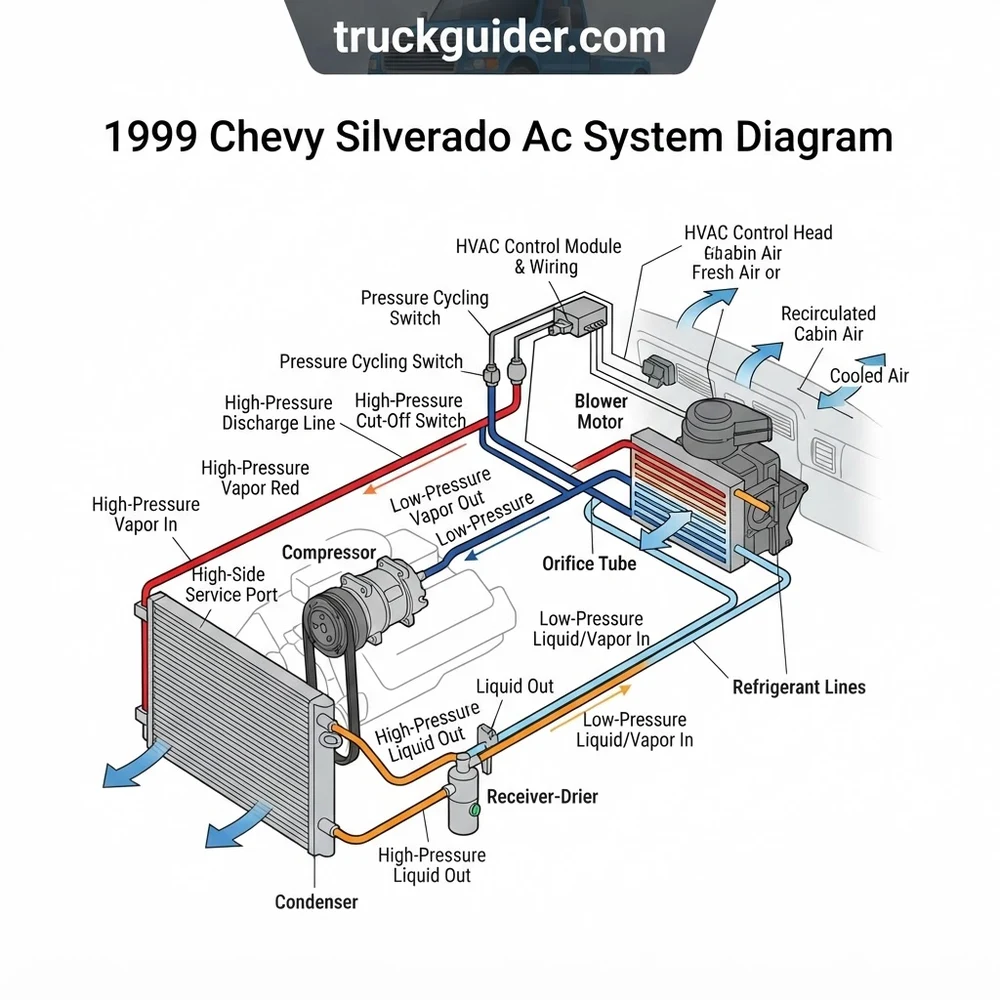
The 1999 Chevy Silverado AC system diagram maps an R-134a orifice-tube configuration. High-pressure refrigerant leaves the lower-passenger-side compressor, travels through the front condenser, passes the fixed orifice tube in the lower condenser line, enters the evaporator core, and returns via the accumulator to the compressor suction port at 30–45 psi.
📌 Key Takeaways
- Total refrigerant capacity is 1.81 lbs (29 oz) of R-134a paired with 8 oz of PAG 150 viscosity oil.
- The fixed orifice tube is located inside the lower condenser outlet line at the evaporator inlet junction.
- Low-pressure cycling switch mounts on the accumulator/drier, calibrated to open at 21 psi and close at 42 psi.
- Common failure points include compressor belly-seal leaks and burned blower motor resistor harnesses.
- Full refrigerant recovery and high-side evacuation require an EPA Section 609 certified recovery machine.
The heating, ventilation, and air conditioning (HVAC) platform on the first-generation GMT800 pickup relies on a precision-balanced thermodynamic cycle designed to handle severe cabin heat loads. Understanding the complete 1999 chevy silverado ac system diagram is essential for diagnosing intermittent cooling dropouts, compressor short-cycling, and electrical clutch circuit disengagements. Unlike modern variable-displacement systems, this truck utilizes a cycling clutch orifice tube (CCOT) arrangement paired with a dedicated accumulator-drier. Whether you are servicing a 4.3L V6 LU3, a 4.8L V8 LR4, or a 5.3L V8 LM7 Vortec engine, this technical guide provides factory-grade schematic breakdowns, circuit path traces, mechanical component locations, and step-by-step diagnostic procedures to ensure factory-spec vent discharge temperatures.



1999 Chevy Silverado AC System Diagram and Architectural Layout

The 1999 model year represents a pivotal engineering divergence for General Motors. While light-duty C/K models shifted to the modern GMT800 platform, certain heavy-duty variants and commercial cab-chassis models retained the outgoing GMT400 platform architecture. When referencing a 1999 chevy silverado ac system diagram, you must first verify your chassis type. The GMT800 platform introduced a completely redesigned engine bay layout, updated body control integration, and an improved air handler assembly compared to the 1998 Chevy C/K 1500 (GMT400) AC system.
The GMT800 layout relies on a CCOT (Clutch Cycling Orifice Tube) architecture charged with R-134a refrigerant. Unlike European and Asian automotive platforms that utilize Thermal Expansion Valve (TXV) systems with a liquid receiver-drier on the high-pressure liquid line, General Motors engineered this platform with a fixed restriction tube and a suction accumulator mounted on the low-pressure vapor line downstream of the evaporator. In a TXV system, a mechanical sensing bulb constantly modulates the refrigerant flow rate into the core based on evaporator outlet superheat, maintaining constant compressor engagement. Conversely, the CCOT design on the 1999 Silverado floods the evaporator core with a metering rate determined entirely by the fixed diameter of the orifice tube and the pressure differential across it.
Because the fixed orifice tube cannot adjust to fluctuating thermal cabin loads on its own, system regulation is governed by cycling the compressor clutch on and off via a low-pressure switch mounted directly to the accumulator shell. Ensure your diagnostic routine accounts for this cycling behavior; continuous compressor operation in ambient temperatures below 85°F (29°C) indicates an overcharged condition or a stuck pressure switch.
The physical plumbing routes the high-pressure gas from the compressor discharge port across the front-mounted condenser heat exchanger, pushes condensed liquid through the liquid line where the fixed orifice tube meters it, and allows it to boil inside the evaporator core housed within the passenger-side cabin air handler. Low-pressure vapor and residual liquid oil then exit through the suction line into the accumulator before entering the compressor suction manifold. Proper reference to the system layout prevents costly misdiagnoses, such as replacing a functioning compressor when an upstream restriction or cycling switch drift is the true point of failure.
1999 Silverado AC System Diagram: Core Components Labeled
Every mechanical and thermodynamic element shown on the 1999 chevy silverado ac system diagram serves a dedicated role in the continuous phase-change cycle. Below is a comprehensive breakdown of each primary component, its exact physical location in the engine bay or cabin bulkhead, and its operational baseline according to OEM engineering specifications.
| Component | Physical Location | OEM Specification / Function | Interface Connection |
|---|---|---|---|
| AC Compressor | Lower passenger side of engine block (Vortec V8); belt-driven via dedicated lower accessory drive belt. | Delphi HT6 or Denso 10S17F/10S20F; pumping displacement: ~160-200cc; pressurized gas discharge. | Sealed manifold block secured with single M10 bolt (torque to 15 lb-ft / 20 Nm). |
| AC Condenser | Front core support directly ahead of engine coolant radiator; primary external heat exchanger. | Aluminum parallel-flow design; rejects latent heat of condensation to external ambient airflow. | Block fittings: top right (discharge inlet), bottom right (liquid line outlet). |
| Fixed Orifice Tube | Inside the metal liquid line junction near the passenger firewall, between condenser outlet and evaporator inlet. | White plastic body with internal metal tube; 0.072-inch calibrated restriction orifice with integrated fine-mesh filter screens. | Threaded compression coupling fitting with internal HNBR O-ring (torque to 12 lb-ft / 16 Nm). |
| Evaporator Core | Inside the HVAC air handler module beneath the passenger-side dashboard bulkhead. | Aluminum plate-and-fin heat exchanger; absorbs cabin heat as low-pressure liquid refrigerant boils into vapor. | Spring-lock or threaded push-connect liquid inlet; flange coupling to accumulator inlet. |
| Accumulator-Drier | Mounted on passenger firewall bulkhead directly adjacent to the evaporator core outlet. | Internal desiccant bag (XH-7 or XH-9) absorbs moisture; vapor separator prevents liquid refrigerant slugging into compressor. | Direct flange connection to evaporator outlet pipe; female 1/4-inch Schrader port for cycling switch. |
| Blower Motor | Mounted to the bottom of the HVAC air handler plenum beneath the passenger lower dash panel. | 12V DC permanent magnet motor; pulls air through return duct / cowl and forces it across evaporator and heater core. | Two-pin harness connector (Purple = 12V supply; Black = Ground/resistor control return). |
Factory R-134a refrigerant charge capacity for a standard single-cab or extended-cab 1999 Silverado 1500 (Front A/C only, C60 manual climate control) is exactly 1.81 lbs (29.0 oz / 0.82 kg). Total system lubrication oil capacity is 8.0 fl oz (237 ml) of PAG 150 (Delphi compressors) or PAG 46 (Denso units). Always confirm the label on your front upper radiator shroud before charging.
When servicing this system, consult our companion technical documentation regarding Vortec serpentine belt routing guide setups to verify that the separate lower compressor stretch belt or dedicated tensioner assembly is properly loaded without exceeding bearing load limits on the compressor clutch snout.


Tracing Refrigerant Flow Through the Air Handler and Lines
To pinpoint localized temperature drops, thermal blockages, and non-condensable gas contamination on the 1999 chevy silverado ac system diagram, you must follow the thermodynamic path of the R-134a refrigerant in sequence from the mechanical pump back through the cab distribution housing.
- Low-Pressure Vapor Intake and Superheating: The cycle initiates at the suction manifold port on the rear/side head of the AC compressor. The compressor pulls superheated low-pressure vapor out of the top of the accumulator canister at approximately 20 to 35 psi (138 to 241 kPa) and 35°F to 45°F (2°C to 7°C).
- High-Pressure Mechanical Compression: The internal pistons compress the vapor into a dense, high-temperature, high-pressure gas. It exits through the discharge manifold at pressures ranging between 150 and 250 psi (1034 to 1724 kPa) and temperatures exceeding 160°F to 195°F (71°C to 91°C). Directly at or near this discharge line sits the high-side service port (16mm quick disconnect).
- Condensation Across the External Heat Exchanger: The superheated gas passes into the top inlet of the aluminum AC condenser. As forced ambient airflow crosses the cooling fins—drawn by the mechanical viscous fan clutch—latent heat transfers out of the refrigerant into the environment. By the time the refrigerant reaches the lower discharge rows of the condenser, it has condensed entirely into a subcooled, high-pressure liquid state at roughly 110°F to 130°F (43°C to 54°C).
- Liquid Line Passage and Fixed Metering: The subcooled liquid flows through the rigid aluminum liquid line toward the cab bulkhead. Inside the line junction immediately upstream of the evaporator inlet, the refrigerant hits the fixed orifice tube. The 0.072-inch restriction forces a sudden pressure drop from ~200 psi down to roughly 25 to 30 psi. This drop causes the liquid to atomize into a cold, low-pressure liquid-vapor fog.
- Heat Absorption in the Cab Air Handler: The atomized refrigerant enters the evaporator core inside the HVAC air handler module. As the blower motor forces warm air pulled from the cabin return duct across the core’s fins, the low-pressure liquid boils, absorbing tremendous latent heat from the air. The chilled air continues past the HVAC temperature blend door actuator and into the distribution ductwork, exiting the cabin vents between 38°F and 44°F (3.3°C and 6.7°C).
- Accumulation and Vapor Separation: What exits the evaporator core is a saturated mix of cold vapor, unevaporated liquid droplets, and circulating PAG oil. This mixture enters the side inlet of the accumulator-drier. Liquid settles at the bottom of the canister where a desiccant bag traps trace ambient moisture, while an internal J-tube draws dry vapor from the top space. A calibrated 0.040-inch oil bleed hole at the bottom of the J-tube allows a measured stream of PAG oil to return to the compressor sump. The low-side service port (13mm quick disconnect) is located directly on this accumulator line.
Never attempt to charge liquid refrigerant directly into the low-side service port on the accumulator while the engine is running at high RPM. Charging liquid directly into the low-pressure line can overwhelm the accumulator J-tube and cause liquid slugging, which catastrophically bends internal compressor reeds and shatters piston plates.
1999 Chevy Silverado AC Wiring Diagram and Switch Operation
The electrical control loop on the 1999 chevy silverado ac system diagram combines mechanical driver inputs with solid-state logic managed by the Powertrain Control Module (PCM). The compressor clutch does not receive battery voltage directly from the dash controls. Instead, the A/C control head makes a request that must pass multiple pressure thresholds and engine parameter checks before the PCM energizes the compressor clutch coil.
| Circuit Element | Wire Color / Connector Pin | Normal Operating Voltage | Operational Switching Logic |
|---|---|---|---|
| A/C Request Signal | Dark Green / White (Dash Head to PCM Pin C2-17) | 12V DC when A/C switch depressed | Sends operator request to PCM; drops to 0V when climate dial set to OFF or blower speed 0. |
| Low-Pressure Cycling Switch | Light Blue & Dark Green (Series loop on Accumulator) | 12V DC across contacts | Normally Closed. Opens contacts when suction pressure drops below 21-24 psi (145-165 kPa); re-closes at 40-44 psi (276-303 kPa). |
| High-Pressure Cutoff Switch | Dark Green / White (Series loop near Compressor discharge) | 12V DC (Pass-through signal) | Normally Closed. Opens contacts if head pressure exceeds 420-450 psi (2896-3103 kPa); resets closed below 250-300 psi. |
| AC Compressor Clutch Relay | Underhood Fuse Block (Relay Pin 85, 86, 87, 30) | Pin 30/86: 12V constant/switched; Pin 85: Ground control | PCM Pin C2-43 commands ground to relay coil pin 85 when all engine safeties and pressure switch conditions are verified. |
| Clutch Coil Feed | Dark Green (Relay Pin 87 to Compressor Clutch connector) | 12V DC when relay active; 0V when disengaged | Drives electromagnetic clutch coil against pulley face. Coil resistance spec: 3.2 to 4.4 Ohms at 68°F. Ground wire is Black to engine block. |
The PCM clutch inhibit logic protects both the engine and the air conditioning mechanicals. According to factory powertrain programming, the PCM immediately opens the ground driver circuit to the AC compressor clutch relay under any of the following operational conditions:
- Wide Open Throttle (WOT) acceleration where throttle position sensor (TPS) input exceeds 95% at low-to-mid RPM.
- Engine cranking state or engine speed dropping below 500 RPM.
- Excessive engine RPM exceeding redline limits (>5,200 RPM).
- Engine coolant temperature (ECT) sensor reporting overheating conditions exceeding 240°F (116°C).
For cross-referencing dash harness pinouts and underhood fuse distribution blocks, refer to our comprehensive guide on GMT800 electrical schematics to trace wiring harnesses between the bulkhead firewall and dash cluster.
Troubleshooting Compressor, Pressure, and Airflow Failures
When the air conditioning system on your 1999 Silverado malfunctions, diagnosing the underlying issue requires systematic analysis using an R-134a manifold gauge set, a digital multimeter, and temperature probes. Use this targeted troubleshooting guide to trace common component failures:


- Rapid Clutch Cycling (Short Cycling every 2-5 seconds):
Symptom: The compressor engages for 2 to 4 seconds, clicks off, pauses for 3 seconds, and repeats. The dash vents discharge slightly cool or warm air.
Cause: Undercharged refrigerant condition. As the compressor pulls vapor from the low side, insufficient refrigerant mass causes suction pressure to plunge instantly below the low-pressure cycling switch cutoff threshold (21 psi). Once the compressor disengages, pressure rapidly equalizes back up to 45 psi, re-closing the switch.
Diagnostic Step: Connect manifold gauges. If resting static pressure on an 80°F day is below 60 psi, check for physical oil leakage staining the lower compressor case, evaporator drain, or condenser corners, and recharge using an electronic leak detector. - Compressor Will Not Engage (Zero Clutch Pull-In):
Symptom: Pressing the A/C button produces an illuminated indicator light, but the compressor clutch hub remains stationary while the outer belt pulley spins freely.
Cause: Blown A/C fuse (10A A/C COMP in underhood box), open high-pressure cutoff switch, failed clutch coil, or missing PCM ground command.
Diagnostic Step: Remove the A/C relay. Measure across terminal 30 and terminal 87 using an automotive fused jumper wire (15A rated). If the clutch clicks and engages, the high-current coil and wiring are intact. Next, probe terminal 85 with a test light connected to 12V while commanding A/C ON in the cabin. If the test light fails to illuminate, probe the low-pressure cycling switch on the accumulator. Jumper the two terminals of the switch harness with a fused lead; if the compressor runs, replace the defective pressure cycling switch. - High Head Pressure with Warm Dash Air (High Side >350 psi, Low Side >55 psi):
Symptom: High side spikes dangerously toward the cutoff limit of 420 psi while the low side remains elevated. The engine may labor or run hot at idle.
Cause: Lack of condenser heat exchange or overcharging. This commonly stems from a failed mechanical radiator fan clutch slipping at idle speeds, dense mud/debris packing the fins between the radiator and AC condenser, or excess refrigerant oil.
Diagnostic Step: Inspect the air gap between the front condenser and radiator for packed leaves and debris. Check the mechanical fan clutch: with the engine hot and turned off, spin the fan blades by hand; if the fan spins freely more than 1/2 turn without stiff viscous resistance, replace the viscous fan drive unit immediately. - Normal Gauge Pressures but Cabin Discharges Full Heat:
Symptom: Manifold gauges show ideal pressures (Low side: 30 psi; High side: 175 psi at 80°F ambient), the accumulator sweat line is ice cold with heavy condensation, yet the cabin center vents discharge 120°F (49°C) air.
Cause: Mechanical failure of the HVAC temperature blend door actuator or a stripped blend door axle. The blend door is stuck fully open to the heater core plenum, blending max engine coolant heat over the frozen evaporator air.
Diagnostic Step: Locate the blend door actuator directly under the bottom center of the dash assembly. Connect an OBD-II scan tool capable of reading GM body modules to verify HVAC control head target vs. actual counts. If the plastic gears inside the actuator have fractured, perform our step-by-step procedure detailed in the Chevy blend door actuator replacement tutorial. - Blower Motor Inoperative on Speeds 1, 2, or 3 (Runs Only on Speed 4/5):
Symptom: Airflow from the dash vents is completely absent on lower fan settings but operates at maximum velocity when the selector knob is rotated to the highest setting.
Cause: Thermal fuse failure or burned resistor traces on the blower motor resistor pack, situated adjacent to the blower motor housing in the passenger footwell. Speed 5 bypasses the resistor entirely and routes battery voltage directly through the high-speed relay.
Diagnostic Step: Disconnect the multi-pin connector at the blower resistor. Inspect the terminals for plastic melting or heat deformation (a common GMT800 issue). Check continuity across the resistor coils using an ohmmeter. Always replace the blower motor alongside the resistor if the motor shows an amperage draw exceeding 14 Amps, as an aging, high-resistance blower motor motor will promptly burn out the replacement resistor block.
1999 Chevy Silverado AC System Diagram FAQs and Diagnostic Solutions
What is the exact R-134a refrigerant and PAG oil capacity for a 1999 Silverado?
For standard single-system (front A/C only) 1999 Chevy Silverado 1500, 2500, and 3500 pickups, the OEM factory refrigerant capacity is 1.81 lbs (29.0 oz / 0.82 kg) of pure R-134a. The factory total oil fill is 8.0 fluid ounces (237 ml). Use PAG 150 viscosity oil for factory Delphi HT6 compressors, or PAG 46 viscosity oil if an updated Denso 10S-series replacement compressor has been retrofitted. Never substitute ester oil or universal blends, as they deteriorate the HNBR green O-rings over extended operational cycles.
Where is the fixed orifice tube located on a 1999 Silverado?
The fixed orifice tube is housed internally inside the high-pressure liquid line fitting on the passenger-side firewall area, located just downstream of the condenser outlet and roughly 6 to 8 inches ahead of the evaporator core inlet connection. To service it, recover the refrigerant, disconnect the threaded line coupling using two counter-holding open-end line wrenches (19mm and 22mm), and extract the plastic-bodied tube using needle-nose pliers or an orifice tube removal tool. Lubricate the replacement tube’s O-rings with fresh PAG oil and ensure the shorter screen end points directly toward the evaporator core.
How do you safely bypass the low-pressure switch to test the compressor clutch?
Locate the low-pressure cycling switch threaded onto the passenger-side accumulator canister Schrader valve. Unclip the two-wire harness connector (featuring light blue and dark green wires). Insert an insulated, fused automotive jumper wire (10-15A) directly between the two harness terminals with the ignition key turned ON and the dash A/C button activated. If the compressor clutch clicks and locks into place, the electrical harness, relay, fuse, and PCM driver circuit are functioning properly, confirming that the switch has either tripped due to low system pressure or has experienced internal contact failure.
What causes the AC to blow cold at highway speeds but warm while idling in traffic?
This condition points to insufficient airflow velocity through the external condenser heat exchanger or reduced compressor volumetric efficiency at low RPM. The primary culprit on the 1999 Silverado is a worn mechanical fan clutch that fails to lock up when exposed to ambient underhood heat, preventing adequate air draw through the condenser at idle. Secondary causes include severe fin debris buildup between the condenser and the radiator core, or worn internal compressor piston rings that cannot build adequate discharge pressure until the engine achieves road speeds above 1,800 RPM.
Why is the accumulator sweating or freezing over on the outside?
Light sweating and cold condensation on the exterior metal shell of the accumulator is completely normal and indicates that the fixed orifice tube is correctly flooding the evaporator core with liquid refrigerant, with excess liquid falling safely into the accumulator canister. However, if the accumulator, suction line, and evaporator housing develop thick frost or solid white ice, this indicates severe low airflow across the evaporator (caused by a heavily clogged cabin filter retrofit, an inoperative blower motor, or an internally collapsed return duct) or an undercharge condition that has forced the low-side boiling point below 32°F (0°C) without tripping the cycling switch.
Step-by-Step Guide to Understanding the 1999 Chevy Silverado Ac System Diagram
Identify – Locate the high-side service port near the condenser and low-side port on the accumulator.
Locate – Map the compressor clutch power feed (Dark Green wire) from the underhood AC relay block.



Reference – Trace the schematic from the HVAC control head to the blower motor resistor pack beneath the glovebox.
Connect/Route – Connect manifold gauges ensuring the red line secures to the liquid line and blue to the accumulator.
Verify – Start the engine, command max AC, and verify compressor engagement with a 12V probe at the clutch coil.
Troubleshoot – Check the 10A AC mini-fuse and 40A HVAC blower fuse if the compressor clutch or fan fails to engage.