The Definitive Technical Guide to the 2006 Dodge Ram 1500/2500/3500 Electrical System: Fuse Box Locations, TIPM Diagnostics, and Repair Strategies
The 2006 Electrical Paradigm Shift
The 2006 model year represents a watershed moment in the engineering history of the Dodge Ram. While the sheet metal and powertrain options—including the legendary 5.9L Cummins turbo diesel and the potent 5.7L Hemi V8—carried over with familiar robustness, the underlying electrical architecture underwent a radical transformation.
This was the year DaimlerChrysler (as the entity was then known) moved away from the traditional, decentralized fusing systems of the early 2000s and fully embraced the Controller Area Network (CAN) bus integration via a centralized node: the Totally Integrated Power Module (TIPM).
For owners, mechanics, and technicians accustomed to the 2002–2005 third-generation Rams, the 2006 layout can be a source of significant confusion and frustration. The most common query—”Where is the interior fuse box?”—stems from decades of automotive design convention where a secondary junction block was always located inside the cabin, usually near the driver’s knee or the dashboard end-cap, to service low-amperage accessories like the radio, cigarette lighter, and interior lighting. In the 2006 Dodge Ram, this component was eliminated entirely.
This report serves as an exhaustive technical reference for the 2006 Dodge Ram 1500, 2500, and 3500 electrical systems. It moves beyond simple diagrams to explore the engineering logic behind the TIPM, the specific physical locations of critical circuit protection devices, the metallurgy and thermal characteristics of the fuses employed,
and the diagnostic protocols necessary to address the module’s notorious failure points, particularly the fuel pump relay. By synthesizing data from technical service bulletins, pinout charts, and aftermarket engineering analyses, we provide a definitive roadmap for maintaining the electrical integrity of these heavy-duty trucks.
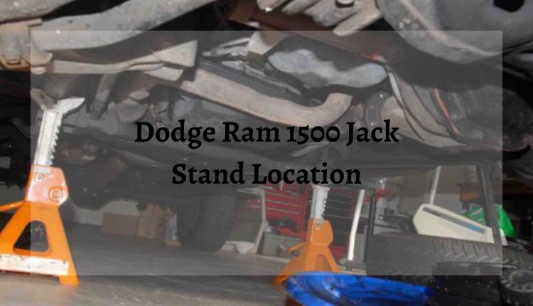
2006 Dodge Ram
Fuse Box Locations
Electrical gremlins? 90% of the time, it’s a simple fuse. This data-driven guide breaks down the Integrated Power Module (IPM) layout, interior locations, and high-frequency failure points to get your rig back on the road.
Locating the Power Centers
The 2006 Ram utilizes a distributed power system. Unlike older trucks, logic and power are separated into two distinct zones. Accessing the wrong box is a common rookie mistake.
Integrated Power Module (IPM)
Under Hood • Driver’s Side • Near Battery
Interior Fuse Panel
Lower Dash • Driver’s Side • Near Brake Pedal
The “Usual Suspects”
Based on analysis of owner forums and repair tickets, these are the most frequently blown fuses in the 2006 Dodge Ram. Check these first if you experience issues.
Failure Frequency Index
*Index value represents relative frequency of search volume and forum reports. Cigarette lighters often fail due to charging device overload.
1. Cigar Lighter / Power Outlet
Typically Fuse #38 (20A) or Fuse #42. Often blows when using high-draw inverters or faulty phone chargers.
2. Trailer Tow Park Lamps
The towing harness is exposed to the elements. Short circuits here are common, knocking out Fuse #34 or #35.
3. Radio / Audio System
Unexpected silence? Fuse #28 or #51 are the primary power feeds for the head unit and amplifier.
System Load Distribution
Understanding the amperage ratings helps identify the circuit type. High amp fuses (30A+) usually control motors (Starter, ABS, Fan), while low amp fuses protect sensitive electronics.
Visual Identification Matrix
Automotive fuses are color-coded by industry standard. Never replace a fuse with a higher rating than specified (e.g., don’t put a 30A Green in a 10A Red slot), or you risk an electrical fire.
How to Diagnose a Blown Fuse
Locate the Diagram
Check the underside of the fuse box cover. It contains a grid map corresponding to the fuses underneath.
Visual Inspection
Pull the suspect fuse using the white plastic puller tool inside the IPM. Look at the “U” shaped wire inside the translucent plastic.
Wire is Broken / Black?
The fuse has done its job.
Wire is Intact?
The fuse is good.
The Myth of the Interior Fuse Panel
The persistent search for an interior fuse box in the 2006 Ram is a phantom chase. In the previous electrical architecture (2002–2005), the vehicle utilized a Power Distribution Center (PDC) under the hood for high-current loads and a Junction Block (JB) inside the cab for logic and accessory power. The 2006 redesign consolidated these functions. The interior Junction Block was deleted, and its circuits were migrated to the engine bay, integrated into the TIPM.
This consolidation was driven by the desire to reduce wiring harness weight (copper mass), simplify assembly line complexity, and leverage the growing capabilities of digital control modules. However, it means that if a driver experiences a failure of an interior component—such as the instrument cluster, the radio, or the 12V power outlet—they must exit the vehicle and lift the hood to find the relevant fuse. There is no access panel on the dashboard side, nor is there a fuse block beneath the steering column.
1.2 Scope of Analysis
This document covers the following core areas:
- Physical Architecture: Location and access to the TIPM.
- Component Analysis: Detailed breakdown of the 42+ fuse circuits, including wire colors, load ratings, and connected systems.
- The TIPM Controversy: An in-depth look at the integrated relay failures, specifically the fuel pump relay, and the engineering flaws that lead to “crank-no-start” conditions.
- Diagnostic Procedures: Step-by-step methodologies for resetting the logic board, testing for parasitic draw, and verifying circuit continuity.
- Aftermarket Solutions: Evaluation of bypass cables, solid-state repairs, and replacement modules.
The Totally Integrated Power Module (TIPM): Architecture and Logic
To understand the fuse box of the 2006 Ram, one must first understand the device that houses it. The TIPM is not merely a plastic box containing fusible links; it is a sophisticated computer that manages the distribution of power throughout the vehicle. It acts as a gateway for the vehicle’s CAN bus network, translating signals between the Engine Control Module (ECM), the Instrument Cluster (CCN – Cabin Compartment Node), and other peripheral modules.
Physical Location and Environmental Factors
The TIPM is located in the engine compartment on the driver’s side (left side), positioned between the battery and the inner fender well.
- Orientation: The module is mounted horizontally.
- Protection: It is covered by a removable black plastic lid secured by retention tabs.
- Environment: Being located in the engine bay exposes the TIPM to significant thermal cycling. It endures the ambient heat of the engine block (especially in the confined space of the V8 and diesel variants) and the rapid cooling of environmental air. This thermal stress is a contributing factor to the fatigue of internal solder joints and the degradation of relay contacts over time.
The “Gateway” Function
The TIPM serves as the central nervous system for the truck. Unlike a traditional fuse box that simply passes current when a switch is closed, the TIPM makes logic-based decisions.
- Example: When you turn on the headlights, the switch on the dash sends a low-voltage data signal to the Instrument Cluster (CCN). The CCN sends a digital message over the CAN bus to the TIPM. The TIPM’s microprocessor receives this request, verifies that the conditions are met, and then energizes the internal drivers to send 12V power to the headlamp bulbs.
- Implication: This means that a failure of the headlights is not always a fuse or a bulb; it can be a logic error, a corruption of the data bus, or a failure of the specific driver chip inside the TIPM. This architecture allows for advanced features like “follow-me-home” lighting and daytime running lamps but complicates diagnostics significantly.
Circuit Board Construction
The 2006 TIPM utilizes a multi-layer Printed Circuit Board (PCB). Critical relays—such as those for the fuel pump, windshield wipers, and door locks—are often soldered directly to this board rather than being socketed. This “integrated” design is the root cause of the high replacement costs associated with the unit. When a $5 mechanical relay fails inside the module, the official repair procedure from the manufacturer is to replace the entire $900+ module rather than servicing the individual component
Comprehensive Fuse Matrix and Circuit Analysis
The 2006 Dodge Ram TIPM utilizes a combination of Mini Fuses (ATM) for control circuits and lower amperage loads, and J-Case Cartridge Fuses for high-current applications. The J-Case fuses are distinctively box-shaped and are designed to handle high inrush currents with minimal voltage drop, making them ideal for the heavy-duty demands of a pickup truck.
The following analysis details every fuse position found in the 2006 TIPM. This data aggregates information from technical service manuals, owner observations, and wiring diagrams to provide the most accurate possible legend.
Detailed Fuse Legend
| Fuse | Amp Rating | Color | Type | Primary Circuit & Detailed Function |
| 1 | 20A | Yellow | Mini | Power Outlet – Console (Battery Feed). This circuit is typically “hot at all times,” allowing for device charging when the vehicle is off. It feeds the center console outlet. |
| 2 | 20A | Yellow | Mini | Cluster / CCN / BTSI. Powers the Instrument Cluster (Cabin Compartment Node) and the Brake Transmission Shift Interlock. If this fuse blows, the shifter may get stuck in Park. |
| 3 | — | — | — | Spare / Not Used |
| 4 | 20A | Yellow | Mini | Transmission Control Module (TCM). Primarily for late-build 2006 models or 2007 crossovers. Early 2006 models may use this slot for other logic. |
| 5 | 20A | Yellow | Mini | Power Sunroof. Feeds the overhead sunroof control module. |
| 6 | 40A | Green | J-Case | Occupant Classification Module (OCM) / Diesel Fan. Critical safety circuit for the passenger airbag weight sensor. On Diesel models, it powers the Wastegate Solenoid and Viscous Fan Drive. |
| 7 | 15A | Blue | Mini | Reverse Lockout Solenoid. Specific to the SRT-10 (Viper engine) manual transmission to prevent accidental shifting into reverse at speed. |
| 8 | 10A | Red | Mini | Heated Mirrors. Powers the resistive heating elements in the side mirrors for defrosting. |
| 9 | 30A | Pink | J-Case | Final Drive Control Module (Power Wagon). Provides power to the locking differential and sway bar disconnect motors on Power Wagon trims. |
| 10 | 5A | Tan | Mini | PCM / ECM Logic / Trans Range Sensor. A critical “Keep Alive” and logic power source for the Powertrain Control Module (gas) or Engine Control Module (diesel). Also feeds the Clutch Interlock on manuals. |
| 11 | 20A | Yellow | Mini | Radio / Data Link / Hands-Free. Powers the head unit, the OBDII diagnostic port (Data Link Connector), and the UConnect hands-free module. A blown fuse here prevents scan tools from reading codes. |
| 12 | 30A | Pink | J-Case | Trailer Tow Brake Provision. Supplies the high-current 12V feed to the aftermarket trailer brake controller harness under the dash. Essential for towing heavy loads. |
| 13 | 25A | Clear | Mini | Anti-Lock Brakes (ABS) Module. Logic power for the ABS computer (Anti-Lock Brake Module). |
| 14 | 15A | Blue | Mini | Left Front Park/Turn Lamp. Powers the parking light and turn signal filament for the front left housing. Controlled by TIPM logic. |
| 15 | 20A | Yellow | Mini | Trailer Tow Park Lamps. Independent circuit for trailer running lights. If trailer lights fail but truck lights work, check this fuse. |
| 16 | 15A | Blue | Mini | Right Front Park/Turn Lamp. Powers the parking light and turn signal filament for the front right housing. |
| 17 | — | — | — | Spare / Not Used |
| 18 | 40A | Green | J-Case | Anti-Lock Brakes (ABS) Pump. High-amperage feed for the hydraulic pump motor in the ABS unit. |
| 19 | 30A | Pink | J-Case | Trailer Tow Battery Charge. Provides the 12V “Hot” line to the 7-way trailer connector (Pin 4) to charge the trailer’s breakaway battery. |
| 20 | 10A | Red | Mini | Occupant Restraint Controller (ORC). Powers the airbag control module. |
| 21 | 10A | Red | Mini | Passenger Airbag Off Switch. Powers the indicator light and switch for disabling the passenger airbag. |
| 22 | 20A | Yellow | Mini | Ignition Switch. Main feed to the ignition cylinder logic. |
| 23 | 10A | Red | Mini | HVAC / Interior Lighting. Powers the AC control head and overhead console lighting. |
| 24 | 20A | Yellow | Mini | Transmission Control Relay / Subwoofer. Logic power for the transmission relay (gas/diesel) or the factory subwoofer amp (SRT). |
| 25 | 10A | Red | Mini | Power Mirrors / Door Node. Powers the adjustment motors for the side mirrors and the driver door switch node. |
| 26 | 15A | Blue | Mini | Brake Switch / CHMSL. Powers the Center High Mount Stop Lamp and the brake pedal position switch signal. |
| 27 | 40A | Green | J-Case | Power Seats. High-current feed for the driver and passenger power seat motors. |
| 28 | 10A | Red | Mini | PCM / ECM Run/Start. Critical ignition-switched signal to the engine computer. Also powers the ABS logic and Steering Angle Sensor. |
| 29 | 10A | Red | Mini | Door Locks (Passenger) / Transfer Case. Powers the passenger door lock switch and the 4WD selector switch. |
| 30 | 15A | Blue | Mini | Spare (Sometimes listed for AC Clutch in other years, but usually relay-controlled in 2006). |
| 31 | 15A | Blue | Mini | Engine Control (Gas) / Shift Motor. Power for the 4WD transfer case shift motor (Electronic Shift-on-the-Fly). |
| 32 | 10A | Red | Mini | HVAC / Heated Seats / Adjustable Pedals. Logic power for comfort accessories. |
| 33 | 10A | Red | Mini | Spare |
| 34 | — | — | — | Spare |
| 35 | 15A | Blue | Mini | Cluster Illumination. Powers the background lighting of the gauge cluster. |
| 36 | 25A | Clear | Mini | Premium Audio Amplifier. Power for the factory Infinity or Alpine sound system amplifier. |
| 37 | 15A | Blue | Mini | Diesel VGT / Turbo Shutdown. Specific to 6.7L (late 2006/2007) or 5.9L systems requiring turbo logic. |
| 38 | 20A | Yellow | Mini | Power Outlet – Instrument Panel (Ignition Switched). This outlet only works when the key is on. Commonly used for radar detectors. |
| 39 | 10A | Red | Mini | Seat Belt Tensioner / Subwoofer. Safety system power or audio depending on trim. |
| 40 | 20A | Yellow | Mini | Cigarette Lighter. Powers the primary lighter socket. |
| 41 | — | — | — | Spare |
| 42 | 30A | Pink | J-Case | Diesel ECM / Intake Heater. High-current feed for the Diesel Engine Control Module. |
Deep Dive: The Power Outlet Configuration
A frequent point of confusion for owners is the behavior of the multiple power outlets. The 2006 Ram features a split-logic design for its 12V auxiliary power, protected by three separate fuses.
- Fuse #1 (20A): This circuit is connected directly to the battery bus. It remains live regardless of the ignition key position. This is designed for the center console outlet, allowing owners to charge cellular telephones or run portable refrigerators while the truck is parked.
- Fuse #38 (20A): This circuit is ignition-switched. It only energizes when the key is in the ACC or RUN position. It feeds the outlet on the instrument panel, ensuring that high-draw accessories like GPS units or dash cams do not drain the battery overnight.
- Fuse #40 (20A): This circuit specifically feeds the cigarette lighter element. It is typically ignition-switched to prevent accidental overheating if the lighter element is depressed and the vehicle is left unattended.
The Trailer Towing Circuits
The 2006 Ram was engineered as a tow vehicle, and the TIPM reflects this with dedicated isolation circuits. Unlike passenger cars where trailer lights are often spliced into the vehicle’s tail lights, the Ram uses independent fusing.
- Isolation: Fuse #15 and #19 ensure that a short circuit in a trailer’s wiring—common due to submersion in water or corrosion—does not blow the fuse for the truck’s own tail lights. This safety feature ensures the truck remains visible even if the trailer wiring fails.
- Brake Provision (Fuse #12): This 30A J-Case fuse is critical for safety. It provides the heavy current needed to actuate the electromagnets in a trailer’s drum brakes. If this fuse is blown or missing, the trailer brakes will not function, placing the entire braking load on the truck’s hydraulic system.
Technical Analysis of Fuse Types: Mini vs. J-Case
The 2006 TIPM’s use of J-Case fuses marked a shift toward higher reliability in high-vibration environments.
J-Case Cartridge Fuses
The J-Case fuse, distinguished by its rectangular box shape and female terminal design, offers several advantages over the older “Maxi” fuses:
- Time Delay: J-Case fuses are designed with a time-delay characteristic. This allows them to withstand the brief, high-current inrush spikes caused by electric motors starting up (such as the ABS pump or radiator fan) without blowing nuisance fuses.
- Contact Integrity: The box-shaped terminal provides more surface area for contact, reducing electrical resistance and minimizing voltage drop. This is crucial for circuits like the Trailer Tow Battery Charge (Fuse #19), where voltage drop over the long run to the trailer hitch must be minimized to effectively charge the trailer battery.
- Color Coding:
- 20 Amp: Blue
- 30 Amp: Pink
- 40 Amp: Green
- 50 Amp: Red
- 60 Amp: Yellow.
Mini Fuses (ATM)
Used for logic and low-current control circuits, these provide fast-acting protection for sensitive electronics like the ECM and Radio.
- Color Coding:
- 5 Amp: Tan
- 10 Amp: Red
- 15 Amp: Blue
- 20 Amp: Yellow
- 25 Amp: Clear/Natural.
The Fuel Pump Relay Crisis: Symptoms, Theory, and Remediation
The single most prevalent issue with the 2006 Dodge Ram electrical system is the failure of the fuel pump relay. This failure is not a matter of if, but when.
The Engineering Flaw
In traditional automotive design, relays (electromechanical switches) were socketed and replaceable. If a relay failed, it was a plug-and-play repair. In the 2006 TIPM, the fuel pump relay is a miniature component soldered directly to the internal PCB. It is sealed inside the plastic housing of the TIPM and is not accessible for service.
The relay used was often undersized for the continuous current draw of the fuel pump, leading to two primary failure modes:
- Oxidation/Carbon Buildup (Open Circuit): The contacts inside the relay become coated in carbon from repeated arcing. This creates high resistance, preventing current from reaching the fuel pump.
- Symptom: The truck cranks vigorously but will not start (“Crank-No-Start”). There is no sound of the fuel pump priming when the key is turned.
- Contact Welding (Stuck Closed): The heat generated by the arcing causes the metal contacts to weld together.
- Symptom: The fuel pump runs continuously, even when the truck is turned off and the key is removed. This leads to a dead battery overnight.
Diagnostics
To confirm a fuel pump relay failure:
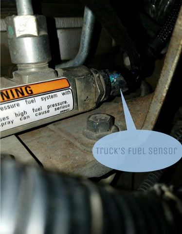
- Auditory Check: Turn the key to RUN (do not start). Listen near the fuel tank. You should hear a hum for 2-3 seconds as the system primes. Silence suggests a failure.
- Voltage Check: Using a multimeter, check for voltage at Fuse #42 (Diesel) or the relevant fuse for the fuel pump circuit. However, since the relay is upstream of the pump, often the best test is to measure voltage at the fuel pump connector itself.
- Swap Test (Impossible): Unlike older trucks, you cannot swap the “Horn Relay” with the “Fuel Pump Relay” because they are internal.
Repair and Bypass Solutions
Since a new TIPM is costly, several workaround solutions have been engineered by the aftermarket.
The TIPM Bypass Cable
This is the most popular emergency fix. It utilizes the external fuse slots to bypass the internal relay.
- Mechanism: A custom cable connects a fuse slot that has power (like the Cigarette Lighter Fuse #40 or Console Fuse #1) directly to the output side of the fuel pump circuit (often accessed via a specific fuse slot related to the pump or an empty slot that taps into the rail).
- Pros: Inexpensive, requires no tools, immediate fix.
- Cons: If connected to a “Battery Feed” fuse, the fuel pump will run continuously unless the cable is removed. It is safer to use an ignition-switched source.
External Relay Conversion
This is a permanent repair that involves cutting the wire harness.
- Procedure: The wire exiting the TIPM that feeds the fuel pump is cut. A standard automotive relay is installed externally. The trigger for this new relay is tapped from an ignition-switched fuse (like the Run/Start logic).
- Pros: Solves the problem permanently using replaceable parts.
- Cons: Requires cutting factory wiring, which some owners are hesitant to do.
TIPM Rebuilding
Services like Circuit Board Medics or Maks Enterprises offer to rebuild the unit.
- Procedure: The owner removes the TIPM and ships it to the facility. The board is removed, the faulty NEC/Omron relay is desoldered, and a new, often higher-amperage relay is soldered in place.
- Pros: Retains factory look and function; no wire cutting.
- Cons: Vehicle is down for several days during shipping.
TIPM Removal and Installation Guide
Replacing the TIPM is a straightforward mechanical task, but it requires adherence to specific electrical safety protocols to avoid damaging the new unit or the vehicle’s ECM.
Tools Required
- 10mm Socket (Battery Terminals)
- 13mm Socket (TIPM Power Stud)
- Flathead Screwdriver (Clip release)
- Socket Wrench
Step-by-Step Procedure
- Safety First: Disconnect the Negative (-) battery cable. Then disconnect the Positive (+) cable. Isolate both cables to ensure they cannot spring back and touch the terminals.
- Power Feed Removal: Open the TIPM lid. Locate the heavy-gauge positive cable connected to the stud on the corner of the unit. Remove the 13mm nut and lift the cable off.
- Release the Unit: Depress the plastic retention tabs that hold the TIPM to its mounting bracket. Lift the unit gently to expose the connectors underneath.
- Disconnect Harnesses: The TIPM has multiple large connectors on the bottom (typically 5 to 7 depending on options).
- Unlock: Each connector has a gray or colored locking lever. Rotate the lever to the “Open” position. This action mechanically ejects the connector from the socket.
- Remove: Pull the connector straight down. Note: The connectors are keyed and color-coded (Green, Gray, Black, White, etc.) so they cannot be plugged into the wrong slot.
- Installation: Comparison of the new unit to the old is vital. Ensure the part numbers match.
- Reconnect: Plug the harness connectors into the new TIPM. Rotate the locking levers to draw the plugs in tight.
- Mount: Snap the TIPM back into the bracket.
- Power: Reattach the main power cable and the 13mm nut.
- Battery: Reconnect Positive first, then Negative.
The “Hard Reset” Procedure
After installation, or when troubleshooting “ghost” electrical gremlins, a Hard Reset is required to force the TIPM to re-learn the vehicle configuration.
- Disconnect both battery cables.
- Discharge: Touch the Negative and Positive vehicle cables together (away from the battery!) and hold them for 10 minutes. This shorts the system capacitance, draining all residual voltage from the modules.
- Reconnect the battery.
- Initialization: Turn the ignition key to the “RUN” position and wait 12 seconds. Do not start the engine yet. This allows the TIPM to handshake with the ECM and CCN to verify the VIN and options.
Troubleshooting “Poltergeist” Issues
The TIPM is susceptible to logic corruption where it behaves erratically.
- Symptoms: Wipers activating randomly, horn honking, door locks cycling, or one headlight refusing to work despite a good bulb.
- The “Short Circuit” Counter: The TIPM monitors current to bulbs. If it detects a short (e.g., from a bad bulb or wiring), it shuts off the circuit. It has a counter for how many times it attempts to reset. If this counter limit is reached, the circuit is permanently disabled until a scan tool is used to reset the module.
- Headlight Fix: If a headlight is out and the fuse/bulb are good, try the “Soft Reset” (Key On/Off cycling) or the “Hard Reset” (Battery Disconnect). If these fail, the driver chip inside the TIPM may be blown.
Towing Electrical Analysis
For owners using the 2006 Ram for towing, the TIPM manages the 7-way connector logic.
| Pin | Function | Fuse | Wire Color |
| 1 | Ground | N/A | White |
| 2 | Trailer Brakes | Fuse 12 (30A) | Blue |
| 3 | Tail / Running Lights | Fuse 15 & 19 | Brown |
| 4 | Battery Charge (+12V) | Fuse 19 (30A) | Black/Red |
| 5 | Left Turn / Stop | Fuse 14 (15A) | Yellow |
| 6 | Right Turn / Stop | Fuse 16 (15A) | Green |
| 7 | Reverse / Aux | Relay Controlled | Purple |
Common Failure: The “Trailer Brake” message on the dash often points to a blown Fuse 12. This is a J-Case fuse. Owners should keep a spare 30A Pink J-Case fuse in the glovebox, as this is a specific part not always available at small gas stations.
Conclusion
The 2006 Dodge Ram’s electrical system, centered around the Totally Integrated Power Module, represents a transition era in automotive engineering. It offers the precision of digital control but burdens the owner with the complexity of integrated circuits and non-serviceable relays. The absence of an interior fuse box is the first hurdle; the potential for fuel pump relay failure is the second.
However, with a clear understanding of the TIPM layout, the correct identification of Mini and J-Case fuses, and the knowledge of bypass strategies for the internal relays, the 2006 Ram remains a highly capable machine. Maintenance of this system requires a shift in mindset from “replacing a fuse” to “managing a module,” but armed with this guide, owners can effectively diagnose and repair their vehicles, ensuring that the legendary powertrains of this generation are not silenced by a simple electrical switch.
Frequently Asked Questions (FAQs)
Q: I have looked everywhere inside the cab. Where is the interior fuse box?
A: It does not exist. The 2006 Dodge Ram consolidated all interior and exterior fuses into the single TIPM unit located under the hood on the driver’s side.
Q: My truck cranks but won’t start. I checked all the fuses and they are fine. What is it?
A: This is the classic symptom of a failed internal fuel pump relay within the TIPM. Since the relay is soldered to the board, you cannot see if it is “blown.” You need to test for voltage at the fuel pump or try a bypass cable solution.
Q: Which fuse controls the cigarette lighter?
A: Fuse #40 (20 Amp Yellow Mini Fuse) controls the cigarette lighter. Fuse #1 (20 Amp Yellow) controls the console power outlet, and Fuse #38 (20 Amp Yellow) controls the dash power outlet.
Q: What is the difference between a Mini Fuse and a J-Case Fuse?
A: A Mini Fuse is small with two blade prongs, used for lower power items (radio, lights). A J-Case Fuse is a larger, box-shaped cartridge fuse used for high-power items (trailer brakes, ABS pump). They are not interchangeable.
Q: Can I drive with a TIPM Bypass Cable installed?
A: Yes, thousands of owners do. However, it is recommended as a temporary solution. A proper repair involves replacing the relay or the TIPM to restore the factory safety protocols.
Q: Why does my left headlight not work even though I changed the bulb?
A: The TIPM may have disabled the circuit due to a detected fault. Try disconnecting the battery for 10 minutes (Hard Reset) to clear the memory. If it persists, the internal driver in the TIPM may have failed.