2006 GMC Sierra Brake Line Diagram: Proper Routing 2026

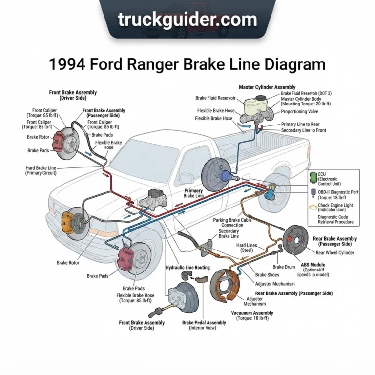
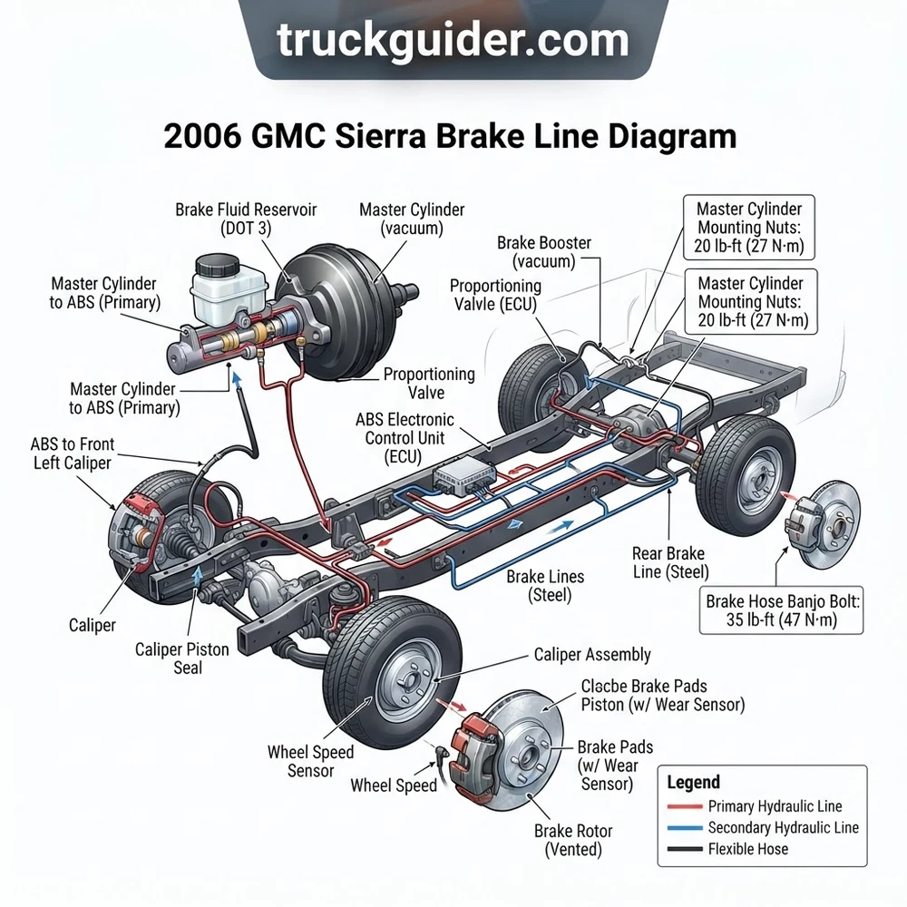
The 2006 GMC Sierra brake line diagram routes primary and secondary lines from the master cylinder down to the ABS module on the inner left frame rail. From the ABS unit, two 3/16-inch lines feed the front calipers, while a single 1/4-inch line runs along the chassis to the rear axle brake hose junction.
📌 Key Takeaways
- Primary master cylinder ports use 1/2-20 and 7/16-24 fittings feeding 1/4-inch and 3/16-inch lines.
- The ABS/EBCM assembly is mounted along the driver-side frame rail beneath the cab floor.
- Flare fittings require a strict torque spec of 12 to 15 lb-ft to prevent thread galling and leaks.
- The most common failure point is severe rust perforation along the frame rail under the driver seat.
- Seek professional service if an ABS automated bleed requiring a bidirectional OBD-II scanner is necessary.
The 2006 GMC Sierra 1500, 2500HD, and 3500 pickup trucks built on General Motors’ GMT800 platform utilize a split hydraulic brake circuit configured to deliver balanced hydraulic clamping force under varying payload conditions. Tracing the hydraulic routing on these trucks is notoriously demanding due to the dense chassis packaging around the left frame rail, transmission bellhousing, and fuel tank. Whether you are dealing with catastrophic line degradation caused by road brine or troubleshooting a low brake pedal after an actuator overhaul, understanding the hydraulic schematics and port orientations of the Brake Pressure Modulator Valve (BPMV) is critical for completing a safe, factory-spec repair.
—
2006 GMC Sierra Brake Line Diagram: Hydraulic System Routing
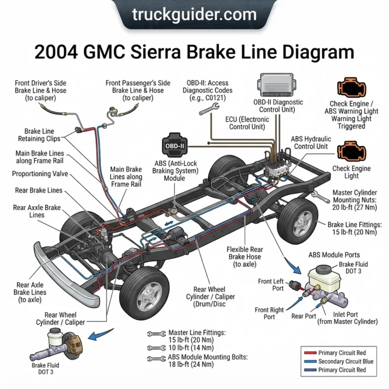
Tracing the complete hydraulic circuit requires following two primary feed lines from the master cylinder down to the chassis-mounted ABS assembly, where fluid is split and metered out to individual wheel circuits. On the 2006 GMC Sierra, the master cylinder reservoir supplies fluid to two distinct chambers: the primary (rearward) piston, which governs front hydraulic circuits, and the secondary (forward) piston, which provides line pressure for the rear axle.


Both lines drop vertically from the master cylinder down along the inner firewall and transition along the top edge of the driver-side hydroformed frame rail. They terminate directly at the Brake Pressure Modulator Valve (BPMV), which is joined to the Electronic Brake Control Module (EBCM). This entire electro-hydraulic assembly is bolted to the inside of the left frame rail directly beneath the driver-side cab floor.
The BPMV features six primary threaded ports. The two inlet ports receive pressurized fluid from the master cylinder, while the four exit ports route regulated hydraulic pressure to the corners of the vehicle. Port identification is stamped directly into the aluminum valve body casting adjacent to each threaded seat:
| BPMV Port Stamping | Circuit Destination | Tubing Outer Diameter | Thread Pitch & Flare Style | Chassis Routing Path |
|---|---|---|---|---|
| MC1 (Secondary) | Inlet from Forward MC Reservoir | 1/4 in (6.35 mm) | M12 x 1.0 ISO Bubble Flare | Firewall down to inner left frame rail bracket. |
| MC2 (Primary) | Inlet from Rearward MC Reservoir | 1/4 in (6.35 mm) | M14 x 1.5 ISO Bubble Flare | Parallels MC1 along firewall to ABS bracket. |
| LF | Left Front Brake Hardline | 3/16 in (4.76 mm) | M10 x 1.0 Inverted Double Flare | Runs forward along inner frame rail to left wheel arch hose. |
| RF | Right Front Caliper Supply | 3/16 in (4.76 mm) | M10 x 1.0 Inverted Double Flare | Crosses front engine crossmember under oil pan to passenger side. |
| LR | Left Rear Caliper (or 3-Channel Feed) | 1/4 in (6.35 mm) | M12 x 1.0 Inverted Double Flare | Runs aft down left frame rail, passes fuel tank to axle drop hose. |
| RR | Right Rear Caliper (4-Channel JL4 Option) | 1/4 in or 3/16 in | M12 x 1.0 or M10 x 1.0 Inverted | Dedicated feed run on RPO JL4/Active Brake Control models. |
On standard 3-channel ABS configurations (RPO JM9 or JH6 without StabiliTrak), a single 1/4-inch hardline exits the BPMV and routes rearward past the transmission support crossmember and fuel tank. At the crossmember directly forward of the rear differential, this line transitions into a flexible DOT-approved drop hose. The hose terminates at an axle-mounted distribution tee block, dividing into two independent 3/16-inch hard lines that run across the axle tubes to the left and right rear calipers.
On 2006 Sierra models equipped with StabiliTrak (RPO JL4), the ABS BPMV operates as a 4-channel system. Do not install a 3-channel intermediate rear line on a JL4 truck; 4-channel architectures run two discrete lines down the frame rail to independently control rear wheel slip during yaw adjustments initiated by the Electronic Brake Control Module.
—
Tubing Specs and Flare Styles: NiCopp vs Stainless Steel Lines
Replacing rusted GMT800 hardlines requires close attention to the flared ends. General Motors mixed both SAE 45-degree inverted double flares and ISO/DIN metric bubble flares on the 2006 Sierra braking system. Connecting an inverted double flare into an ISO bubble seat will crush the flare lip unevenly, causing high-pressure fluid blowouts under panic-stop hydraulic spikes exceeding 1,800 PSI.


The master cylinder ports and the BPMV primary feed ports utilize ISO bubble flares with metric male tube nuts (M12x1.0 and M14x1.5). Conversely, the exit ports delivering fluid to the front flex hoses and the intermediate rear junction utilize SAE standard inverted flares, frequently utilizing an M10x1.0 thread with an inverted cone seat.
When replacing line sets, technicians must decide between pre-bent stainless steel line kits and bulk copper-nickel (NiCopp) alloy coils.
| Specification / Metric | Pre-Bent 304 Stainless Steel Kits | Bulk Copper-Nickel (NiCopp / Cunifer) |
|---|---|---|
| Material Composition | ASTM A269 Grade 304 Austenitic Stainless | 90% Copper, 10% Nickel (UNS C70600) |
| Corrosion Resistance | Permanent; impervious to magnesium/calcium chloride | Extremely High; forms protective oxide patina |
| Malleability & Routing | Extremely rigid; rigid bends complicate snaking around cab mounts | High ductility; easily hand-bent around chassis obstructions |
| Flare Seat Sealing | Demands high torque spec to crush; prone to port weepage | Malleable flare conforms instantly to brass/aluminum ports |
| Burst Pressure Rating | > 12,000 PSI (3/16 in OD, 0.028 in wall) | > 8,500 PSI (3/16 in OD, 0.028 in wall) |
| Installation Labor | High; frequently requires unbolting cab or lifting bed | Moderate; can be fished through tight frame gaps |
Pre-bent stainless steel line kits provide an exact factory aesthetic and permanent corrosion resistance. However, their rigidity makes installation exceptionally difficult on an assembled vehicle. Snaking the long rear hardline past the front left cab mount and fuel tank without lifting the truck bed or dropping the tank is almost impossible with rigid stainless. Furthermore, stainless steel work-hardens quickly. If an inverted flare fails to seat properly against the BPMV seat, you cannot easily tighten past the recommended torque spec without risking stripped threads in the aluminum modulator housing.


Copper-nickel (NiCopp) tubing is the preferred solution for working mechanics on the GMT800 chassis. Meeting SAE standard J1047 and ISO 4038, NiCopp features an 8,500+ PSI burst strength—vastly exceeding maximum master cylinder hydraulic output (1,500–2,000 PSI under emergency threshold braking). Its malleability lets you route lines past bottlenecks along the frame rail, and the flare face deforms predictably under nominal torque specs to seal instantly without damaging female seat threads.
Factory torque spec for M10x1.0 and M12x1.0 brake hardline tube nuts threaded into the aluminum BPMV body is 18 N·m (13 lb-ft / 159 lb-in). Master cylinder tube nuts should be torqued to 19 N·m (14 lb-ft). Over-tightening will gall or crack the internal tapered seat of the ABS module.
—
2006 Sierra Brake Line Failure Symptoms and GMT800 Rust Spots
The factory lines on the 2006 Sierra were fabricated from low-carbon steel wrapped in a zinc-fluoroplastic or nylon coating. On the GMT800 platform, road moisture, debris, and chemical de-icers become trapped between the outer protective coating and the steel wall. This traps brine against the metal and drives severe localized galvanic corrosion, completely hidden beneath an apparently intact nylon sheath.
Critical Rust Hotspots on the GMT800 Frame
1. The BPMV Cluster Zone: Located beneath the driver-side door on the inside web of the frame rail. Five to six lines run in tight plastic retention clips. Road mud thrown by the front left tire accumulates directly inside these clips, corroding all lines simultaneously right at the flare nuts.
2. The Fuel Tank Bottleneck: The rear main brake hardline routes through an inaccessible 1/2-inch gap between the steel frame rail and the inboard-mounted polyethylene fuel tank. Trapped silt remains permanently damp in this channel, causing the rear line to perforate unseen above the tank sending unit.
3. The Engine Crossmember Run: The right-front crossover hardline drops under the harmonic balancer and steering rack along the front tubular crossmember. Exposure to stone chips and corrosive fluids (such as acidic leaks when inspecting overall engine bay health, such as steering fluid or minor overflow from the radiator coolant flow channels) causes this line to perforate at its lowest structural bend.
4. The Axle Junction Drop: The intermediate hardline terminates in an open-air bracket ahead of the rear coil/leaf spring mount, where suspension articulation constantly flexes the interface between the hardline and flexible hose.
Warning Signs of Hydraulic Failure
The primary warning sign of structural brake line compromise is a progressive or sudden collapse in pedal travel. During normal operation, the hydraulic system maintains zero compressible volume. When line oxidation thins the steel wall, high brake pressure expands the pipe wall elasticity (causing a spongy pedal feel) before ultimately bursting.


When a line ruptures, the brake pedal drops directly to the floorboard with negligible resistance until the master cylinder’s secondary piston mechanically contacts the primary piston bore. At this point, the mechanical stroke activates the internal brake differential pressure switch. This illuminates the red BRAKE warning light on the instrument cluster.
Unlike general powertrain warnings where a check engine light alerts you to an emissions fault or ignition misfire, the red brake lamp signals an immediate loss of hydraulic circuit integrity that demands an instant shutdown of vehicle operation.
—
Diagnosing Hydraulic Pressure Loss and OBD-II ABS Diagnostic Codes
When troubleshooting low line pressure or pedal sink on a 2006 Sierra, you must methodically distinguish between external hardline leaks, internal master cylinder seal bypassing, and internal BPMV valve leakage. Follow this systematic diagnostic sequence:
Step 1: Static Hydraulic Hold-Off and Leakdown Isolation
Top off the master cylinder with clean fluid. Apply steady, moderate foot pressure (approximately 50 lbs of force) to the brake pedal with the engine off to deplete vacuum from the brake booster. Hold the pedal for 60 seconds. If the pedal steadily creeps downward toward the floorboard:
Inspect all five frame rail line runs with a high-intensity light for wetness or dripping.
If no external leaks appear along the lines, caliper pistons, or drum wheel cylinders, the fault is isolated to internal fluid bypassing past the master cylinder primary/secondary piston seals, or an unseated ABS internal dump valve.
Step 2: Mechanical Fluid Isolation Using Port Plugs
To confirm whether the leak is downstream of the master cylinder or within the master cylinder itself, disconnect the two outlet lines (MC1 and MC2) at the master cylinder. Thread steel inverted flare/bubble test plugs directly into the ports. Apply pedal pressure:
If the pedal is rock-hard and will not move more than 1/4 inch, the master cylinder is fully intact.
Reconnect the lines to the BPMV and install test plugs into the BPMV outlet ports (LF, RF, LR, RR). If pedal creep reappears, an internal accumulator valve or return pump check-valve inside the BPMV is mechanically jammed open with debris, shunting hydraulic pressure back to the low-pressure reservoir.
Step 3: Interrogating the EBCM via the OBD-II Port
Connect an advanced bi-directional scan tool to the 16-pin OBD-II diagnostic link connector (DLC) under the driver-side dashboard. While standard powertrain scanners only read emissions-related DTCs from the engine ECU (such as sensor faults or timing anomalies), a full-function diagnostic platform must establish serial data communication with the Electronic Brake Control Module (EBCM).
Scan for chassis-specific “C” series diagnostic code faults:
DTC C0265 or C0267: EBCM internal motor relay circuit open or shorted. Frequently indicates cracked solder pads on the internal EBCM printed circuit board (a widespread GMT800 failure mode).
DTC C0035 / C0040: Left or Right Front Wheel Speed Sensor circuit malfunctions. While these speed sensor faults do not directly drop line pressure, erratic speed signals trigger false ABS activation (“chatter”) at speeds below 10 MPH, mimicking a broken line by rapidly opening the pressure release valves.
DTC C0221: Right front wheel speed sensor circuit open.
DTC C0281: Brake switch circuit failure, impeding proper valve cycling commands.
Unlike engine monitoring tasks—such as tracking mechanical cam wear through a slack timing chain or confirming engine lubrication limits via live oil pressure gauges—braking diagnostics require verifying both raw mechanical line integrity and electronic valve solenoid actuation.
Do not drive the vehicle if the red hydraulic BRAKE lamp remains lit, even if the scan tool reports no active ABS codes. The dash light confirms either low reservoir fluid level or an actuated differential switch, indicating a hydraulic pressure imbalance of 300+ PSI between the front and rear split systems.
—
2006 GMC Sierra Brake Line Replacement and Automated ABS Bleeding
Replacing brake lines on a GMT800 platform requires careful routing and a complete automated hydraulic bleed. Use the following technician-proven sequence to replace failed lines and restore pedal firmness:
Clear Pathing and Evacuation: Siphon all degraded fluid from the master cylinder reservoir. Spray all BPMV line fittings, caliper bleeder screws, and frame retention clips generously with penetrating fluid 24 hours prior to removal.
Frame Rail Access (Bed Lifting Shortcut): When installing the long rear hardline, you do not need to drop the fuel tank. Instead, remove the four 18mm bolts securing the driver side of the truck bed, loosen the passenger-side bolts, and jack up the driver side of the bed 4 to 6 inches, securing it on wooden blocks. This clears a direct, unobstructed channel across the top of the frame rail to slide a pre-flared, continuous copper-nickel line directly past the fuel tank.
Thread Engagement into Aluminum Modulator: Always thread every brake line nut into the BPMV ports by hand for a minimum of 4 complete turns before applying a flare nut wrench. The internal threads in the aluminum modulator housing strip easily; cross-threading the housing ruins the entire ABS block. Tighten all 3/16-inch lines to 18 N·m (13 lb-ft) and 1/4-inch lines to 19 N·m (14 lb-ft).
Bench Bleeding the Master Cylinder: If the master cylinder reservoir ran dry at any point during line installation, you must bench-bleed it prior to connecting the brake lines. Mount the unit level in a vise, route plastic return tubes from the outlet ports back into the reservoir, and slowly cycle the piston using a smooth drift punch until all expelled air bubbles cease.
System Fill and Wheel Bleed Pattern: Fill the reservoir exclusively with fresh, dry DOT 3 brake fluid from a sealed container. Perform an initial gravity or manual bleed at all four corners to re-establish baseline hydraulic volume. Always follow the GM factory bleeding sequence to purge air systematically through the cross-split circuits:
1. Right Rear (furthest hydraulic path from the BPMV)
2. Left Rear
3. Right Front
4. Left Front (shortest hydraulic path)
Executing the Automated ABS Bleed: Air inevitably becomes trapped inside the internal BPMV accumulator bores and normally closed dump valves whenever lines are detached. Standard pedal pumping cannot evacuate this trapped air. Connect an advanced bi-directional scan tool to the OBD-II port:
1. Access: Diagnostics > Chassis > ABS/TCS > Special Functions > Automated Bleed.
2. Maintain 40–50 lbs of foot pressure on the brake pedal when prompted.
3. Command the test. The scan tool will energize the internal ABS pump motor and pulse the internal inlet and outlet solenoids sequentially for approximately 60 seconds, forcing trapped air bubbles out of the internal BPMV accumulators and into the downstream hardlines.
4. Repeat the manual 4-corner wheel bleed (RR, LR, RF, LF) to purge the newly released air pockets out through the caliper bleeder screws. Repeat this automated cycle until the brake pedal is rock-solid.
—
2006 GMC Sierra Brake Line Diagram Technical FAQ
What are the exact brake line and fitting sizes used on a 2006 GMC Sierra?
The 2006 Sierra uses a mix of tubing diameters and fitting threads:
Primary Feed Lines (Master Cylinder to BPMV): 1/4-inch OD tubing. The forward port uses an M12x1.0 bubble flare nut; the rearward port uses an M14x1.5 bubble flare nut.
Front Wheel Hardlines: 3/16-inch OD tubing utilizing M10x1.0 standard inverted double flare nuts.
Rear Main Feed Line: 1/4-inch OD tubing running from the BPMV (M12x1.0 inverted flare) back to the rear flex hose drop.
Rear Axle Tube Lines: 3/16-inch OD tubing utilizing 3/8-24 or M10x1.0 inverted double flare nuts connecting the distribution tee block to the rear wheel brake assemblies.
Can you bleed the ABS system on a 2006 Sierra without an OBD-II scan tool?
You can bleed the base mechanical hydraulic lines without a scan tool using pressure, vacuum, or manual two-person pedal methods. However, if air has entered the internal BPMV valve body (such as when the master cylinder drains completely or the ABS unit is disconnected), a scan tool with an automated bleed function is necessary. The internal accumulator chambers and dump solenoids are normally closed; only an electronic command from a bi-directional scan tool can open these internal passages to force trapped air out into the service circuits.
Alternatively, some mechanics cycle the valves by safely triggering ABS stops on a low-friction surface (such as a gravel road) followed by a manual re-bleed, though this method is far less consistent than an automated bleed.
Why does my brake pedal stay soft after replacing all rusted lines and bleeding?
A persistent spongy pedal after a complete line replacement typically stems from one of three issues:
1. Trapped Air in the ABS Unit: Air remains locked inside the BPMV accumulator valves. This requires cycling the module with an automated bleed routine via a scan tool.
2. Master Cylinder Piston Seal Blowby: If the pedal was pumped fully to the floor during manual bleeding, the master cylinder piston seals were pushed through an unused portion of the bore that often contains rust and abrasive sludge. This can tear the delicate rubber primary piston cups, allowing fluid to bypass internally.
3. Improper Flare Seating: Stainless steel lines that were not torqued sufficiently can allow air to be drawn back into the system during pedal release without showing noticeable outward fluid leaks.
How does the ABS EBCM interact with the vehicle ECU during a braking event?
The Electronic Brake Control Module (EBCM) continuously communicates with the Powertrain Control Module / Engine Control Unit (ECU) over the vehicle’s GM Class 2 Serial Data bus. During an ABS stop, traction control event, or stability intervention (on StabiliTrak trucks), the EBCM evaluates wheel deceleration rates against vehicle speed.
If wheel slip exceeds safe limits, the EBCM commands the ECU to retard ignition timing and scale back electronic throttle opening to reduce wheel spin, while simultaneously cycling the BPMV pulse solenoids to balance hydraulic clamping force at the calipers.
What are the caliper bleeder screw torque specs on a 2006 Sierra?
Factory torque specs for the front caliper bleeder screws are 17–24 N·m (13–18 lb-ft). Rear disc brake bleeder screws (on trucks equipped with rear disc brakes under RPO JH6) require 12–16 N·m (106–141 lb-in). Avoid over-torquing the bleeder screws, as the hollow hex fittings can sheer off inside the cast iron caliper bodies. Use a dedicated 6-point flare nut or box wrench when servicing these fittings.
Step-by-Step Guide to Understanding the 2006 Gmc Sierra Brake Line Diagram


Identify – Match each line on the vehicle against the diagram to differentiate front left, front right, and rear circuits.
Locate – Find the ABS module bracket along the inner driver-side frame rail directly below the cab door sill.
Reference – Trace the primary and secondary feed paths from the master cylinder down into ports MC1 and MC2 on the schematic.
Connect/Route – Bend and thread replacement lines into their respective ports, fastening flare nuts to the factory torque spec of 14 lb-ft.
Verify – Pressure test the hydraulic system and inspect every fitting for leaks while an assistant firmly depresses the brake pedal.
Troubleshoot – Connect an OBD-II scanner to clear any ABS or check engine light faults, then execute a scan for remaining trouble codes.
2006 Gmc Sierra Brake Line Diagram: Frequently Asked Questions


What does the 2006 gmc sierra brake line diagram show?
The schematic outlines complete hydraulic routing from the dual-reservoir master cylinder into the frame-mounted ABS hydraulic control unit. It displays individual hard line pathways branching to both front brake calipers and the rear proportioning block, detailing standard inverted double flares and ISO metric bubble flare connections across the chassis.
How do I read the 2006 gmc sierra brake line diagram?
Trace hydraulic flow starting at the master cylinder ports marked primary and secondary. Follow each line downward to the designated ABS pump ports labeled MC1 and MC2. Then, follow outbound lines marked LF, RF, and RR/LR to their corresponding flexible rubber caliper hoses and frame bracket retaining clips.
What are the main components in 2006 gmc sierra brake line diagram?
Key components include the vacuum brake booster, dual-chamber master cylinder, hydraulic control unit (integrated with the ABS module and ECU), flexible reinforced rubber caliper hoses, frame bracket retainers, bleeder screws, and the pre-bent steel or nickel-copper hard lines extending along the frame rail to the rear axle tee.
What are common problems with 2006 gmc sierra brake line diagram?
Typical problems involve road salt corrosion causing sudden hydraulic blowouts along the driver-side frame rail. A spongy pedal indicates trapped air, while internal line collapsed rubber hoses cause uneven brake drag. An illuminated check engine light or ABS indicator accompanied by a diagnostic code often signals low pressure or wheel-speed variance.
Can I use 2006 gmc sierra brake line diagram for DIY repair?
Yes, it provides essential routing geometry for replacing rusted factory steel lines with corrosion-resistant pre-bent or flexible copper-nickel (NiCopp) lines. However, completely dry systems require an advanced OBD-II scan tool capable of running an ABS automated bleed cycle to evacuate trapped air bubbles from the internal pump valves.
What tools do I need for 2006 gmc sierra brake line diagram?
You need standard flare nut wrenches (10mm, 11mm, 13mm, and 14mm), a double-flaring kit, tubing bender, line cutter, penetrating oil, catch basin, and DOT 3 brake fluid. An OBD-II diagnostic scan tool is also recommended to clear any persistent diagnostic code and initiate computerized ABS bleeding procedures properly.