2007 Chevy Silverado Brake Line Diagram: Proper Routing 2026

The 2007 Chevy Silverado brake lines route from the master cylinder down to the ABS module mounted on the inside left frame rail below the driver’s seat. From the ABS block, individual 1/4-inch and 3/16-inch steel lines feed the front calipers and run along the driver-side chassis rail to the rear axle junction block.
📌 Key Takeaways
- Master cylinder primary/secondary ports use metric bubble flares, while standard line sections use M10x1.0 or M12x1.0 threaded inverted flare fittings.
- The ABS Electronic Brake Control Module (EBCM) splits flow into four circuits along the driver-side inner frame rail.
- Always torque tube nut fittings to the factory torque spec of 14 lb-ft (19 Nm) to prevent stripped threads or fluid leaks.
- Severe corrosion along the driver-side frame rail crossmember is the primary failure point for factory nylon-coated steel lines.
- Flushing and ABS automated bleeding requires an OBD-II bi-directional scan tool; consult a professional if pedal travel remains spongy.
The 2007 model year represents a critical transition point for General Motors full-size trucks. Chevrolet produced two distinct platforms under the same model year designation: the carryover GMT800 platform (badged as the 2007 Silverado Classic) and the redesigned GMT900 platform (the “New Body Style” Silverado). Understanding the hydraulic routing, flare geometry, fitting threads, and control module positioning requires identifying which platform chassis you are servicing. This technical guide delivers the complete hydraulic architecture, routing schematics, material specifications, and repair procedures for the hydraulic brake lines on both variations of the 2007 Chevrolet Silverado 1500, 2500HD, and 3500 series trucks.
High-resolution schematic illustrating the 2007 Chevy Silverado brake line layout: Master cylinder tandem circuits, EBCM/BPMV valve port locations, front wheel feed routing, frame rail channel pass-through, rear axle tee-block junction, and caliper flexible drop hoses.
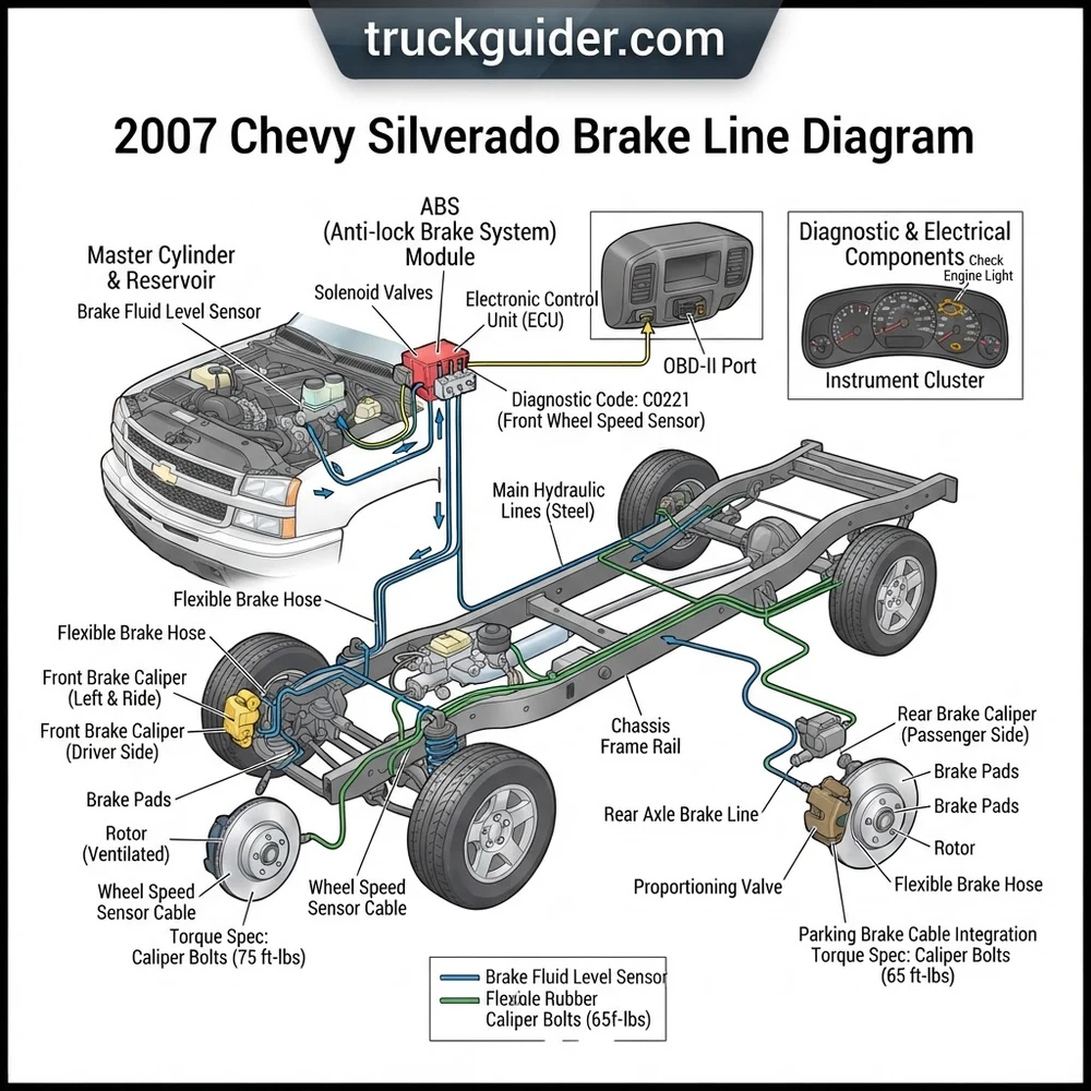
2007 Chevy Silverado Brake Line Diagram and Hydraulic Routing


The hydraulic system of the 2007 Chevrolet Silverado utilizes a split, diagonally independent or front-to-rear split dual-circuit hydraulic configuration managed by an electro-hydraulic control unit. Braking force originates at the tandem-bore master cylinder, mounted directly to the vacuum booster or hydro-boost assembly on the driver-side firewall. The master cylinder reservoir supplies DOT 3 fluid to dual internal chambers. The primary piston serves the front brake circuits, while the secondary piston provides hydraulic displacement for the rear brake assemblies.



Exiting the master cylinder, two dedicated intermediate lines route downward along the driver-side inner fender sheet metal. On both GMT800 and GMT900 chassis, these lines feed directly into the top or side ports of the Brake Pressure Modulator Valve (BPMV), which is joined directly to the Electronic Brake Control Module (EBCM). On the 2007 Classic (GMT800), the BPMV/EBCM assembly resides along the inside of the left frame rail, directly beneath the driver-side floor pan. On the 2007 New Body Style (GMT900), GM relocated this assembly further forward on the driver-side frame rail apron, adjacent to the engine compartment steering intermediate shaft, improving accessibility and shielding it from excessive rearward road debris.
When routing intermediate lines near the engine bay, maintain a minimum clearance of 50 mm (2.0 inches) from exhaust manifolds and steering shafts. If servicing powertrain systems, such as tracing auxiliary coolant flow paths to the heater core or servicing an engine timing chain, ensure line brackets along the frame horns remain anchored to prevent vibrational metal fatigue.
From the ABS Hydraulic Modulator (BPMV), four primary output channels branch across the vehicle chassis:
- Left Front Hard Line: This line exits the BPMV and executes a short run forward along the upper edge of the frame rail before terminating at the driver-side front wheelhouse bracket, adapting into a reinforced flexible rubber hose coupled to the dual-piston front caliper via a 10 mm banjo fitting.
- Right Front Hard Line: Exiting the modulator, this tube routes downward to the front crossmember (underneath the radiator core support and front engine oil pan), transversing the frame laterally to the passenger-side wheelhouse. It is shielded by heat-resistant conduit where it routes beneath powertrain components.
- Rear Main Feed Line: A single continuous line exits the rear delivery port of the modulator block, traversing rearward along the web of the driver-side hydroformed steel frame channel. It routes between the frame and the exterior flank of the 26- or 34-gallon fuel tank.
- Rear Axle Split: The rear main line terminates at a heavy-duty bracket mounted atop the crossmember just forward of the rear differential housing. It threads into a flex hose that bridges the frame to the axle casing, terminating at a brass junction block (T-fitting) welded or bolted to the axle tube. From this junction, twin steel tubes branch laterally across the left and right axle tubes to feed the rear drum or disc brake calipers.
GMT800 Classic vs GMT900 Brake Line Specs and Flare Standards


Correctly identifying the hardware differences between the 2007 Classic and the 2007 New Body Style is critical before cutting tubing or ordering fittings. The GMT800 platform relies heavily on an unusual hybrid mixture of metric threads with ISO bubble flares alongside imperial threads with SAE 45-degree inverted double flares. Installing an SAE double flare into an ISO metric bubble port will deform the seat, causing rapid fluid pressure loss under panic braking.
| Chassis Platform | Line Section / Circuit | Tube Outer Diameter | Thread Size & Pitch | Required Flare Standard |
|---|---|---|---|---|
| 2007 Classic (GMT800) | Master Cylinder Primary | 1/4 in (6.35 mm) | M12 x 1.0 | ISO / Bubble Flare |
| 2007 Classic (GMT800) | Master Cylinder Secondary | 1/4 in (6.35 mm) | M11 x 1.5 (or M12 x 1.0) | ISO / Bubble Flare |
| 2007 Classic (GMT800) | BPMV to Front Left / Right | 3/16 in (4.76 mm) | M10 x 1.0 / M12 x 1.0 | ISO / Bubble Flare |
| 2007 Classic (GMT800) | BPMV to Rear Axle Feed | 1/4 in (6.35 mm) | M14 x 1.5 or 1/2-20 Inverted | Varies (Bubble / Double) |
| 2007 New Body (GMT900) | Master Cylinder to BPMV (Both) | 1/4 in (6.35 mm) | M12 x 1.0 | ISO / Bubble Flare |
| 2007 New Body (GMT900) | Front Left / Right Drops | 3/16 in (4.76 mm) | M10 x 1.0 | ISO / Bubble Flare |
| 2007 New Body (GMT900) | Rear Main Intermediate | 1/4 in (6.35 mm) | M12 x 1.0 | ISO / Bubble Flare |
| 2007 New Body (GMT900) | Rear Axle Cross Lines | 3/16 in (4.76 mm) | M10 x 1.0 | ISO / Bubble Flare |
When executing line replacements on a 2007 Silverado, raw steel tubing coated in OEM electroplated zinc is obsolete. Professional mechanics utilize two distinct replacement options:
1. Nickel-Copper Alloy (UNS C70600 / NiCopp): Composed of approximately 90% copper, 10% nickel, and trace iron/manganese, this tubing conforms to SAE J1047 and ISO 4038. It will not corrode from road salt exposure, bends easily by hand without kinking, and forms airtight 45-degree double flares and DIN/ISO bubble flares reliably using handheld mechanical flaring yokes.


2. Grade 304 Stainless Steel Pre-Bent Kits: Pre-formed CNC kits duplicate factory bends precisely. While offering maximum tensile strength and complete corrosion immunity, stainless steel line is work-hardened. If you must flare stainless line manually, use a 37-degree AN flaring block or a severe-duty hydraulic flaring press equipped with hardened steel dies. Do not attempt to flare 304 stainless tubing using standard cast-iron DIY clamp sets.
Diagnostic Code Clues and Brake Line Failure Symptoms


Brake line integrity compromises manifest through distinct mechanical symptoms and digital warning states. Because brake fluid is hygroscopic (absorbing atmospheric moisture through reservoir vent ports and microscopic seal clearances), untreated corrosion acts from the inside out, while road salt, brine, and road wash erode the lines externally.
Corrosion on the 2007 Silverado occurs most aggressively in hidden retention pockets: along the driver-side frame rail where road wash packs behind the fuel tank, and directly below the driver-side cab footwell near the EBCM mounting bracket. Complete line blowout under panic braking will lead to catastrophic hydraulic pressure drop.
Pay close attention to these mechanical and electronic failure symptoms:
- The “Long” or Sinking Brake Pedal: A pedal that travels low to the floor before engaging indicates localized line expansion, internal master cylinder bypass, or a pinhole hydraulic breach. If fluid level in the master cylinder reservoir decreases, hydraulic fluid is escaping past line flare seats or rusted wall sections.
- Spongy Resistance Under Static Load: Air introduced through compromised fitting threads or pinhole fissures compresses under line pressure. Unlike brake fluid, air bubbles act as springs within the hydraulic column, preventing full caliper piston advancement.
- Illuminated Dashboard Warning Lamps: A pressure differential switch inside the master cylinder or fluid-level sensor will trip the red BRAKE warning light. Furthermore, if pressure drops abruptly during ABS modulation, the wheel speed sensor data conflicts with internal hydraulic pressure targets, causing the powertrain control network to alert the operator. The driver may see the StabiliTrak off message, the ABS lamp, and occasionally a check engine light illuminated if shared Controller Area Network (CAN) communication signals are interrupted.
- Stored Electronic Brake Control Module (EBCM) Codes: Connecting a professional scanner to the vehicle data link connector reveals distinct fault conditions. A severe loss of line holding pressure or stuck-open modulator valve registers an electronic diagnostic code such as DTC C0265 (EBCM relay circuit malfunction), C0035/C0040 (speed sensor circuit tracking faults during erratic braking lockup), or C0550 (internal electronic control unit diagnostic integrity fault).
If you encounter unexplained wetness along the crossmembers, do not confuse hydraulic fluid with oil residue. During separate mechanical procedures, such as diagnosing oil pressure sensor leaks down the rear of the Vortec engine block, grease can migrate along the frame rail and coat the brake lines, attracting grit that accelerates rust formation.


Tracing Leaks on the 2007 Chevy Silverado Brake Line Diagram


Methodically isolate structural failures across the hydraulic circuit using the following diagnostic procedure. Trace the system systematically from the primary pressure source back to the friction assemblies.
- Examine the Master Cylinder and Booster Interface:
Clean the master cylinder casting using residue-free brake cleaner. Check the output flare nuts at the forward and rearward reservoir ports. Run a gloved finger underneath the junction where the aluminum master cylinder mates to the front vacuum booster shell. Wetness at this seam indicates a ruptured rear internal piston seal, allowing brake fluid to seep into the vacuum canister, stripping the booster diaphragm.
- Inspect the ABS Hydraulic Modulator (BPMV) and Frame Manifold:
Raise the truck safely on a frame-contact lift or heavy-duty jack stands. Locate the BPMV along the driver-side inner frame rail. Clean the valve body, where six distinct lines converge (two inlet lines from the master cylinder and four outlet lines feeding the wheels). Examine the aluminum block ports for galvanic corrosion between the steel tube nuts and aluminum threads. Stress cracking frequently manifests at the flare flare necks entering this block.
- Trace the Driver Frame Web and Hidden Fuel Tank Pocket:
Utilize an inspection mirror and a high-lumen work light to view the primary rear line routing behind the plastic fuel tank. The factory clips secure the 1/4-inch line against the inside frame rail channel. Road debris and salt slurry collect inside these clips, retaining moisture indefinitely. Look for heavy flaking (delamination scale), localized blistering of the nylon protective wrap, and wet residue staining the frame metal.
- Evaluate the Rear Axle Junction Block and Rigid Axle Tubes:
Follow the rear line across the intermediate flex drop down to the rear axle tee fitting. Inspect the brass block mounting bolt for loosening and verify that the distribution tubes branching left and right across the axle housing tubes have not sustained stone-peck punctures or fatigue stress fractures adjacent to the differential cover welds.
- Check Flexible Brake Hoses and Banjo Bolt Sealing Washers:
Flex each rubber drop hose by hand. Inspect the outer neoprene jacket for cracking, dry rot, twisting, or deep abrasion grooves caused by wheel rim interference. Have an assistant depress the brake pedal with the engine running to build maximum line pressure (1,200 to 1,800 PSI); verify that no localized ballooning occurs on the flexible hose body, which signals broken internal reinforcing braids.
OBD-II Scan Tool Bleeding and Line Torque Spec Reference
After installing new hard lines or replacing sections of the hydraulic circuit, traditional manual pump-and-hold bleeding is insufficient if air has entered the ABS Hydraulic Modulator (BPMV). When fluid drains out during line fabrication, air enters the internal valve cavities, accumulator chambers, and normally-closed balance solenoids. These internal air pockets will not purge via gravity or manual pedal pumping.
To purge the system fully, connect a professional-grade bi-directional scan tool to the vehicle OBD-II diagnostic port beneath the steering column. Access the ABS/Chassis menu and select the Automated Bleed Procedure. The ECU and EBCM command the internal motor pump and cycling solenoids to actuate repeatedly in a rapid sequence, purging micro-bubbles from the secondary accumulator circuits directly into the main brake line runners.
Follow the OEM bleeding sequence precisely: (1) Right Rear, (2) Left Rear, (3) Right Front, (4) Left Front. Maintain a continuous reservoir level with clean, fresh DOT 3 fluid throughout the procedure to prevent air ingestion.
Observe strict torque values during reassembly. Over-torquing steel tube nuts into the softer aluminum alloy of the master cylinder casting or the ABS modulator valve block will permanently strip internal threads, ruining the assembly. Conversely, under-torquing will fail to seat the flare against the internal anvil cone, causing slow leaks under high-pressure braking events.


| Fastener / Fitting Location | Thread Dimension | Torque Spec (Foot-Pounds) | Torque Spec (Newton-Meters) |
|---|---|---|---|
| Master Cylinder Tube Nuts (GMT800/GMT900) | M12 x 1.0 | 18 lb-ft | 25 N·m |
| BPMV / ABS Modulator Tube Nuts (3/16″ line) | M10 x 1.0 | 15 lb-ft | 20 N·m |
| BPMV / ABS Modulator Tube Nuts (1/4″ line) | M12 x 1.0 / M14 x 1.5 | 18 lb-ft | 25 N·m |
| Front Caliper Banjo Bolts | M10 x 1.5 | 30 lb-ft | 40 N·m |
| Rear Caliper Banjo Bolts (Disc Rear) | M10 x 1.5 | 30 lb-ft | 40 N·m |
| Caliper Bleeder Screws (Front & Rear) | M10 x 1.5 / 5/16-24 | 106 lb-in (8.8 lb-ft) | 12 N·m |
| Master Cylinder Mounting Nuts (to Booster) | M10 x 1.5 | 27 lb-ft | 36 N·m |
Always replace copper crush washers on caliper banjo connections whenever a hose is unthreaded. Torque each fitting using a calibrated line wrench (flare nut wrench) or a torque adapter set 90 degrees to the wrench drive head to ensure exact clamping force without rounded hex shoulders.
2007 Chevy Silverado Brake Line Diagram FAQ and Troubleshooting
What is the exact rear brake line tube diameter on a 2007 Silverado?


The primary intermediate hard line running from the ABS Hydraulic Modulator (BPMV) back along the frame rail to the rear axle is 1/4-inch (6.35 mm) outer diameter on virtually all 2007 1500 and 2500HD models. Once the line hits the flexible drop hose and connects to the rear axle junction block (tee fitting), the lines that branch across the left and right axle tubes to the wheel assemblies step down to 3/16-inch (4.76 mm) outer diameter.
Can you bend and flare NiCopp tubing without specialty hydraulic flaring tools?
Yes. Nickel-copper alloy tubing (NiCopp / Cunifer) is significantly more ductile than rigid OEM coated carbon steel or work-hardened 304 stainless steel. You can achieve smooth, kink-free chassis contours by hand without external tube benders. Furthermore, high-quality handheld mechanical clamp-and-anvil flaring tools reliably form both 45-degree SAE double inverted flares and ISO metric bubble flares without galling or splitting the tube lip, provided the cut end is reamed, deburred, and chamfered prior to forming.
Why does the brake pedal drop to the floor after bleeding new hard lines?
If you have installed new hard lines, manually bled all four corners, and the pedal continues to drift downward under static foot pressure, air remains trapped inside the secondary circuits of the ABS Hydraulic Modulator. When the lines drained, the EBCM accumulator bores emptied. You must perform an automated ABS bleed cycle using a scan tool communicating through the OBD-II port. This electronically energizes the internal BPMV solenoids, cycling the valves while you apply positive pressure via a pressure bleeder or pedal stroke.
Will an ABS hydraulic leak trigger a check engine light or diagnostic code?


A hydraulic line rupture primarily illuminates the red BRAKE telltale and amber ABS warning light. However, it can indirectly
Do you have to drop the fuel tank to install the rear main hard line?
From the GM assembly plant, the rear main 1/4-inch brake hard line was installed on the bare hydroformed frame rail before the fuel tank, wiring harnesses, and truck cab were lowered onto the chassis. When installing a rigid, one-piece pre-bent replacement line kit (especially stainless steel), you must drop the fuel tank support straps and lower the fuel tank assembly to seat the line inside the factory retention clips. However, if you fabricate the line using flexible NiCopp bulk tubing, you can fish the tubing through the frame rail passage without completely dropping the fuel tank, though lowering the tank 3 to 4 inches significantly improves routing accuracy and prevents chafing against the frame.
Step-by-Step Guide to Understanding the 2007 Chevy Silverado Brake Line Diagram
Identify – Locate the hydraulic circuits, master cylinder feeds, and individual wheel circuits using the brake line schematic.
Locate – Find the ABS module mounted to the inside of the driver-side frame rail directly below the cab floor.
Reference – Match the labeling on the diagram (MC1, MC2, LF, RF, LR, RR) to the stamped ports on the ABS block.
Connect/Route – Route replacement lines along the factory chassis retainers, threading each flare fitting by hand to avoid cross-threading.
Verify – Tighten all brake tube nuts to the 14 lb-ft torque spec, then perform a manual pressure bleed followed by an OBD-II automated ABS bleed.
Troubleshoot – Check for leaks under 100 psi line pressure, inspect for illuminated warning lights, and clear any ABS diagnostic code before road testing.