2007 Toyota Tacoma Parts Diagram: Component Breakdown 2026

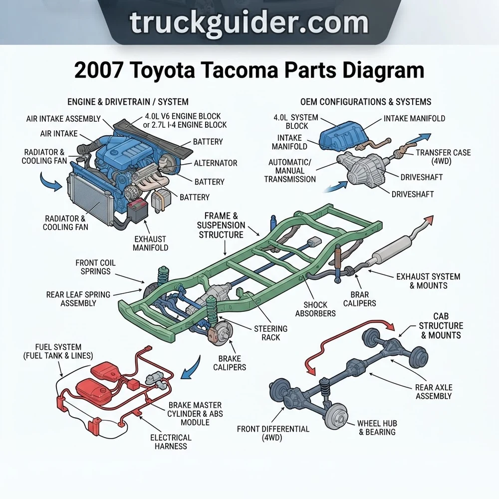
The 2007 Toyota Tacoma parts diagram illustrates exploded structural assemblies across major systems, including the 4.0L 1GR-FE V6 or 2.7L 2TR-FE powertrains, A750E transmission, and double-wishbone front suspension. It details OEM reference callouts, sub-assembly groupings, hardware specifications, and interconnecting line routings essential for accurate mechanical identification and chassis alignment.
📌 Key Takeaways
- Major powertrain layouts distinguish the 2.7L 2TR-FE DOHC I4 from the 4.0L 1GR-FE V6 configuration.
- Front suspension diagrams specify torque values: lower ball joint bolts require 37 lb-ft plus a 90-degree turn.
- Critical identification relies on 10-digit Toyota OEM base part numbers matched to your specific VIN sub-model.
- Secondary air injection system valves and intermediate steering shafts represent frequent mechanical failure points.
- DIY service is ideal for bolt-on sensors and suspension links; frame-weld or internal transmission repairs require professional technicians.
Executing accurate repairs, scheduled maintenance, or complete chassis restorations on a second-generation N200 platform requires navigating the 2007 toyota tacoma parts diagram with mechanical precision. Toyota’s engineering ecosystem relies on organized technical schematics that isolate individual sub-assemblies down to the individual flange bolt, O-ring, and structural crossmember. For shop technicians, fleet mechanics, and advanced DIYers, deciphering these exploded diagrams eliminates parts-order inaccuracies, prevents fitment failures across divergent cab configurations, and ensures assemblies are torqued and mounted to original equipment manufacturer (OEM) factory specifications. This technical guide examines the layout, interpretation, and practical troubleshooting workflows for the 2007 model year schematics.
2007 Toyota Tacoma Parts Diagram System Layout and Architecture



The blueprint architecture of the 2007 Toyota Tacoma catalog conforms to the standardized database hierarchy established within the official Toyota Electronic Parts Catalog (EPC). In this structural ecosystem, the vehicle is cataloged under the Second Generation platform (running from the 2005 through 2015 model years). The catalog divides the entire pickup into four primary operational groups: Tool/Engine/Fuel, Power Train/Chassis, Body, and Electrical. Each primary group branches into specific mechanical systems, sub-assemblies, and localized exploded illustrations.


Navigating these schematics requires an immediate operational understanding of your truck’s baseline configuration. In 2007, Toyota deployed distinct chassis codes depending on wheel-drive system, cab size, and powertrain. For example, a two-wheel-drive platform is divided between the standard 5-lug layout (chassis designation TRN220) and the PreRunner Trim (such as GRN265 or TRN265). The PreRunner retains a two-wheel-drive transmission setup but utilizes the elevated ride height, 6-lug hub configuration, subframe bracing, and suspension geometry of the four-wheel-drive (4WD) chassis (GRN245/GRN250). Selecting parts from the incorrect chassis schematic will result in acquiring incompatible control arms, brake rotors, and steering knuckles.
When referencing engine diagrams, verify whether your platform uses the 2.7L inline-4 (2TR-FE) or the Toyota 1GR-FE (4.0L V6). The 1GR-FE utilizes a dual overhead cam (DOHC) arrangement with single VVT-i (Variable Valve Timing with intelligence) on the intake cams for 2007, necessitating specific timing cover gasket arrays and distinct water pump casting callouts that do not interchange with subsequent dual-VVT-i iterations.
The system layout organizes parts into logical functional chains. Within the Toyota EPC, an assembly schematic begins with the major structural casting (such as an engine cylinder block or differential housing) and radiates outward to bearings, seals, fasteners, and bracketry. Fasteners depicted in the schematic are marked with directional arrows indicating installation angle and pass-through order. When servicing complex powertrain layouts, technicians should cross-reference this catalog with the 1GR-FE valve clearance adjustment procedure to ensure matched shims and lifter buckets are sourced according to exact mechanical tolerances.
Second-Gen Platform Architecture and EPC Groupings


The second-generation platform introduces modular chassis sections designed to absorb kinetic energy while maintaining high torsional rigidity. Within the EPC, mechanical groups are categorized under dedicated numerical sections: Section 1 covers the engine mechanical assembly, valvetrain, cooling, and intake/exhaust routing. Section 4 dictates front and rear suspension, steering linkages, propeller shafts, and axle housings. Section 5 contains hydraulic and mechanical brake linkages, anti-lock brake actuators, and pedal assemblies. Understanding this layout allows you to move directly to the target system without searching broad, vehicle-wide indexes.
Powertrain and Drivetrain Configurations: 1GR-FE vs. 2TR-FE
Powertrain selection directly dictates the front subframe crossmember shape and drivetrain schematics. The 1GR-FE 4.0L V6 is coupled to either an A750E/A750F 5-speed automatic or an RA60 6-speed manual transmission. Conversely, the 2TR-FE utilizes the A340E 4-speed automatic or the R155F 5-speed manual. Because engine mounting brackets, bellhousing patterns, and intermediate shaft lengths diverge across these pairings, catalog schematics segregate these assemblies using production identification codes stamped on the door jamb certification label.


2007 Toyota Tacoma Parts Diagram Component Breakdown by Assembly


The exploded mechanical views within the 2007 Toyota Tacoma parts catalog isolate every functional sub-assembly down to its base hardware. When ordering replacement parts or reassembling complex mechanical systems, technicians must cross-reference the exploded visual layout with precise component positions, functional roles, and trim-specific variations. The reference table below details key assemblies across the suspension, engine, drivetrain, and structural frame systems for the 2007 model year.
| Assembly Schematic | Physical Location | Key Included Components | Trim & Engine Variations |
|---|---|---|---|
| Front Suspension & Steering Diagram | Front lower chassis, steering knuckle, and engine cradle subframe | Double wishbone A-arms, coil-over shock absorber, steering knuckle, sway bar links, rack-and-pinion assembly, outer tie-rod ends | 5-Lug Base models use under-slung coil springs and integrated ball joints; 6-Lug (4WD/PreRunner) models use high-clearance forged knuckles with bolt-on lower ball joint assemblies. |
| Engine Mechanical Diagram (1GR-FE) | Engine bay forward of firewall, mounted longitudinally to front crossmember | Aluminum engine block, dual cylinder heads, single VVT-i cam sprockets, primary/secondary timing chains, hydraulic tensioners, oil pump, water pump | Specific to 4.0L V6 models. Air injection system pipe routing varies between early-run 2007 and late-run models depending on California emissions compliance. |
| Drivetrain & Axle Diagram | Undercarriage, center driveline, and rear axle housing assembly | Two-piece driveshaft, center support bearing (carrier bearing), rear leaf springs, 8.0-inch or 8.4-inch differential carrier, semi-floating axle shafts, rear drum assemblies | Manual vs. automatic driveshaft lengths vary; TRD Off-Road packages feature an 8.0-inch differential with electric locking actuator; non-locking models use the 8.4-inch (without cross-pin shim failure point) open carrier. |
| Frame & Crossmember Diagram | Full-length structural skeleton beneath body tub and bed | Boxed front frame rails, C-channel center sections, open C-channel rear rails, transmission crossmember, rear shock crossmember, spare tire hoist | Wheelbase splits dictate frame part numbers: Regular Cab (110.0 in), Access Cab / Double Cab Short Bed (127.4 in), and Double Cab Long Bed (140.6 in). |
Critical Torque Values for Diagram Hardware: Lower Control Arm Camber Alignment Cam Bolts: 100 ft-lbs (136 Nm); Front Wheel Hub/Bearing Unit-to-Knuckle Bolts: 80 ft-lbs (108 Nm); Front Brake Caliper Slide Bolts: 54 ft-lbs (73 Nm); Differential Ring Gear Mounting Bolts (1GR-FE 8.4-inch): 96 ft-lbs (130 Nm); Spark Plugs (1GR-FE): 15 ft-lbs (20 Nm).
Key Mechanical Subsystem Callouts and Reference Data
Each subsystem illustrated within the exploded catalog relies on interconnected hardware that must be replaced in tandem during mechanical overhauls. As shown in the diagram above, the Front Suspension & Steering Diagram identifies not only the primary control arms but also critical alignment hardware. The eccentric camber and caster alignment bolts (PNC 48409 and 48452) frequently seize inside the lower control arm bushings due to galvanic corrosion. When ordering replacement control arms (PNC 48068-RH and 48069-LH), technicians must order the corresponding adjusting cams, inner sleeves, and self-locking flange nuts to ensure successful alignment.
In the Engine Mechanical Diagram, pay close attention to the timing components. The primary timing chain connects the forged steel crankshaft to the intake camshaft sprockets, driven by hydraulic tensioner assembly (PNC 13540). The dual secondary chains drive the exhaust camshafts via secondary tensioners (PNC 13550 and 13560). According to OEM specs, failure to replace the O-rings behind the timing cover oil galleries (PNC 96721-24018) during a front-cover reseal can cause engine oil pressure drops and subsequent VVT-i DTC codes (such as P0011 or P0012).



How to Read a 2007 Toyota Tacoma Parts Diagram Step by Step


Accurately translating visual schematics into orderable physical components requires a systematic methodology. Dealership-level parts systems do not place full 10-digit or 12-digit part numbers directly onto exploded view schematics because an individual illustration often applies across dozens of model years, regional trims, and equipment levels. Follow these technical steps to decode the catalog without error.
- Isolate Vehicle Identification Data Using the VIN Filter: Begin by extracting the 17-digit Vehicle Identification Number (VIN) from the metal plate affixed to the lower corner of the windshield or the driver-side B-pillar certification label. Input this sequence into the Electronic Parts Catalog (EPC) search engine. The VIN filter decodes critical internal parameters including factory production date (e.g., 03/07), paint code, interior trim code, transmission type (e.g., A750E vs. RA60), and market destination (USA vs. Canada). Filtering by VIN instantly eliminates dozens of non-applicable illustrations from your search matrix.
- Locate the Relevant Major Group and Sub-Assembly Exploded View: Identify the functional mechanical domain requiring service. If diagnosing driveline vibration, navigate through “Power Train/Chassis” to “Propeller Shaft & Universal Joint.” Open the high-resolution exploded view. This visual representation maps how internal bearings, retainers, balance weights, and snap rings interface relative to one another along the rotational axis.
- Identify the Part Number Callout (PNC): Within the exploded schematic, locate the target component visually. Attached to the component is a numerical callout—typically five digits, occasionally followed by a letter or suffix (e.g., 48510 for a front shock absorber assembly, or 04465 for a front disc brake pad kit). This five-digit sequence is the Part Number Callout (PNC). It acts as an internal functional identifier across all Toyota models but is not the full, orderable OEM part number.
- Cross-Reference the PNC to the Bill of Materials Index: Select the PNC within the digital catalog interface to generate the corresponding tabular parts list. The system matches the 5-digit PNC against your truck’s specific build parameters (validated by the VIN). For example, clicking PNC 48510 on a 2007 4WD Double Cab will filter out the base 5-lug strut assemblies and display the explicit, orderable 10-digit number (such as
48510-09L40or its superceded equivalent). - Verify Quantity-Per-Assembly and Associated Hardware Callouts: Review the quantity indicator (QTY) column within the bill of materials. If servicing the rear leaf spring shackles (PNC 04483), the catalog indicates whether the callout covers one side only (QTY: 2 required per vehicle) or an entire axle kit. Note any linked standard hardware codes (e.g., starting with
90105-for standard flange bolts or90179-for prevailing-torque locknuts) shown adjacent to the primary part to ensure all one-time-use hardware is secured.
Do not attempt to order parts using only the 5-digit PNC! A PNC such as 16100 simply designates a generic “Water Pump Assembly” across the entire Toyota catalog. Ordering with a PNC alone will result in order cancellation or fulfillment of incorrect parts for an entirely different platform or model year.
Deciphering OEM Exploded Views into 10-Digit Part Numbers


A complete Toyota OEM part number consists of a 10-digit alphanumeric format (e.g., XXXXX-YYYYY), occasionally followed by a 2-digit suffix indicating color, finish, or supersession changes. The first five characters (`XXXXX`) represent the base component function, corresponding directly to the PNC identified in the schematic. The final five characters (`YYYYY`) designate the specific design execution, material variation, engine match, and production revision. When viewing electronic schematics, look for an asterisk (*) next to a part number, indicating a mid-year production split where Toyota altered the component design midway through the 2007 model run.
Troubleshooting 2007 Toyota Tacoma Schematic Mismatches and Errors


Parts ordering errors on the 2007 Tacoma almost always stem from overlooked platform nuances rather than catalog defects. Because Toyota shared high-level body pressings across radically different mechanical foundations, technicians who rely on quick visual assumptions rather than verified schematics encounter frequent component mismatches.
The most pervasive mistake occurs within the chassis and running gear schematics when differentiating between the standard 5-lug 4×2 model and the PreRunner (6-lug 4×2). The standard 5-lug model utilizes a passenger-car-style front hub assembly, compact disc rotors (276 mm), smaller brake calipers, and a spring-under-axle rear suspension design with 2.5-inch wide leaf packs. In stark contrast, the PreRunner shares the heavy-duty 4WD platform architecture: a 6-lug hub configuration, massive 319 mm front ventilated rotors, four-piston fixed calipers, a front-mounted steering rack, and a taller spring-over-axle rear layout with distinct shock absorber valving. Sourcing front suspension or brake parts under the generic “Tacoma 2WD” heading without verifying the 5-lug versus 6-lug schematic selection results in complete physical incompatibility.


Another major source of mismatch lies within the Exhaust & Emissions Diagram. 2007 model year Tacomas were produced under two distinct emissions footprints: Federal (EPA) standards and California Air Resources Board (CARB) emissions standards. The exhaust manifold and catalytic converter schematic reflects critical differences:
- Federal Emissions: Features standard upstream oxygen sensors and primary manifold catalytic converters with secondary downstream monitors.
- California/CARB Emissions: Features wideband Air/Fuel Ratio (A/F) sensors (PNC 89467) upstream, structurally reinforced catalytic converters, and tightly calibrated secondary heated oxygen sensors (PNC 89465).
Installing a Federal sensor or converter onto a California-spec truck will instantly trigger persistent Malfunction Indicator Lamp (MIL) codes, specifically P0420/P0430 (Catalyst System Efficiency Below Threshold) or A/F heater circuit fault codes. Technicians must check the Vehicle Emission Control Information (VECI) label under the hood before consulting exhaust blueprints. For additional electrical routing assistance, refer to the 2007 Toyota Tacoma wiring schematic to confirm sensor pinouts and harness continuity.
Finally, wheelbase and cab-length errors occur frequently in the Drivetrain & Axle Diagram. The 2007 Tacoma was sold in three cab configurations: Regular Cab, Access Cab (extended), and Double Cab (crew cab), paired with either a 5-foot short bed or a 6-foot long bed. This variance resulted in multiple distinct rear driveshaft assemblies. Ordering a replacement center support bearing or rear propeller shaft assembly without matching the exact cab-and-bed length configuration will result in a driveline that is structurally too long or too short, placing excessive load on the transfer case output shaft or transmission tailhousing.
Generational Overview: Comparing 2007 Tacoma Schematics Across Eras
To accurately understand the architectural placement of the 2007 model year, technicians must contrast its schematics with preceding and subsequent iterations. The table below outlines structural, mechanical, and schematic differences across four distinct eras of Toyota Tacoma production.
| Chassis Era | Bed & Frame Structure | Front Suspension Architecture | Drivetrain & Powertrain Details |
|---|---|---|---|
| 1st Gen Tacoma Parts Diagram (1995–2004) | Fully welded traditional steel inner and outer bed; narrow fully-boxed/open-channel hybrid steel frame. | Double wishbone with lower ball joints mounted in tension (prone to separation under extreme load wear). | 5VZ-FE (3.4L V6) or 3RZ-FE (2.7L I4); mechanical throttle cables on early models; smaller 7.5″ front / 8.0″ rear differentials. |
| Early 2nd Gen (2005–2011, includes 2007) | Introduction of sheet-molded composite (SMC) inner bed structure with steel exterior side skins; boxed front frame rails with open-channel mid/rear sections. | Redesigned double wishbone with lower ball joints mounted in compression beneath the knuckle (eliminates separation failures). | 1GR-FE (4.0L V6 single VVT-i) or 2TR-FE (2.7L I4); drive-by-wire electronic throttle; standard 8.0″ / 8.4″ rear differential configurations. |
| 2012–2015 Facelift Tacoma Parts Diagram | SMC composite inner bed; frame structural architecture largely identical to 2007 with updated front bumper mounting horns and radiator supports. | Mechanically identical geometry to 2007; minor sway bar diameter revisions and revised ABS wheel-speed sensor mounting clips. | Secondary air injection systems made standard across all 1GR-FE engines, introducing vacuum switching valves and air injection pumps into the schematic. |
| 3rd Gen Tacoma Parts Diagram (2016–2023) | Updated ultra-high-strength steel stamped frame components; enhanced composite inner bed with redesigned tailgate damper linkages. | Revised geometry with taller shock towers, altered control arm bushing durometers, and integrated electronic steering rack variations. | 2GR-FKS (3.5L V6 with Atkinson cycle and D-4S port/direct injection); 6-speed automatic (AC60E/F) transmissions replace the A750 series. |
Evolution from Steel Beds to Composite Bed Architectures
The transition from the 1st Gen to the 2007 2nd Gen platform marked an architectural shift in structural materials. As detailed in the comparison schematic, the 2007 model abandoned the rust-prone steel inner bed floor and wheel wells of the 1995–2004 trucks in favor of a Sheet-Molded Composite (SMC) deck. In the 2007 parts catalog, you will not find weld-in floor repair panels or steel wheelhouse tubs. Instead, the catalog illustrates a single, high-durability composite tub (PNC 65100B) fastened directly to the frame crossmembers via heavy-duty Torx T55 bed bolts. When servicing or lifting the body, technicians must refer to the specialized mounting bushing and bolt sets detailed in the body-mounting schematic.
2007 Toyota Tacoma Parts Diagram Frequently Asked Questions
Where can I find the paint and trim codes to match parts in my 2007 Tacoma diagram?
Paint and interior trim codes are stamped directly on the Vehicle Certification Label located on the driver-side door jamb. Look for the abbreviation “C/TR” at the bottom of the placard. The first three characters indicate the exterior paint code (for example, 1D6 for Silver Streak Mica or 202 for Black). The second three characters designate the interior trim code and seat fabric material (e.g., FJ13 for graphite fabric). Inputting these alphanumeric codes into the parts catalog ensures color-matched interior panels, mirror caps, and exterior painted body mouldings.
Why does my 2007 Tacoma parts diagram show two different oil filter locations?
The oil filter layout depends entirely on engine configuration. On the 1GR-FE 4.0L V6, the parts diagram illustrates an inverted, spin-on oil filter mounted on top of the engine near the front driver-side valve cover, surrounded by a specialized cast-aluminum drain catch basin. On the 2TR-FE 2.7L 4-cylinder engine, the diagram shows the spin-on oil filter mounted under the vehicle, on the lower driver-side section of the engine block beneath the intake manifold runners. Verify engine sizing before referencing lubrication schematics.
Are 4WD and PreRunner front suspension diagrams completely identical for 2007?


Yes, the front suspension mechanical diagrams for the 2007 PreRunner (4×2 6-lug) and standard 4WD (4×4 6-lug) models share identical geometries, control arms, steering knuckles, coil springs, and stabilizer bars. The primary mechanical divergence appears in the front wheel hub schematic: 4WD models route a splined CV axle shaft through the center of the bearing assembly, whereas PreRunner models use a sealed spindle cap or dummy stub shaft to support the unpowered front bearing unit without a front differential assembly. For four-wheel-drive maintenance, consult the second-generation Tacoma transfer case overhaul guide for adjacent driveline parts.
How do I identify whether my 2007 Tacoma has an 8.0-inch or 8.4-inch rear differential in the parts catalog?
The easiest method is examining the locking differential configuration in the EPC. Tacomas equipped with the TRD Off-Road package feature a factory electronic locking rear differential; this unit uses an 8.0-inch ring gear with an external electric actuator motor (PNC 41450) clearly visible on the differential housing schematic. Non-TRD Off-Road models (including TRD Sport, PreRunner base, and standard 4x4s without an e-locker) utilize what Toyota designates as an “8-inch nominal” but is known across the industry as the 8.4-inch differential. This carrier features a unified bearing cap girdle structure and lacks the side-mounted actuator found on the locked version.
What does the abbreviation “W/O” or “W/” mean on Toyota schematic callouts?
In all Toyota Electronic Parts Catalogs and schematics, “W/” translates to “With” and “W/O” translates to “Without.” These abbreviations govern conditional hardware equipment lines. For instance, a leaf spring schematic entry reading “W/ TOW PACKAGE” indicates that the spring pack includes an auxiliary overload leaf and matched U-bolts. An entry marked “W/O ABS” dictates wheel hub or master cylinder callouts for platforms that omit anti-lock brake wiring harnesses and tone rings.
Step-by-Step Guide to Understanding the 2007 Toyota Tacoma Parts Diagram
Identify – Determine your Tacoma’s cab configuration, drivetrain (2WD vs 4WD), and engine code (2TR-FE or 1GR-FE) via the VIN plate.
Locate – Find the specific subsystem diagram corresponding to the mechanical assembly needing maintenance or repair.
Reference – Match the numerical part callout on the exploded schematic with the master OEM part number list.
Connect/Route – Follow the indicated assembly order, verifying bolt thread sizes, torque values, and hose or wiring harness paths.
Verify – Cross-check mating surface clearances, ensure alignment dowels seat properly, and verify all structural fasteners meet OEM torque specs.
Troubleshoot – Consult the layout connectivity path if mechanical interference, fluid leaks, or diagnostic trouble codes persist after reassembly.