2008 GMC Sierra Fuse Box Diagram: 2026 Repair Guide

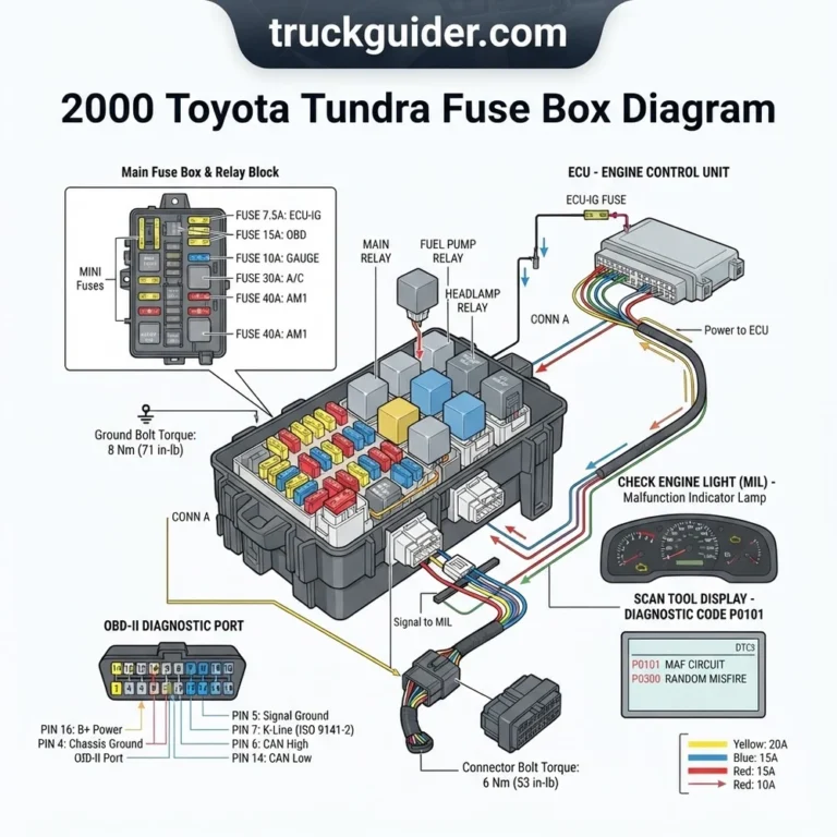
The 2008 GMC Sierra underhood fuse block sits on the driver-side engine compartment next to the battery, secured by a plastic shroud. The interior instrument panel fuse box is located on the driver-side dashboard edge behind the access cover. Key circuits include Fuse 56 (ECM/ECU), Fuse 40 (Fuel Pump), and Fuse 20 (OBD-II port).
📌 Key Takeaways
- Underhood Fuse 56 (15A) powers the ECU/ECM, while interior Fuse 20 (15A) supplies the DLC/OBD-II port and cigarette lighter.
- Terminal lugs and battery connections require a torque spec of 9 lb-ft (12 Nm) to prevent voltage drops across the junction block.
- Corrosion or loose pins beneath the Underhood Electrical Center (UEC) cause intermittent starting failure and false instrument cluster warnings.
- A blown OBD-II fuse prevents handheld scanners from linking when troubleshooting an illuminated check engine light or pulling a diagnostic code.
- Simple mini-fuse and micro-relay replacements are DIY-friendly, but damaged internal fuse block busbars require complete modular unit replacement.
The electrical infrastructure of the 2008 GMC Sierra (GMT900 platform, covering 1500, 2500HD, and 3500HD variants) relies on a centralized power distribution architecture. Navigating this network requires an accurate 2008 gmc sierra fuse box diagram to trace current from the primary B+ battery feed through high-amp J-Case links, blade mini-fuses, and solid-state relays down to sensitive control modules. Whether troubleshooting an unpowered Engine Control Unit (ECU), chasing down an intermittent check engine light, or restoring serial data transmission across the Controller Area Network (CAN-bus), identifying exact fuse locations and pinouts is the fundamental starting point for automotive diagnostics.
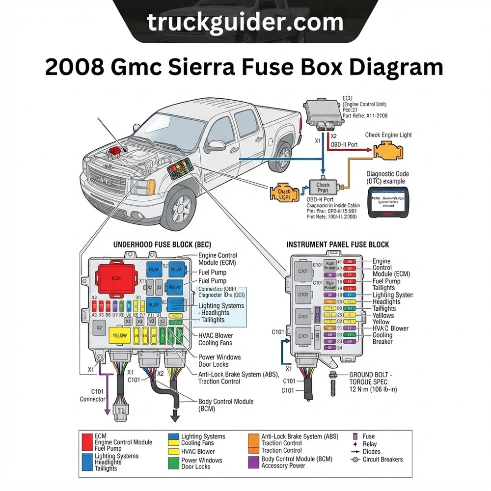
2008 GMC Sierra Fuse Box Diagram and Panel Locations


The 2008 GMC Sierra distributes electrical loads across three distinct junction blocks: the Underhood Electrical Center (UEC), the Instrument Panel (IP) Fuse Block, and an auxiliary high-current Battery Distribution Block mounted above the primary battery tray. Understanding this physical layout prevents misdiagnosis caused by chasing phantom faults when dealing with split-circuit failure modes.


The Underhood Electrical Center (UEC) serves as the primary distribution hub for high-amperage powertrain, lighting, and chassis operations. Positioned on the driver-side inner fender apron directly aft of the windshield washer fluid reservoir and forward of the brake master cylinder, this block houses both mini blade fuses (ATM style) and high-current J-Case fuses. Accessing the panel requires releasing two locking retaining tabs on the outboard plastic cowl cover and lifting vertically. On the underside of this lid, GM provides an embossed fuse chart showing exact component numbering and current ratings.
Inside the lid of the underhood electrical center, GM integrates a white nylon fuse puller tool alongside four spare fuse slots (10A, 15A, 20A, and 30A). If this puller is missing, utilize narrow plastic-jawed extraction pliers to avoid shorting adjacent hot terminals to ground during live-circuit testing.
The interior Instrument Panel Fuse Block resides on the driver-side dashboard end-cap. It is accessible only when the driver-side door is fully open. Mechanics must insert a non-marring nylon pry tool into the designated trim notch to unsnap the textured access door from the dashboard subframe. This panel acts as the terminal distribution center for the Body Control Module (BCM), passenger compartment accessories, interior lighting, and the Diagnostic Link Connector (DLC). For complete chassis ground mapping, consult our detailed GMT900 chassis ground distribution guide to prevent ground loop interference when installing aftermarket accessories.
The third panel is the Battery Distribution Center, a molded fusible link block positioned directly adjacent to or atop the starting battery. This bracket contains the main Mega Fuse links protecting the high-output alternator charging circuit and the primary feed cable running to the starter solenoid. If your Sierra suffers from an absolute zero-voltage state across the cabin and ignition switch, inspecting this high-amperage block is the required first action.
Disconnect the negative battery terminal before unbolting any J-Case fuses or the Mega Fuse links on the battery distribution block. The main battery feeder lug carries unprotected positive current capable of welding hand tools directly to the chassis frame rail, resulting in rapid thermal battery runaway.
Underhood 2008 GMC Sierra Fuse Box Diagram: Engine Bay Circuits


The Underhood Electrical Center operates on a direct 12-volt battery bus line and an ignition-switched Run/Crank bus driven through the powertrain relay matrix. Fuses in this panel protect fuel delivery, throttle actuation, ignition coils, and cooling fan operation. Below is the technical specification table for the primary circuits within the underhood block.


| Position / ID | Fuse Type | Rating | Protected Circuit / Wire Feed |
|---|---|---|---|
| FUSE 1 (ECM) | Mini Blade | 15A | Engine Control Module (ECU) B+ Battery Memory & Logic |
| FUSE 2 (ECM / TCM) | Mini Blade | 15A | Transmission Control Module & Engine Run/Crank Feed |
| FUSE 5 (INJ A) | Mini Blade | 15A | Odd Fuel Injectors (Cyl 1, 3, 5, 7) – Pink Wire |
| FUSE 9 (INJ B) | Mini Blade | 15A | Even Fuel Injectors (Cyl 2, 4, 6, 8) – Pink/Black Wire |
| FUSE 13 (IGN) | Mini Blade | 15A | Ignition Coils & Engine Sensors Reference Power |
| FUSE 15 (TRLR B/U) | Mini Blade | 10A | Trailer Backup Lamps / 7-Pin Connector Center Pin |
| FUSE 17 (ABS 2) | J-Case | 40A | Antilock Brake System Pump Motor |
| FUSE 20 (F/PMP) | Mini Blade | 20A | In-Tank Fuel Pump Motor & Sending Unit Assembly |
| FUSE 23 (STRTR) | J-Case | 30A | Starter Solenoid Relay Contact Feed – Purple Wire |
| FUSE 28 (FAN 1) | J-Case | 40A | Primary Electric Radiator Cooling Fan Assembly |
| FUSE 34 (FAN 2) | J-Case | 40A | Secondary Electric Radiator Cooling Fan Assembly |
| FUSE 56 (O2 B1S1) | Mini Blade | 15A | Upstream / Downstream Heated Oxygen Sensor Heaters |
| FUSE 63 (STUD 1) | J-Case | 40A | Auxiliary Battery Feed / Heavy Duty Trailer 12V B+ |
| FUSE 67 (STUD 2) | J-Case | 30A | Trailer Brake Control Module Harness Harness Terminal |
| RELAY 43 (PWR/TRN) | Micro Relay | 35A | Powertrain Main System Relay (ECU Actuated Ground) |
| RELAY 55 (STRTR) | Micro Relay | 35A | Starter Motor Solenoid Control Relay |
The underhood center isolates the high-demand radiator cooling fans. Because the Gen IV Vortec engine platform relies on dynamic pulse-width modulation and staggered dual-fan activation to manage operating temperature, a blown 40A J-Case link at position 28 or 34 disrupts balanced coolant flow through the crossflow radiator core. If one cooling fan circuit blows while towing, the engine bay temperatures surge rapidly, directly compromising fluid viscosity, transmission temperature, and engine oil pressure.
Mechanics tracing intermittent crank-no-start conditions must test pin 30 and pin 87 across Micro Relay 43. When the ignition is rolled forward to “Run”, the ECU commands this relay closed by pulling pin 85 to ground. If the internal relay copper coil degrades (acceptable resistance is 75 to 90 ohms across pins 85 and 86), the contacts will fail to latch, denying unswitched battery current to the fuel injectors and spark packs.
Interior 2008 GMC Sierra Fuse Box Diagram and Cabin Layout


The interior Instrument Panel Fuse Block directly safeguards the complex passenger compartment network. It handles the interface between human inputs (steering column controls, power windows, seat modules) and the onboard network architecture governed by the Body Control Module. When cabin electronics behave erratically, consulting the cabin 2008 gmc sierra fuse box diagram provides the exact route to isolate the source.


| Cavity / Label | Fuse Type | Rating | Circuit Destination / Switched State |
|---|---|---|---|
| FUSE 1 (AIRBAG) | Mini Blade | 15A | Sensing and Diagnostic Module (SDM) / Hot in Run |
| FUSE 2 (CLUSTER) | Mini Blade | 10A | Instrument Panel Cluster (IPC) Power / Hot in Run |
| FUSE 12 (RADIO) | Mini Blade | 15A | Audio Head Unit / Rear Entertainment Module (B+) |
| FUSE 16 (DLC / AUX) | Mini Blade | 20A | Data Link Connector (Pin 16) & Cigarette Lighter 1 |
| FUSE 17 (AUX POWER 2) | Mini Blade | 20A | Center Console 12V Auxiliary Receptacle (Constant B+) |
| FUSE 18 (BCM 1) | Mini Blade | 15A | Body Control Module Logic Power (Unswitched) |
| FUSE 19 (BCM 2) | Mini Blade | 15A | Interior Lighting & Dimmer Circuit Matrix |
| FUSE 22 (PEDALS) | Mini Blade | 15A | Adjustable Accelerator and Brake Pedal Motor |
| CB 1 (DOOR LOCKS) | Auto-Reset CB | 25A | Power Door Lock Actuator Solenoids |
| CB 2 (SEATS) | Auto-Reset CB | 30A | Six-Way / Eight-Way Power Driver Seat Adjusters |
The interior block utilizes thermal auto-reset circuit breakers for the door locks and power seats. These bi-metallic switches expand and break the circuit during excessive mechanical load (such as a seized driver-side power lock actuator). Once the current drops and the metal element cools, the breaker resets automatically. If power cuts out repeatedly while adjusting the seats, the culprit is mechanical friction or a failing motor dragging high amperage, rather than a permanently blown fuse.
A vital detail for technicians is the shared architecture between Fuse 16, the accessory 12V cigarette lighter sockets, and the onboard diagnostics port. The SAE J1962 OBD-II DLC connector relies exclusively on the positive battery feed supplied through Cavity 16 to power diagnostic scan tools. When performing BCM updates or key-relearning steps, referenced in our guide on Silverado and Sierra BCM replacement procedures, verifying clean, noise-free voltage at this junction is an absolute prerequisite.
Factory pinout specifications dictate that Pin 16 of the interior Data Link Connector must register a minimum of 11.8 Volts DC directly to chassis ground (Pin 4) and signal ground (Pin 5) with the ignition switch turned off. Any drop below this voltage points directly to terminal corrosion at Fuse 16.
Correlating Blown Fuses to Diagnostic Trouble Codes and Check Engine Light Faults


A blown fuse rarely occurs in isolation. In the 2008 GMC Sierra, a short circuit immediately impacts the powertrain management system, causing the instrument cluster to illuminate the check engine light and store one or more Diagnostic Trouble Codes (DTCs). Technicians frequently spend hours chasing complex mechanical failures—ranging from internal timing chain stretch to oil control ring failure—when the true issue is an unpowered sensor branch.
- No Communication with Diagnostic Scanner (Blank OBD-II Tool): When your scan tool fails to boot or cannot initialize a handshake with the powertrain network, do not condemn the ECU. In over 80% of cases on GMT900 trucks, a blown 20A Fuse 16 in the interior IP fuse block has severed battery positive current to Pin 16 of the DLC. Foreign metal debris trapped inside the center console cigarette lighter socket is the primary cause of this failure.
- Codes P0135, P0141, P0155, P0161 (Oxygen Sensor Heater Circuits): These diagnostic codes indicate internal heater failure across Banks 1 and 2. While an amateur diagnosis points toward replacing all four oxygen sensors, this simultaneously occurring pattern almost always stems from a blown 15A Underhood Fuse 56. The heater wire harnesses pass close to the front driveshaft and exhaust manifolds, where direct friction can abrade the harness jacket and cause a dead short to the chassis.
- Codes P0011, P0016 (Camshaft/Crankshaft Correlation Errors): Mechanics frequently jump to the conclusion that a stretched timing chain or failed variable valve timing (VVT) phaser is the primary fault. However, if the 15A IGN Fuse 13 in the engine bay blows or suffers an extreme voltage drop, the VVT oil control solenoid and the camshaft position sensor lose stable bias voltage. This loss shifts the calculated position table out of boundary limits, triggering false engine timing codes.
- Codes P0521, P0522 (Oil Pressure Sensor Circuit Range/Performance): The 2008 5.3L and 6.0L Vortec engines route reference voltage to the rear-mounted engine oil pressure sending unit through the secondary regulated ignition circuit. If terminal fret occurs at the underhood center connector blocks, the oil pressure gauge drops instantly to 0 PSI, accompanied by an aggressive warning chime and a “Low Oil Pressure – Turn Off Engine” notification on the Driver Information Center (DIC).
- Trailer Brake System Failure DIC Message: When towing, the internal dashboard display may read “Service Trailer Brake System.” Inspect Underhood J-Case Fuses 63 (40A) and 67 (30A). If trailer lighting wires short inside an aftermarket 7-pin trailer connector assembly, these high-amp feeds pop instantly, removing emergency electric brake controller power to the trailer axle assemblies.
For deep-dive wire routing between the sensors and the ECU, cross-reference our master Gen IV Vortec engine wiring schematics to verify splice pack physical locations within the main engine harness loom.


Diagnostic Procedure for 2008 GMC Sierra Fuse Box Circuits
Testing and repairing electrical faults in modern trucks requires an analytical workflow. Pulling every fuse randomly resets the ECU adaptive keep-alive memory, clearing freeze-frame diagnostics and complicating troubleshooting. Follow this systematic process using a Digital Multimeter (DMM) and a 12V automotive test light.
- Isolate the Power Condition: Determine whether the faulty circuit is designated as Unswitched Battery Power (Hot at all times) or Switched Ignition Power (Hot in Run/Crank). Refer to the 2008 gmc sierra fuse box diagram tables above. If the circuit operates on switched logic, rotate the truck ignition key to the “Run” position with the engine off.
- Execute Voltage-Drop Testing via Test Points: Do not extract the mini blade fuses. Connect the alligator ground clip of your high-impedance 12V test light to a solid chassis ground point (such as the bare steel steering column mount or engine block ground lug). Lightly touch the probe tip to both tiny exposed metal test pads on the top face of the ATM fuse.
- Both pads light up: The fuse is intact and carrying source voltage down the circuit line.
- One pad lights up, one is dead: The fuse element is open (blown) and must be extracted for replacement.
- Neither pad lights up: The circuit is unpowered upstream; inspect the feeding powertrain relay or the main ignition switch bus.
- Measure Precise Operating Circuit Voltage: Set your Digital Multimeter to DC Volts (20V scale). Place the red positive probe on the active fuse test pad and the black negative lead to ground. The measurement must read within 0.2 Volts of total battery resting voltage (typically 12.4V to 12.7V DC). Any reading showing a significant drop (e.g., 9.2V) highlights resistive corrosion within the underhood block bus bars or terminal clips.
- Conduct Load Testing on Micro Relays: To verify an underhood relay (such as the Run/Crank or Starter Relay), extract the component using your fingers. Using your multimeter in resistance mode (Ohms), measure across pins 85 and 86. Resistance must register between 70 and 90 ohms. Then, apply 12 volts external DC power across pins 85 and 86 using a fused jumper; you should hear a crisp mechanical click. Measure continuity between load pins 30 and 87; resistance across closed contacts must read less than 0.5 ohms.
- Inspect Battery Distribution Mega Fuse Torque: When unbolting the heavy-gauge 125A or 175A Mega Fuse bars on the battery-top distribution block, you must retorque the fasteners to specification upon reinstallation. Loose connections induce thermal build-up that melts the plastic casing and mimics alternator failure.
According to OEM specifications, the M8 terminal nuts securing the high-amperage cables to the battery distribution Mega Fuse require a strict torque spec of 9 Nm (80 lb-in). The smaller M6 studs for auxiliary power feeds require a torque spec of 5 Nm (44 lb-in). Never over-tighten these studs, as this will fracture the molded battery casing.
Frequently Asked Questions: 2008 GMC Sierra Fuse Box Diagnostics
Why does my OBD-II port have no power when trying to read a diagnostic code?


On a 2008 GMC Sierra, the 16-pin Diagnostic Link Connector (DLC) draws its constant 12-volt operating power from the cabin Instrument Panel Fuse Block via Fuse 16 (labeled DLC / AUX, rated at 20A). This specific circuit is wired directly in parallel with the interior 12-volt cigarette lighter socket. If a phone charger, coin, or foreign metal object drops inside the front dash lighter receptacle, it causes a short circuit that immediately blows Fuse 16. Replacing the 20-amp mini-blade fuse and cleaning out the accessory socket will instantly restore pin 16 power to your scan tool.
Which fuse controls the fuel pump relay and fuel pressure on the 2008 Sierra?
The electric fuel pump motor located inside the fuel tank is protected by Fuse 20 (F/PMP), a 20-amp mini blade fuse housed in the Underhood Electrical Center. Switched activation is managed by Relay 56, positioned right beside the fuse. If you experience an extended crank or zero fuel rail pressure, test both terminals of Fuse 20 with the ignition cycled to “Run.” If the fuse is completely functional, verify that the fuel pump relay clicks audibly during the two-second priming cycle when the key is rolled forward from the “Off” position.
How do I identify a blown J-Case fuse compared to a standard mini blade fuse?
Standard mini blade fuses (ATM style) feature a semi-translucent plastic casing that lets you view the curved zinc element directly from the side. In contrast, J-Case fuses are square cartridge-style fuses designed for higher current loads (typically 30A to 60A). They feature a clear top-inspection window. Look directly down through this clear window under bright light: an intact J-Case fuse displays a continuous, heavy dual-arch terminal link. If the circuit has experienced an overcurrent event, this link will be melted, severed, and typically accompanied by dark carbon flash residue on the inside of the clear window.
Can a blown fuse cause the transmission to become stuck in limp mode?


Yes. The Transmission Control Module (TCM) and the internal electronic transmission solenoids inside the 4L60-E or 6L80-E transmission draw their primary operational power from Underhood Fuse 2 (15A, labeled ECM / TCM). If this fuse blows due to a pinch in the harness running near the bellhousing, the transmission solenoids lose holding voltage. This forces the transmission into mechanical third-gear failsafe (limp mode) to prevent catastrophic planetary gear damage. This failure condition triggers an immediate check engine light alongside stored diagnostic codes U0101 (Lost Communication with TCM) and P0700.
What causes the Mega Fuse on the battery distribution block to fail repeatedly?
The 175-amp Mega Fuse on the battery bracket blows primarily due to a direct short circuit along the heavy-gauge starter battery cable. The positive starter motor lead routes tightly between the engine block, motor mount, and frame rail. Over years of thermal cycling and engine torquing, the corrugated protective loom rots, allowing the heavy cable to rub directly against the sharp steel edge of the motor mount bracket. When the starter is energized, current bypasses the starter field windings and shorts directly to ground, rupturing the 175-amp link instantly. Inspect the entire run of positive battery cable down to the starter solenoid terminal before bolting in a replacement Mega Fuse.
Step-by-Step Guide to Understanding the 2008 Gmc Sierra Fuse Box Diagram
Identify – Switch ignition off and identify the symptomatic circuit using owner schematics or fuse labeling.
Locate – Locate the corresponding fuse box under the hood or along the driver-side instrument panel edge.
Reference – Reference the legend embossed on the cover to verify the correct fuse slot number and rating.
Inspect – Extract the fuse using a puller and inspect the internal metal filament for melting or separation.
Verify – Insert an exact-match replacement fuse, restore battery power, and verify proper accessory operation and supply voltage.
Troubleshoot – Connect a diagnostic scanner to check for an active diagnostic code or check engine light if issues persist.