2008 Toyota Tacoma Parts Diagram: 2026 Component Guide

The 2008 Toyota Tacoma parts diagram maps assembly groups across the 2.7L 2TR-FE and 4.0L 1GR-FE powertrains, A750E/F transmissions, and ladder chassis structure. Sub-diagrams isolate callout numbers to OEM part numbers, specifying torque thresholds such as 85 lb-ft for front hub bolts and 37 lb-ft for secondary air injection valves.
📌 Key Takeaways
- Identifies powertrain differences between the 2.7L 2TR-FE I4 and 4.0L 1GR-FE V6 engine layout schematics.
- VIN verification is required to identify sub-model configuration splits between PreRunner, 4WD, and Base trims.
- Crucial safety torque specification: Front lower ball joint mounting bolts require exactly 59 lb-ft with thread locker.
- Primary wear points include the secondary air injection check valve system and rear leaf spring hanger perches.
- DIY-friendly for bolt-on suspension and brake overhauls, but professional alignment or frame rust remediation is advised.
Navigating the mechanical architecture of the second-generation Toyota Tacoma requires an exact understanding of its engineering diagrams. Whether you are performing a complete frame-off restoration, overhauling a 1GR-FE 4.0L V6 or 2TR-FE 2.7L I4 engine, or diagnosing driveline vibration, an authentic 2008 Toyota Tacoma parts diagram serves as the definitive reference blueprint. Factory exploded views eliminate the guesswork of fastener torque values, assembly sequence, part supersede pathways, and chassis variation. This guide deconstructs the primary mechanical assemblies, chassis schematics, and catalog classification systems utilized by factory technicians and professional mechanics to keep the 2008 model operating to OEM specifications.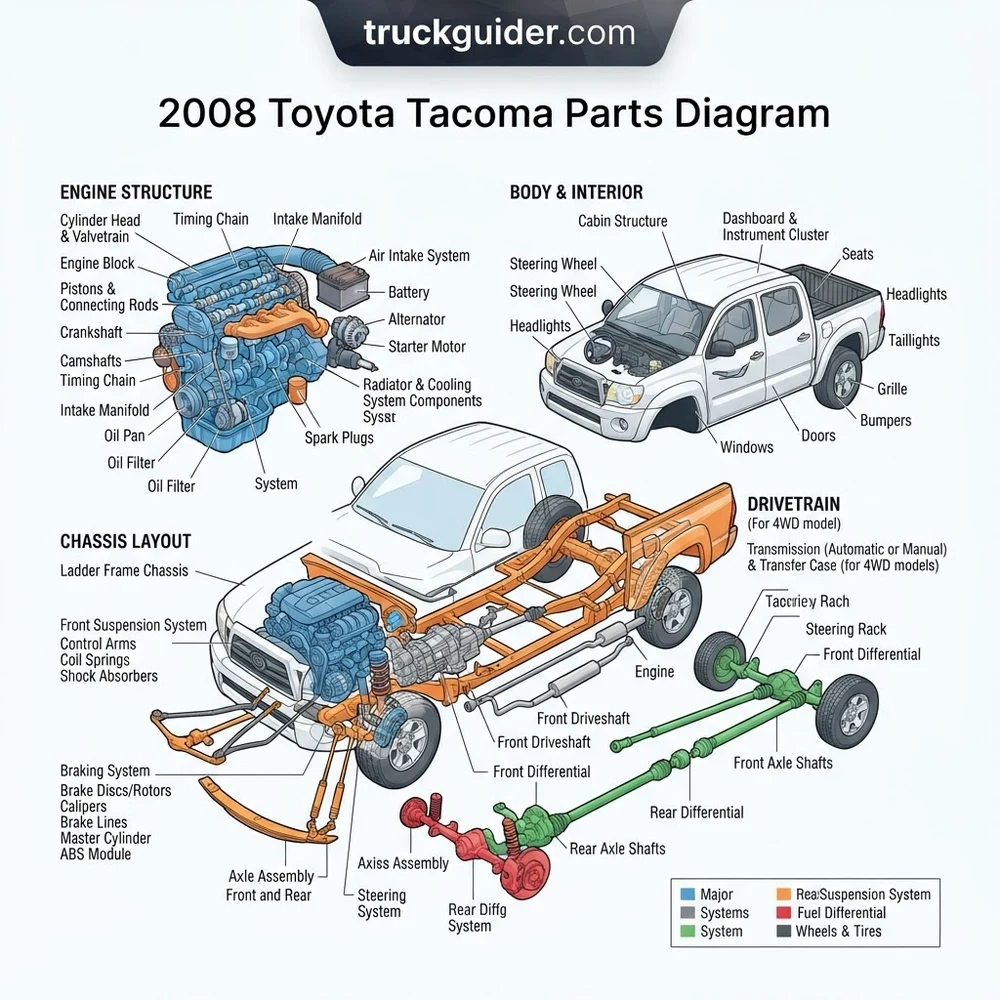
2008 Toyota Tacoma Parts Diagram: Core System Layout




The powertrain, suspension, and chassis of the 2008 Tacoma rely on interconnected sub-assemblies cataloged under distinct mechanical groups within the factory documentation. When viewing a master assembly schematic, components are grouped by structural function and sub-system location. Understanding these core groupings enables you to isolate sub-components and identify exact fastener locations, sealing interfaces, and service limits.


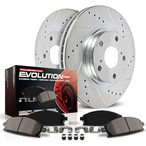
Factory assembly diagrams specify torque tolerances: Front lower control arm cam bolts require 100 ft-lbs (135 Nm); spindle-to-lower ball joint bolts require 118 ft-lbs (160 Nm); rear U-bolt nuts require 37 ft-lbs (50 Nm) in a progressive cross-pattern sequence.
Powertrain and Engine Assembly Layout


The 2008 Toyota Tacoma utilizes either the 2.7L inline-4 (2TR-FE) or the 4.0L V6 (1GR-FE). The engine schematic isolates the cylinder block, cylinder head, valvetrain, timing chain cover, and intake manifold. On the 1GR-FE diagram, special focus is placed on the front timing chain assembly (Catalog Group 13-02). This layout reveals the primary timing chain, dual secondary chains for the Variable Valve Timing with intelligence (VVT-i) sprockets, hydraulic tensioners, and tensioner slipper shoes. Mechanics addressing oil leaks will reference the timing chain cover exploded view, which details the 24 perimeter bolts across three distinct thread lengths (M6x1.0, M8x1.25, and M10x1.25), along with the crankshaft front oil seal (OEM Part Name Code 11302).
Front Suspension and Steering Linkage Diagram
The front suspension schematic depicts a high-mount double-wishbone design on 6-lug models (PreRunner and 4WD) and a traditional independent SLA configuration on base 5-lug models. The steering assembly diagram integrates the rack-and-pinion gear casing, intermediate steering shafts, outer tie-rod ends, and power steering pump hydraulic circuit. The schematic separates the lower control arm (LCA) from the crossmember using eccentric alignment cam sleeves and adjusting bolts. Technicians referencing the steering linkage layout must note the secondary collapsible slip joint in the steering column—a mandatory safety structure designed to deform under collision loads.
Drivetrain and Transfer Case Configuration
Drivetrain schematics for 4WD variants display the VF2A or VF2BM transfer case, split into front/rear case halves, planetary reduction gears, and the electric 4WD actuator motor. The front differential assembly (Group 41-01) includes the Automatic Disconnecting Differential (A.D.D.) actuator tube, which disengages the passenger-side intermediate axle shaft to eliminate front driveline drag in 2WD mode. Driveshaft layouts illustrate the two-piece rear propeller shaft with a center support bearing (carrier bearing) and double-cardan or standard universal joints. Cross-referencing the Tacoma drivetrain torque and clearance specifications ensures proper backlash and bearing pre-load alignment during reassembly.
Rear Axle and Leaf Spring Structural Assembly


The rear axle diagram highlights the robust 8.0-inch or 8.4-inch (non-locking) and 8.0-inch e-locker Toyota rear differential housings. Suspended by multi-leaf spring packs, the diagram clarifies the offset pin placement, spring shackles, rubber bump stops, and staggered rear shock absorber geometry. This staggered shock layout—one shock mounted forward of the axle tube and one rearward—controls axle wrap under torque load, making orientation clarity in the parts schematic critical during replacement.



| System / Diagram Group | Primary Components Shown | Key Factory Torque Specs | Catalog Identification Focus |
|---|---|---|---|
| Engine Assembly (1GR-FE 4.0L) | Cylinder head, timing chain, sprockets, water pump, oil pan | Timing cover M8: 17 ft-lbs; Cam gears: 74 ft-lbs; Oil drain plug: 30 ft-lbs | PNC 11310 (Timing Cover), PNC 13506 (Timing Chain) |
| Front Suspension (6-Lug) | Upper/lower control arms, steering knuckle, coilover assembly | LCA Cam Bolts: 100 ft-lbs; Upper Ball Joint: 81 ft-lbs; Hub Bolts: 80 ft-lbs | PNC 48068 (Right LCA), PNC 48069 (Left LCA) |
| Steering Gear & Linkage | Rack & pinion, inner/outer tie rods, steering intermediate shaft | Tie-rod end locknut: 53 ft-lbs; Rack mounting bolts: 141 ft-lbs | PNC 44200 (Steering Gear Assy), PNC 45046 (Outer Tie Rod) |
| Transfer Case (VF2A) | Planetary gear set, shift rails, electric A.D.D. motor, seals | Companion flange nut: 87 ft-lbs; Drain/fill plugs: 27 ft-lbs | PNC 36110 (Case Sub-Assy), PNC 36410 (T-Case Actuator) |
| Rear Axle & Suspension | Differential carrier, axle shafts, leaf springs, U-bolts, shackles | Leaf spring eye bolt: 89 ft-lbs; U-bolt nuts: 37 ft-lbs; Shackle bolt: 67 ft-lbs | PNC 48210 (Leaf Spring Assy), PNC 42110 (Axle Housing) |
Tacoma Drivetrain and Frame Schematics by Trim Configuration


The second-generation Toyota Tacoma (2005–2015) platform features sharp structural divergence depending on chassis configuration, cab dimension, wheel hub setup, and drive configuration. Ordering or rebuilding parts without verifying the specific configuration schematic frequently leads to incompatible components.
Do not interchange suspension components between 5-lug and 6-lug frames. Spindles, control arms, ball joints, and steering geometry are entirely non-interchangeable between these chassis designs.
5-Lug Base Platform vs. 6-Lug Chassis Architecture
The 2008 Tacoma line is bifurcated into two foundational platform formats:
- 5-Lug Platform: Utilized exclusively on Regular and Access Cab base utility models and the specialized X-Runner trim. These trucks feature a “spring-under-axle” rear suspension blueprint, a downward-sloping frame architecture, smaller wheel bearings, and a rack-and-pinion assembly mounted differently to accommodate the lower ride height. Brake caliper callouts on the 5-lug diagram specify smaller single-piston or dual-piston units clamping 10.8-inch ventilated rotors.
- 6-Lug Platform: Deployed across all 4WD models and the 2WD PreRunner. The PreRunner uses the 4WD chassis blueprint, suspension geometry, and ground clearance without the front differential, transfer case, or front driveshaft. These models incorporate a “spring-over-axle” rear setup, beefier boxed and C-channel frame rails, and heavy-duty four-piston front brake calipers clamping 12.5-inch rotors.
Cab Profiles and Frame Wheelbase Variations
Chassis schematics vary based on three distinct cab profiles and two bed configurations:
- Regular Cab: 109.6-inch wheelbase, supported by a compact, high-rigidity frame diagram containing six main cab-to-chassis mounting points.
- Access Cab: 127.4-inch wheelbase, featuring elongated frame center box sections and modified parking brake cable routings.
- Double Cab Short Bed (5-foot): 127.4-inch wheelbase, sharing the Access Cab chassis rail blueprint but requiring different cab mount cushions at the rear passenger bulkhead.
- Double Cab Long Bed (6-foot): 140.6-inch wheelbase, utilizing the longest frame configuration (PNC 51001). This requires a prolonged, two-piece rear driveshaft with a heavy-duty carrier bearing crossmember to suppress high-speed driveline harmonics.
| Configuration Parameter | 5-Lug Base / X-Runner | 2WD PreRunner (6-Lug) | 4WD (6-Lug, All Cabs) |
|---|---|---|---|
| Rear Spring Orientation | Spring-under-axle (axle rests on top) | Spring-over-axle (leaf rests on top) | Spring-over-axle (leaf rests on top) |
| Front Hub / Bearing Design | Direct press-fit spindle unit | Bolt-on 4-bolt unit bearing hub | Bolt-on 4-bolt hub with CV splines |
| Front Differential Housing | None (Dummy Spindle) | None (Dummy hub bore plug) | Toyota 8.0-inch IFS with A.D.D. |
| Frame Crossmember Profile | Low-slung engine cradle crossmember | High-clearance 4WD crossmember | High-clearance crossmember with front diff mounts |
| Transmission Pairing | W59 5-spd man / A44D 4-spd auto | RA60 6-spd / A750E 5-spd auto | RA60F 6-spd / A750F 5-spd auto |
How to Read a 2008 Toyota Tacoma Schematic Step by Step


Translating an exploded diagram into exact replacement components requires systematic navigation of Toyota’s proprietary indexing format. The Toyota Electronic Parts Catalog (EPC) organizes assemblies using hierarchical numbering rather than simple sequence lists.
Never purchase parts based purely on the 5-digit callout code found directly on an exploded blueprint. That code is a functional category (PNC), not an orderable part number. It must be paired with your specific VIN within the catalog database to generate the complete 10- or 12-digit OEM part number.
- Step 1: Identify the Major Assembly Group
Factory diagrams are segmented into four overarching sections: Tool/Engine/Fuel (Sections 11–23), Power Train/Chassis (Sections 31–53), Body (Sections 61–79), and Electrical (Sections 81–89). For instance, if you are overhauling the steering system, begin your search under Section 45-01 (Power Steering Gear). - Step 2: Locate the Exploded Sub-Assembly Illustration
Once inside the group, find the exact mechanical sub-system. In the steering group, the diagram breaks down individual washers, seals, rack bush guides, and return lines. Each part in the diagram points to a callout number with leader lines indicating exact spatial relationship and assembly order. - Step 3: Extract the Part Name Code (PNC)
Locate the functional callout—the Part Name Code (PNC). The PNC is typically a 5-digit base number (e.g., 48510 for a front shock absorber assembly or 04465 for front disc brake pads). This code tells you what the component is functionally across all Toyota models, but not the specific design iteration for your 2008 truck. - Step 4: Decode Fastener Symbols and Callout Modifiers
Fasteners on Toyota schematics are distinguished by specific formatting. Standard bolts and nuts are frequently denoted with a five-digit numeric code beginning with “9” (e.g., 90119-14071 for a washer-faced bolt) or an alphanumeric code inside an oval marker indicating standard hardware dimensions (thread pitch, length, and hardness rating). Reference the torque legend linked to that specific hardware symbol to avoid stripping threads in aluminum housings. - Step 5: Query the Vehicle Identification Number (VIN) for the Full OEM Part Number
Input the 17-digit VIN into the EPC database alongside the PNC. The system factors in production date ranges, drivetrain options, and factory options (like the TRD Off-Road package, which switches shock absorber base code 48510 to an active Bilstein yellow-and-blue shock: OEM 48510-09U60). Mechanics replacing engine seals should consult the 1GR-FE timing cover leak repair documentation for full sealant and O-ring part combinations. - Step 6: Audit for Superseded Part Numbers
Review the catalog’s “Part History” or “Replaced By” field. Due to factory Technical Service Bulletins (TSBs) and ongoing component improvements, original part numbers frequently supersede to revised iterations. For example, the 2008 Tacoma’s original 3-leaf rear spring pack (PNC 48210) was frequently replaced under warranty by an updated 4-leaf design to handle payload settling without bottoming out. Confirm you are ordering the terminal superseded part number to ensure you receive the most durable component version.
2008 Toyota Tacoma Parts Diagram for Bed and Frame Structure


The structural layout of the 2008 Tacoma bed differs fundamentally from traditional pickup designs. Toyota engineered the second-generation bed using Sheet-Molded Composite (SMC)—a fiber-reinforced structural plastic composite that completely resists oxidation and bed rust. Consequently, the cab and bed body hardware diagram shows no stamped metal bed floor.


Instead, the composite box assembly (Catalog Group 65-01) functions as a single monocoque structural shell supported by heavy-gauge steel reinforcement brackets beneath. The inner bed links directly to the vehicle frame rails through six high-tensile T55 Torx-head shoulder bolts (PNC 64189) that torque to 45 ft-lbs (61 Nm). Beneath these mounting locations, specialized stepped steel spacers and rubber vibration-damping isolators prevent overtightening and cracking of the composite material.
The frame and body mount diagram demonstrates the vehicle’s boxed, partially boxed, and open C-channel sections. The forward frame section supporting the powertrain and cab consists of fully boxed hydroformed side rails. Under the front seats, the chassis transitions to a reinforced C-channel, and under the composite bed, it finishes as an open C-channel architecture to allow controlled frame flex over rough terrain. Six cab isolator mounts (two core support, two A-pillar floor mounts, and two C-pillar bulkhead mounts) isolate the passenger cabin, using distinct upper and lower rubber biscuits clamped to 48 ft-lbs (65 Nm).
Troubleshooting Common 2008 Tacoma Parts Catalog Errors
Relying on generic internet parts schematics or aftermarket repair manual diagrams (such as Haynes or Chilton) regularly introduces errors when ordering replacement components for the 2008 model year. These generic sources often compress distinct trim systems into single, oversimplified illustrations.
A frequent error occurs within the PreRunner trim. Because the PreRunner sits at the same ride height and uses the same 6-lug wheel hubs as the 4WD model, catalog users regularly order front end parts designated for 4WD. However, the PreRunner’s front wheel bearing assembly lacks the internal splines for front CV half-shafts, using instead an un-splined hub dust seal. Selecting a front wheel bearing hub using a generalized 4WD schematic will result in acquiring an assembly that lacks the correct environmental dust cap.


Another catalog pitfall involves mid-year superseded part numbers and transmission configurations. The 2008 model year marked transitions in intermediate steering shaft designs to address clunking sounds (TSB ST005-01). Ordering via obsolete PNC listings without auditing the supersession tree delivers the older, fault-prone steering shaft (OEM 45203-04020) rather than the revised design (OEM 45203-04021).
Similarly, confusing the A750E (2WD) and A750F (4WD) automatic transmissions leads to ordering incorrect output shaft seals and extension housing gaskets. To learn more about identifying casing stampings, refer to the A750E vs A750F transmission differences guide. To avoid these errors, bypass aftermarket diagrams and verify parts through the factory EPC system using your vehicle’s frame-stamped VIN.
2008 Toyota Tacoma Parts Diagram Frequently Asked Questions
What is the difference between a PNC and a part number on a 2008 Tacoma diagram?
A Part Name Code (PNC) is an internal 5- or 6-digit category code (e.g., 04465 for front brake pads, 48510 for front shock absorber) that identifies a component’s mechanical function within the illustration. The OEM Part Number is a complete 10- or 12-digit code (e.g., 04465-04012) that indicates the precise physical part engineered for your 2008 Tacoma’s specific trim, engine, and production run.
How do I know if my 2008 Tacoma parts diagram is for a 5-lug or 6-lug chassis?


Review the wheel hub and suspension layout in the catalog header or diagram legend. A 5-lug schematic shows five wheel studs per hub, a spring-under rear axle layout, and single/two-piston front brake calipers. A 6-lug schematic illustrates six wheel studs, a spring-over rear axle, four-piston front brake calipers, and a high-clearance front crossmember compatible with 4WD and PreRunner models.
Where can I find the paint and trim code on a 2008 Tacoma to read body diagrams?
The paint and interior trim code is stamped on the Federal Certification Label located on the driver-side door jamb (B-pillar). Near the bottom of this sticker, look for the prefix “C/TR:” followed by a 3-character paint code (such as 1D6 for Silver Streak Mica or 202 for Black) and a 4-character interior trim code (such as FC13 for graphite fabric). These codes are necessary to choose the correct color-matched body panels and trim pieces in the catalog.
Why do factory diagrams show different rear leaf springs for the 2008 model year?
Toyota revised the second-generation Tacoma rear suspension schematics following factory Technical Service Bulletins addressing harsh ride complaints and bottoming out under modest payload. The catalog maintains illustrations for both the original base 3-leaf spring configuration (two leaves plus one flat overload leaf) and the superseded heavy-duty 4-leaf assembly (three leaves plus one overload leaf, OEM 48210-04570/48220-04570), which became the standard replacement for this platform.
How can I tell the difference between 1GR-FE and 2TR-FE engine diagrams?
The 1GR-FE schematic depicts a 4.0-liter 60-degree V6 engine with two separate cylinder heads, quad overhead camshafts, two exhaust manifolds, and a large central timing cover containing three separate chains. The 2TR-FE diagram shows an inline-4 cylinder engine with a single cylinder head, two overhead camshafts, one cast-iron exhaust manifold, and a much narrower front engine timing assembly containing a single primary timing chain and balance shaft drive mechanism.
Step-by-Step Guide to Understanding the 2008 Toyota Tacoma Parts Diagram
Identify – Match your Tacoma VIN and trim configuration to select the correct engine, transmission, and bed-length diagram group.
Locate – Isolate the sub-assembly system in the schematic, noting the numbered index callout for the target component.
Reference – Cross-reference the callout number with the factory OEM parts list to verify superseded part numbers and hardware counts.
Connect/Route – Align the physical component, matching the bracket orientation, hose pathways, and wiring layout precisely to the schematic.
Verify – Fasten all hardware according to the diagram’s torque tables, double-checking critical steering and suspension load ratings.
Troubleshoot – Inspect surrounding components for contact clearance or binding if bolt holes fail to align with the frame structure.