2008 Toyota Tundra Parts Diagram: Component Breakdown 2026

The 2008 Toyota Tundra parts diagram maps OEM sub-assemblies across 4.0L (1GR-FE), 4.7L (2UZ-FE), and 5.7L (3UR-FE) configurations. Major schematics categorize components by powertrain, drivetrain, chassis, and electrical harnesses. Individual callouts link directly to Toyota 10-digit base part numbers (e.g., 04111-38124 engine overhaul gasket kit) for precision ordering and assembly.
📌 Key Takeaways
- Schematics differ significantly between the 4.0L V6, 4.7L V8 (2UZ-FE), and 5.7L V8 (3UR-FE) engine platforms
- Toyota diagrams utilize 5-digit Part Name Codes (PNC) to index full 10-digit production part numbers
- Front wheel hub and bearing assembly bolts require specific factory torque to 80 lb-ft (108 Nm)
- Secondary Air Injection Pump (AIP) system routing failures represent the most common 2008 emissions fault
- Complex internal AB60E/AB60F transmission teardown requires specialty service tools rather than basic DIY repair
Navigating the exploded mechanical views of the second-generation XK50 platform requires a structured approach to factory technical documentation. The 2008 model year represents a critical juncture for the Toyota Tundra, utilizing an expansive array of body configurations, three distinct engine families, and revised chassis assemblies. Whether you are rebuilding a front double-wishbone suspension, overhauling an AB60F 6-speed automatic transmission, or tracking down an elusive vacuum leak in the secondary air injection system, deciphering the engineering blueprints correctly prevents costly ordering errors and assembly failures. This guide delivers a rigorous teardown of the 2008 Toyota Tundra parts catalog architecture, system schematics, callout codes, and model-specific component variances.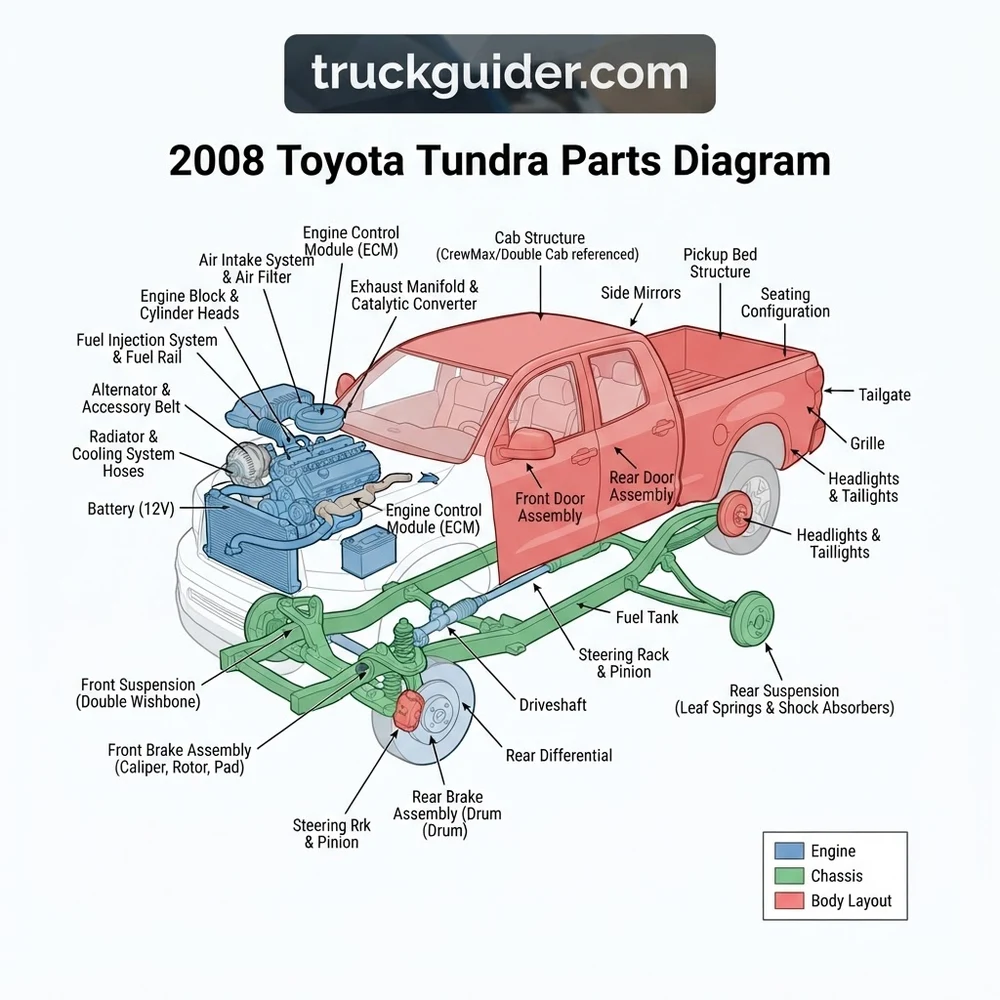
2008 Toyota Tundra Parts Diagram Layout and EPC Architecture


Factory Toyota documentation does not present vehicle components as a single, continuous blueprint. Instead, the Toyota Electronic Parts Catalog (EPC) segments the 2008 Toyota Tundra (XK50 Platform) into hierarchical component groups designed around specific production assemblies. Understanding this layout is essential when cross-referencing factory parts microfiche against real-world hardware on your bench.


The OEM parts system distributes every bolt, seal, bracket, and casting across four primary catalog divisions:
- Tool / Engine / Fuel (Group 1): Contains the complete cylinder block, cylinder head, valvetrain, intake and exhaust manifolds, fuel delivery rails, cooling system pumps, and emission control plumbing.
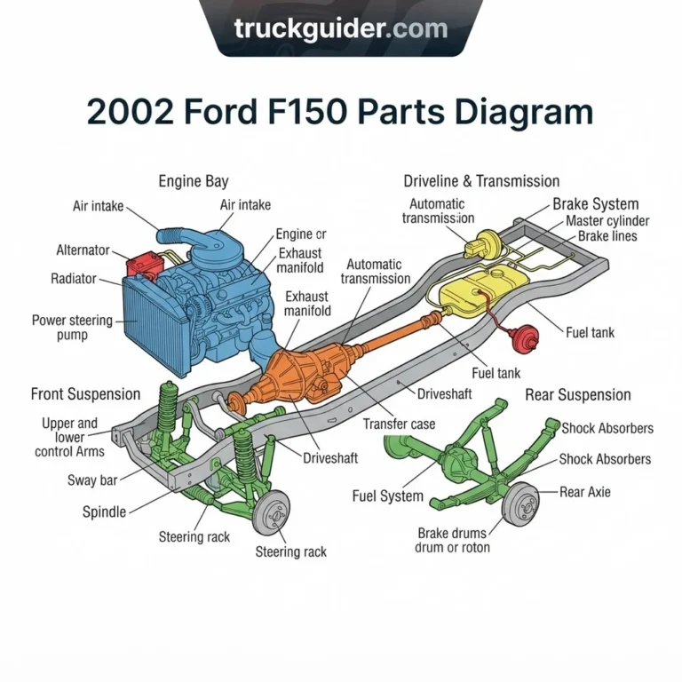
- Powertrain / Chassis (Group 2): Houses the transmission case, torque converter, internal valve bodies, transfer case, front differential, rear axle housing, propeller shafts, suspension arms, steering rack, and hydraulic brake lines.
- Body (Group 3): Details cab structural panels, glass, doors, exterior truck bed bedsides, tailgate mechanisms, interior dashboards, and seat frames.
- Electrical (Group 4): Catalogs the engine bay and cabin wiring harnesses, starter motors, alternators, engine control modules (ECMs), relays, junction fuse blocks, and lighting assemblies.
Every individual assembly diagram within these divisions utilizes a standardized drafting logic. Components are presented in an exploded perspective oriented along their actual vehicle installation axes. Assemblies enclosed within dashed or dotted boundary lines signify a serviceable unit; fasteners and internal sub-components positioned inside that perimeter can be ordered either individually or under the parent assembly callout.
Toyota tracks every item through the standardized Toyota Part Number System, which uses a 10-digit format (often extended to 12 digits for color-matched interior trim or superseded revisions). The primary structure follows a XXXXX-XXXXX syntax:
In the Toyota 10-digit schema, the first 5 digits represent the base Part Name Code (PNC), which identifies the exact functional category of the component (e.g., 16100 denotes an engine water pump across multiple vehicle platforms). The subsequent 5 digits designate the specific application design, engineering revision, and vehicle chassis parameters (e.g., 09440 for the 5.7L 3UR-FE application).
Hardware such as standard hex-flange bolts, machine screws, studs, and nuts use dedicated generic callout formats—typically starting with 90119- (bolts with captive washers), 90080- (standard hardware), or 90179- (flange nuts). When reviewing schematics, distinguishing between a vehicle-specific component callout and standard assembly hardware is critical for calculating precise thread pitches and tensile strengths.
Core System Schematics in the 2008 Toyota Tundra Parts Diagram


The mechanical architecture of the 2008 Tundra incorporates high-torque powertrains, heavy-duty running gear, and complex hydraulic circuits. To source components accurately or complete complex rebuilds, you must examine the specific engineering layouts of each core mechanical system.


Engine and Cooling System Schematics


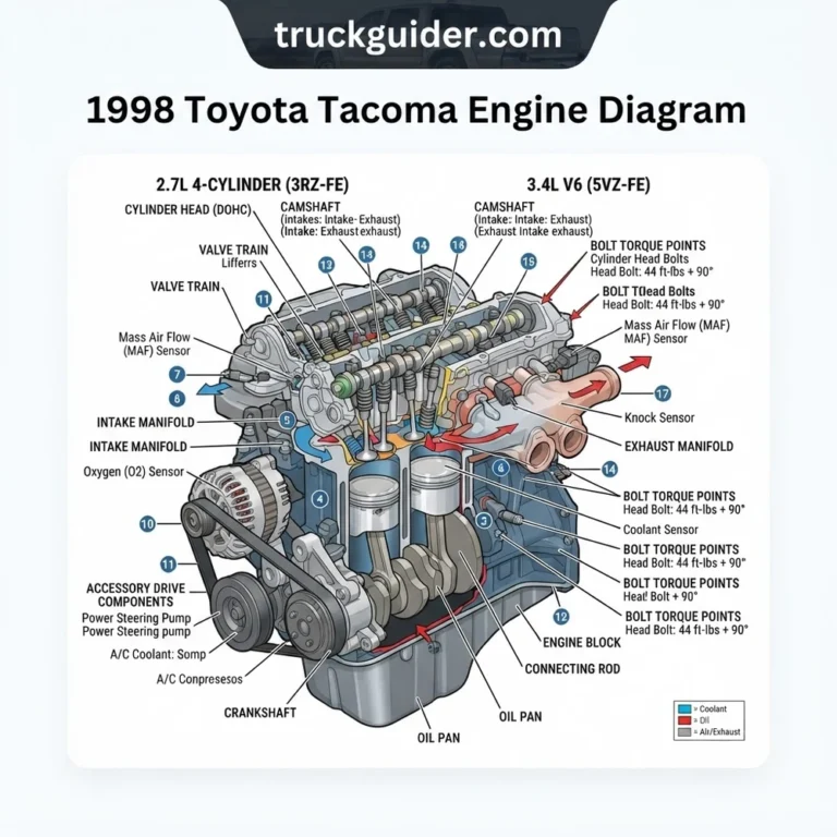
The 2008 engine catalog is split among three major configurations: the 4.0L 1GR-FE V6, the 4.7L 2UZ-FE V8 (iron block), and the 5.7L 3UR-FE V8 (aluminum block with Dual VVT-i). The cooling schematic for the 3UR-FE illustrates an aluminum water pump assembly driven by the serpentine belt, sealing against the timing chain cover via an embossed metal gasket.
When inspecting the cooling circuit layout, pay close attention to the thermostat housing location. On the 5.7L 3UR-FE, the thermostat is housed in an integrated inlet assembly positioned low on the driver side of the timing cover, whereas the 4.7L 2UZ-FE integrates it into a front-facing water crossover casting. According to OEM specs, the water pump assembly contains two distinct bolt lengths requiring specific torquing protocols to prevent warping the timing cover interface.
3UR-FE 5.7L Water Pump Fastener Torque: The M8 (12mm head) bolts require 21 Nm (15 lb-ft). The smaller M6 (10mm head) perimeter fasteners require 11 Nm (97 in-lb). Always replace the metal base gasket (PNC 16271) during any pump extraction.
The radiator schematic highlights an integrated transmission fluid cooler within the bottom tank on automatic models, accompanied by an external auxiliary fluid-to-air cooler mounted forward of the A/C condenser on vehicles equipped with the factory Towing Package. For electrical fan control schematics, consult the 2008 Tundra electrical wiring diagram (EWD) reference guide to verify fan relay actuation circuits.


Transmission and Transfer Case Driveline Schematics
The powertrain schematic features two primary automatic transmissions: the A750E/A750F 5-speed (paired with the 4.0L V6 and 4.7L V8) and the heavy-duty AB60E/AB60F 6-speed (mated to the 5.7L V8). In 4WD configurations, the transmission output shaft couples directly to the VF4BM transfer case.
The transmission exploded blueprint details the internal clutch packs, sun gear planetary sets, and the electro-hydraulic valve body. If you are servicing the valve body, the parts schematic isolates the nine pulse-width-modulated (PWM) shift solenoids. In the AB60F transfer case diagram, note the shift actuator motor assembly mounted to the rear casing. The internal schematic illustrates a dual-sprocket drive system linked by a silent-pitch multi-link chain delivering torque to the front companion flange. If performing a transmission overhaul, consult our comprehensive Aisin AB60F transmission overhaul walkthrough for clutch pack tolerance benchmarks.
Front Suspension and Steering System Blueprints
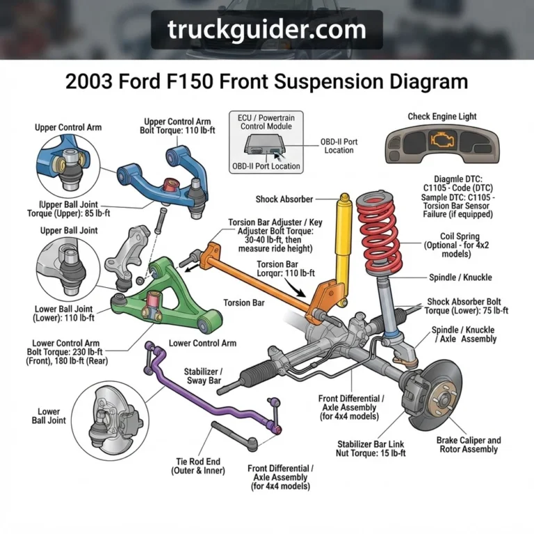
The front suspension schematic illustrates an independent double-wishbone configuration paired with high-mount upper control arms and a coil-over-shock assembly. The forged steel lower control arm mounts to the vehicle frame via dual eccentric cam bolts that govern caster and camber adjustments.
Crucial items on the front steering schematic include the power rack-and-pinion assembly (PNC 44250), equipped with an internal rotary valve. The blueprint breaks down inner tie rod ends (rack ends), outer tie rod ends, and rack mounting bushings. Pay strict attention to the steering knuckle assembly: the lower ball joint utilizes an inverted bolt flange configuration rather than a conventional press-fit ball joint.


| Suspension Component Callout | Base PNC | OEM Fastener Torque Spec |
|---|---|---|
| Lower Ball Joint to Knuckle Bolts (4 per side) | 43330 / 43340 | 153 Nm (113 lb-ft) |
| Lower Control Arm Alignment Cam Nuts | 48190 / 48198 | 280 Nm (207 lb-ft) |
| Tie Rod End Outer Ball Stud Nut | 45046 / 45047 | 92 Nm (68 lb-ft) |
| Sway Bar End Link to Knuckle Nut | 48810 / 48820 | 120 Nm (89 lb-ft) |
Rear Axle, Differential, and Leaf Spring Structure


The rear chassis schematic reveals an underslung multi-leaf spring suspension stabilizing a heavy-duty live rear axle. Shocks are arranged in a staggered configuration (one facing forward, one facing rearward) across the axle tube to counteract axle wrap under acceleration. The rear differential blueprint illustrates either a 9.5-inch ring gear assembly (standard on 4.0L/4.7L models) or a massive 10.5-inch ring gear assembly (exclusive to the 5.7L 3UR-FE). These differentials are semi-floating units with pressed-on rear wheel bearings and integral ABS tone rings.
Rear Leaf Spring U-Bolts are non-reusable fasteners. When loosening or replacing components illustrated in the rear suspension schematic, always discard the OEM U-bolts (PNC 48046) and torque the replacement nuts in an alternating cross-pattern to 135 Nm (100 lb-ft) while the vehicle rests on its suspension at curb height.
How to Read the 2008 Toyota Tundra Blueprint and Callouts


Deciphering an exploded schematic requires converting generic visual callout flags into fully qualified 10-digit OEM part numbers. Following a disciplined, sequential workflow eliminates component ordering errors and ensures you receive the correct hardware revision.
- Isolate the Base Part Name Code (PNC): Identify the item you require on the graphical illustration. Locate the numeric callout pointing to the component. Note that this number is typically a 5-digit PNC (such as
48510for the front shock absorber assembly or04465for the disc brake pad kit) rather than a complete part number. - Cross-Reference Hardware Symbols and Parent Assemblies: Examine the lines surrounding the callout. If the component sits inside a boxed frame linked to an assembly bracket, note down the assembly number if you need the entire pre-built cluster. Identify technical symbols: a solid black circle (●) adjacent to a callout designates a non-reusable component (e.g., cotter pins, crushed copper crush washers, O-rings, and stretch bolts).
- Apply the VIN Filter and Production Date Matrix: Enter the 17-digit Vehicle Identification Number into the EPC interface. The 2008 model year includes running engineering changes split by production dates (spanning November 2007 through August 2008). A VIN filter strips away inapplicable part variants governed by your specific cab configuration, engine displacement, and plant of manufacture (e.g., Princeton, Indiana vs. San Antonio, Texas).
- Map the PNC to the Full 10-Digit OEM Part Number: Using the filtered parts list corresponding to that schematic index, find your target PNC. The catalog will resolve the base code to the active 10-digit part number (e.g., PNC
04465maps to04465-04012for standard front pads). Check the remarks column for superseding part numbers that indicate improved factory revisions.
Troubleshooting Diagram Mismatches and Component Confusion


Technicians frequently encounter discrepancies between parts diagrams and real-world hardware on 2008 Tundra models. These mismatches stem from mid-cycle emissions updates, wheelbase differences, and cab dimensions.
The most common catalog confusion involves the Secondary Air Injection Pump Assembly on the 5.7L 3UR-FE. In parts catalogs, the air injection system is often indexed under “Emission Control” or “Vacuum Piping.” Diagrams illustrate two distinct air switching valves (Bank 1 and Bank 2) mounted deep in the engine valley beneath the intake manifold runners, while the electric air pumps themselves are housed low behind the front passenger-side inner fender liner. If dealing with diagnostic codes P1441 or P2440, ensure you do not order the air switching valve when the failure is caused by pump motor housing corrosion or water ingestion through the inner fender ducting.
Another frequent issue occurs in the Driveline Schematic regarding the propeller shaft. The 2008 Tundra uses different driveshaft configurations depending on wheelbase:
- Regular Cab standard beds utilize a single-piece aluminum or steel driveshaft with no center bearing.
- Double Cab and CrewMax configurations use a two-piece driveshaft assembly featuring an intermediate center support bearing (carrier bearing, PNC 37230).
Ordering parts using generic schematic illustrations without confirming wheelbase length (126.8 in, 145.7 in, or 164.6 in) results in receiving incorrect carrier brackets, slip yokes, or universal joints (U-joints). Note that OEM 2008 Tundra U-joints are staked into the yoke from the factory on some shaft revisions and are not individually cataloged, requiring replacement of the entire shaft section.
Finally, steering rack and outer tie rod ends present thread pitch variations across early and late 2008 builds. Early 2008 production units may feature inner-to-outer tie rod threads with an M14 x 1.5 pitch, whereas late 2008 revisions transitioned to an M15 x 1.5 pitch to match updated heavy-duty steering racks (PNC 44250-0C050). Always inspect the physical thread OD on the inner tie rod before referencing the schematic parts table.
2008 Toyota Tundra Configuration Matrix and Powertrain Layout
The following quick-reference matrix correlates 2008 Tundra model variants, engine codes, transmission models, chassis designations, and rear axle assemblies to streamline your catalog searches.
| Engine & Displacement | Chassis Code | Transmission | Drivetrain | Rear Differential Spec |
|---|---|---|---|---|
| 4.0L V6 (1GR-FE) | GSK50 / GSK51 | A750E (5-Speed Auto) | 4×2 Rear-Wheel Drive | 9.5″ Ring Gear / 10-Bolt Housing |
| 4.7L V8 (2UZ-FE) | UCK50 / UCK51 | A750E (5-Speed Auto) | 4×2 Rear-Wheel Drive | 9.5″ Ring Gear / 10-Bolt Housing |
| 4.7L V8 (2UZ-FE) | UCK55 / UCK56 | A750F (5-Speed Auto) | 4×4 Part-Time 4WD | 9.5″ Ring Gear / 10-Bolt Housing |
| 5.7L V8 (3UR-FE) | USK50 / USK51 / USK52 | AB60E (6-Speed Auto) | 4×2 Rear-Wheel Drive | 10.5″ Ring Gear / 12-Bolt Housing |
| 5.7L V8 (3UR-FE) | USK55 / USK56 / USK57 | AB60F (6-Speed Auto) | 4×4 Part-Time 4WD | 10.5″ Ring Gear / 12-Bolt Housing |
When ordering timing components for the 4.7L 2UZ-FE, keep in mind this engine uses a cogged rubber timing belt rather than the metal roller chains found on the 4.0L and 5.7L engines. Review the dedicated 2UZ-FE timing belt replacement technical bulletin for comprehensive tensioner, idler pulley, and cam seal schematic details.
2008 Toyota Tundra Parts Diagram Frequently Asked Questions
How do I locate the exact rear differential ring gear size on the 2008 Tundra parts schematic?
To identify whether your truck has the 9.5-inch or 10.5-inch ring gear, examine the rear axle differential carrier schematic. Vehicles equipped with the 5.7L 3UR-FE utilize the 10.5-inch carrier, identifiable by 12 bolts securing the third member to the axle housing. Models equipped with the 4.0L V6 or 4.7L V8 feature a 10-bolt mounting pattern securing a 9.5-inch differential carrier. Checking the axle code on the driver-side door jamb certification label (e.g., A01A vs. B02A) will directly correlate to the differential group in the EPC catalog.
Why does my 2008 Tundra diagram show multiple water pump part numbers for the 5.7L V8?
The 3UR-FE 5.7L water pump underwent several technical revisions to fix early coolant seepage from the mechanical shaft seal weep hole. The initial production part number (16100-09440) was superseded by 16100-09441, and ultimately updated to 16100-09442. When looking at your parts catalog, always check the “Interchangeability” or “Supersession” column; the latest alphanumeric revision fits all 2008 3UR-FE engine blocks and includes an improved shaft bearing assembly and an updated multi-layer steel mating gasket.
What does a dotted or dashed boundary line indicate around a component cluster?
In Toyota EPC blueprints, a dashed boundary line identifies a complete serviceable sub-assembly kit. Individual components inside the boundary can usually be ordered separately if they display their own distinct 5-digit PNC callout. However, if an internal clip, shim, or O-ring does not feature an individual callout number inside the box, it is exclusively available by purchasing the primary sub-assembly part number associated with the entire bracketed cluster.
How do I identify whether a fastener in the schematic is torque-to-yield or non-reusable?


Toyota assembly diagrams utilize a distinct circular legend to identify fastener serviceability. A solid black circle (●) adjacent to the part callout or a designated flag note reading “Non-reusable part” indicates that the fastener must be discarded upon removal. This applies universally to cylinder head bolts, connecting rod bolts, lower ball joint mounting bolts, and rear leaf spring U-bolts, which deform plastically upon reaching their final torque and angle specifications.
Where is the Secondary Air Injection System indexed in the 2008 catalog index?
The Secondary Air Injection System is not located under the electrical wiring or intake manifold tabs. Within the Toyota Electronic Parts Catalog, you must navigate to Group 1 (Engine / Fuel) and select the section labeled Vacuum Piping (System 17-08) or Emission Control System. There you will locate the exploded view of the electric air pumps, intake air tubes, relay blocks, and the vacuum-actuated check valves mounted adjacent to the rear engine bellhousing.
Step-by-Step Guide to Understanding the 2008 Toyota Tundra Parts Diagram
Identify – Filter the vehicle schematic using the 17-digit VIN to establish the correct cab, bed, and drivetrain configuration.
Locate – Select the primary sub-assembly group within the parts catalog, pinpointing the physical section such as the front suspension structure or fuel delivery system.
Reference – Inspect the exploded assembly illustration and record the 5-digit PNC callout numbers for the primary component and surrounding mounting hardware.
Connect/Route – Align replacement lines, wire harnesses, or structural brackets to match the exact physical layout and orientation shown in the schematic.
Verify – Cross-check fastener sizes, clip locations, and factory torque values against the mechanical schematic before completing reassembly.
Troubleshoot – If parts do not align, re-verify the diagram index for supersessions, model year splits, or trim differences (e.g., 2WD vs. 4WD).