2009 GMC Sierra Fuse Box Diagram: Component Identification 2026

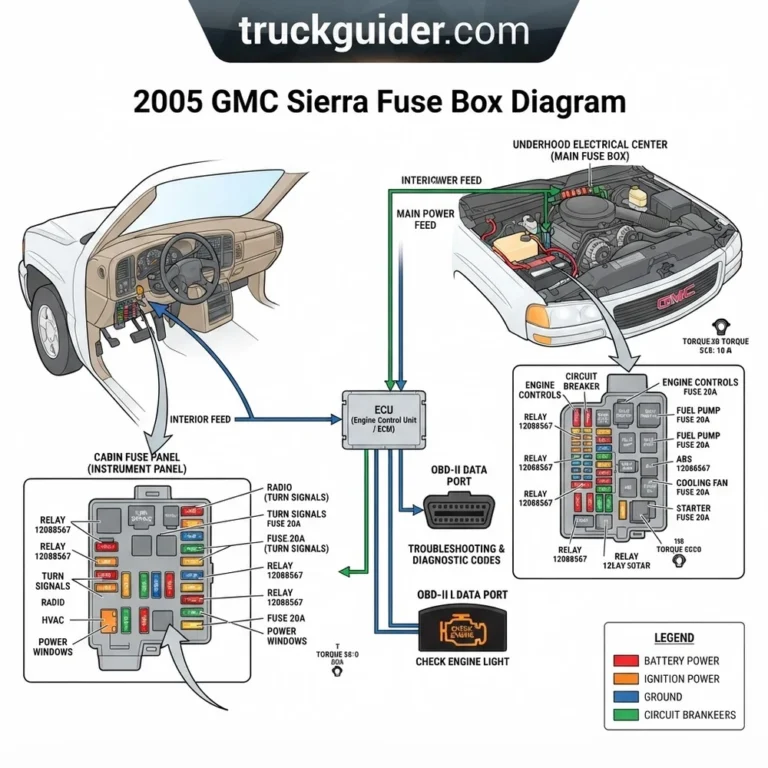
The 2009 GMC Sierra features two main fuse blocks: the underhood fuse center located on the driver-side fender near the battery, and the interior instrument panel fuse block behind the driver-side end cap. The underhood box houses high-amperage JCASE fuses and mini-relays powering the ECU, starter, and cooling fans.
📌 Key Takeaways
- Underhood fuse block cover provides the exact layout, relay positions, and amperages from 10A to 60A.
- Crucial fuses: ECM/ECU (Fuse 56 – 15A), Fuel Pump (Fuse 20 – 20A), and Injectors (Fuse 17/18 – 15A).
- Battery terminal cable nut torque spec is 13 Nm (115 lb-in); underhood fuse block mounting bolts torque to 6 Nm.
- Fretting corrosion and cracked circuit board terminals under the main underhood block frequently trigger intermittent no-starts.
- Perform simple fuse replacements DIY, but seek a professional if multiple modules fail or the diagnostic code indicates harness melt.
Electrical diagnostics on the GMT900 platform require an exact understanding of system power distribution. The 2009 GMC Sierra 1500, 2500HD, and 3500HD utilize an integrated electrical distribution architecture split between an Underhood Bus Electrical Center (UBEC) and an interior Instrument Panel junction block. Whether you are tracking a parasitic drain, resolving a no-crank condition, or diagnosing communication dropouts across the high-speed Controller Area Network (CAN-bus), referencing an accurate 2009 GMC Sierra fuse box diagram is fundamental to pinpointing circuit faults. This technical guide outlines fuse and relay designations, testing procedures, amperage ratings, and terminal routing to maintain vehicle electrical integrity.
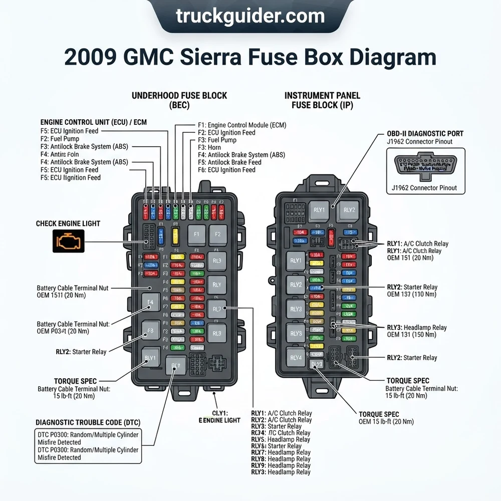
2009 GMC Sierra Fuse Box Diagram: Panel Locations and Schematics


The 2009 GMC Sierra distributes electrical loads across two primary fuse blocks. Power routing originates at the primary 12-volt battery and flows through high-amp fusible links and JCase cartridges before stepping down to low-draw cabin functions. Accessing these panels requires no specialized tools, but proper panel separation techniques prevent moisture ingress and mechanical damage to internal bus bars.



Underhood Fuse Block Terminal Lugs (Stud 1 / Stud 2): M6 Nut: 9–10 Nm (80–89 lb-in); M8 Battery Cable Nut: 15 Nm (133 lb-in). Tightening beyond OEM torque spec fractures the glass-filled nylon housing and induces internal micro-cracks in the lead frame.
Underhood Fuse Block (UBEC) Engine Compartment Layout


The primary power distribution center sits on the driver-side inner fender, adjacent to the battery and master cylinder cowl. It features a four-point latching cover engineered to seal against heat, road spray, and chemical exposure. Beneath the weather-sealed top cover rests the multi-layer printed lead-frame assembly. Four 7mm hex bolts retain the upper fuse block into the lower wire harness connectors. If full panel removal is required during a harness replacement or back-probing procedure, refer to verified chassis ground strap locations to eliminate false continuity readings.
The UBEC distributes unfused battery positive voltage (B+) directly from the positive cable terminal lug to high-current systems, including the starter solenoid, anti-lock braking system (ABS), cooling fan modules, and the Body Control Module (BCM). It also acts as the central mounting station for the ISO micro-relays and mini-relays controlling the powertrain, lighting, and air conditioning compressor clutch.
Instrument Panel Fuse Block (Interior Dashboard Center)
The interior electrical junction sits behind an access door on the driver-side outboard end-cap of the instrument panel. Open the driver door completely to reveal the access cover, then pull outward firmly on the integrated finger pocket to release the retaining clips. A secondary auxiliary panel is present on select heavy-duty trim levels on the passenger-side dashboard end, housing factory-upfitted switches and auxiliary pass-through circuits.
This interior junction block works closely with the BCM, which is mounted directly beneath the steering column cowl. The instrument panel fuses safeguard micro-current sensory circuits, instrument cluster instrumentation (IPC), interior LED/incandescent lighting, pedal adjusters, power windows, and serial data links. High-amperage lines do not pass directly into this box; rather, it receives downstream, relay-switched B+ voltage from the underhood distribution center.


Deciphering the Fuse Block Cover Schematic
The inner face of both fuse block access covers features a stamped or laser-screened cavity guide. Each circuit features an alpha-numeric index coordinating with cavity rows and columns. In OEM GM schematics, each fuse position is assigned a three- to four-digit cavity identifier alongside its colloquial circuit abbreviation (e.g., “ECM 1,” “INJ A,” or “LTR”). The legend groups components by type: standard rectangular blocks signify micro/mini blade fuses, square blocks designate JCase cartridge fuses, and large rectangular footprints denote plug-in relays.
When cross-referencing your physical fuse layout against the schematic, identify the physical orientation notch or master mounting stud first. Rotating the schematic by 180 degrees is a frequent diagnostic mistake that leads to pulling an operational transmission control fuse rather than the targeted ignition circuit.
Blade-Type Mini Fuses and High-Current JCase Cartridges


The 2009 Sierra relies on two mechanical fuse styles conforming to ISO 8820-3 standards:
- ATM Mini-Blade Fuses (2A to 30A): Utilize standard color coding (e.g., Tan for 5A, Red for 10A, Blue for 15A, Yellow for 20A, Clear for 25A, Green for 30A). These provide overcurrent protection for solid-state controllers and lighting. Exposed probe points on the top face allow voltage drop and continuity testing without unseating the component.
- JCase High-Profile Cartridge Fuses (20A to 60A): Employed on heavy inductive loads such as the ABS pump motor, electric trailer brake system, engine cooling fans, and cabin blower motor. These feature clear-top viewports to permit visual inspection of the fusible element matrix.
Critical Engine and Cabin Circuits in the 2009 Sierra Fuse Block


Power delivery across the GMT900 platform divides functional circuits into ignition-switched (Run/Crank or Accessory) and unswitched continuous battery voltage (B+). The table below lists the mission-critical fuses and relays within the 2009 GMC Sierra fuse box diagram, spanning the underhood center and the cabin panel.


| Fuse/Relay ID | Rating (Amps) | Panel Location | Protected Circuit / Load Function |
|---|---|---|---|
| ECM (Fuse 56) | 15A Mini | Underhood | Engine Control Module (ECM) Battery Feed, Mass Air Flow |
| ECM 1 (Fuse 43) | 15A Mini | Underhood | PCM/ECU Switched Ignition Power, Transmission Controller |
| INJ A (Fuse 34) | 15A Mini | Underhood | Fuel Injectors & Ignition Coils – Bank 1 (Odd: 1, 3, 5, 7) |
| INJ B (Fuse 35) | 15A Mini | Underhood | Fuel Injectors & Ignition Coils – Bank 2 (Even: 2, 4, 6, 8) |
| F/PMP (Fuse 57) | 20A Mini | Underhood | Fuel Pump Driver Module / In-Tank Fuel Pump Assembly |
| FSCM (Fuse 21) | 20A Mini | Underhood | Fuel System Control Module Logic Power |
| STUD 1 (Fuse 68) | 40A JCase | Underhood | Trailer Wiring 12V B+ Battery Charge Circuit / Upfitter Aux |
| STUD 2 (Fuse 69) | 30A JCase | Underhood | Heavy Duty Trailer Brake Controller (ITBC Module) |
| FAN 1 (Fuse 71) | 40A JCase | Underhood | Engine Cooling Fan Motor 1 (Primary Radiator Coolant Flow) |
| FAN 2 (Fuse 70) | 40A JCase | Underhood | Engine Cooling Fan Motor 2 (Secondary High-Temp Draw) |
| LTR / AUX (Fuse 2) | 20A Mini | Instrument Panel | Cigarette Lighter, DLC / OBD-II Diagnostic Port Pin 16 |
| AUX PWR 2 | 20A Mini | Instrument Panel | 12-Volt Center Console Accessory Power Outlet |
| BCM (Fuse 1) | 15A Mini | Instrument Panel | Body Control Module Unswitched Power Input (Logic Core) |
| IPC (Fuse 18) | 10A Mini | Instrument Panel | Instrument Panel Cluster, Driver Information Display |
| RUN / CRNK | 10A Mini | Instrument Panel | Crank Signal Ignition Feed to ECM, TCM, and Fuel System |
Powertrain and Engine Management (PCM/ECM & TCM)
The Powertrain Control Module (E38 for V8 gas engines, E67 for V6, and E86/LMM for Duramax Diesel) relies on constant clean battery voltage via Underhood Fuse 56 (15A) to maintain volatile memory, such as learned fuel trim algorithms and idle air control offsets. When ignition switches to the RUN position, Fuse 43 energizes the internal ECM output driver stages. If current fluctuations occur, the ECM cannot regulate the electronic throttle body or fuel injector timing, prompting fail-safe engine shutdown modes.
The ignition coil circuits (INJ A and INJ B) provide independent 15A paths per cylinder bank. Isolating the banks through separate fuses ensures that a dead-shorted coil on cylinder 3 will not compromise the power feed to Bank 2. If a fuel heater or glow plug controller is required for diesel models, an auxiliary pre-heat maxi-fuse block mounts directly to the positive battery clamp terminal, operating at 125A to 175A.
Body Control Module (BCM) and Cabin Operations
The BCM acts as the central coordinator for the vehicle’s low-speed Class 2 / GM-LAN serial lines. It commands the Retained Accessory Power (RAP) relay, which keeps systems active between engine shut-off and door opening. The interior instrument panel block routes power to the BCM via discrete branch fuses: BCM 1 through BCM 5. These separate circuits protect interior lamp drivers, security key transponder recognition, power door locks, and remote keyless entry antennas.
12-Volt Accessory Power Outlets and OBD-II Link
Pin 16 of the standardized OBD-II Diagnostic Link Connector (DLC) receives continuous unswitched 12-volt battery power from the instrument panel LTR/AUX 20A fuse (Fuse 2). If an external 12V phone charger plugged into the front dash lighter socket shorts out, this fuse opens instantly. As a direct result, diagnostic scan tools cannot power up when connected to the truck, preventing technicians from reading diagnostic codes or reading live sensor data streams.


Heavy-Duty Tow Package and Trailer Brake Subsystems


For trucks equipped with the Z82 trailering package, two high-current studs occupy the front edge of the underhood block. Stud 1 (40A JCase) provides auxiliary 12V charging power to the seven-way RV blade harness at the rear bumper. Stud 2 (30A JCase) feeds the Integrated Trailer Brake Controller (ITBC) module mounted inside the cab. From the factory, the red/black B+ eyelet harness wire under the brake master cylinder is left untethered; installing this eyelet on Stud 1 activates the rear charge line.
Never bridge blown JCase or mini fuses using heavier gauge wire or higher-amperage replacements (e.g., swapping a 15A for a 30A). The GMT900 instrument harness uses thin 0.35 mm² to 0.5 mm² cross-section copper core wiring. An over-amperage condition will cause the wire loom to melt before the higher-rated fuse opens, leading to severe thermal dashboard fires.
Electrical Symptoms: Blown Fuses, Relays, and Check Engine Light


Isolating circuit defects within the 2009 GMC Sierra requires linking physical vehicle symptoms to fuse block internal fault lines. Because the instrument cluster, powertrain controller, and transmission controller share bidirectional multiplexed networks, an open circuit in a single power feed generates cascading system anomalies.
- Total Loss of Scan Tool Communication: When an OBD-II scanner displays a “Communication Error” or fails to illuminate upon plug-in, the cause is almost universally a blown 20A LTR/AUX fuse in the dashboard box. The diagnostic tool relies on DLC Pin 16 for circuit board power and Pin 4/5 for ground. Verify continuity across this fuse before assuming an ECU failure.
- Engine Cranks Without Firing (No-Start Condition): If the starter motor engages properly but the engine turns over continuously without combustion, verify underhood Fuse 57 (20A Fuel Pump) and the Fuel Pump Relay (Relay 56). Additionally, check the FSCM Fuse (20A) which powers the rear chassis-mounted fuel control module. Without module illumination, the high-pressure mechanical or in-tank electrical pump stays idle, registering zero fuel rail pressure.
- Check Engine Light Accompanied by P0601, U0100, or Actuator Codes: An unseated or oxidatively degraded ECM 1 fuse can starve the powertrain module during cold cranking, triggering erratic system operation. This leads to diagnostic code U0100 (Lost Communication with ECM/PCM) or active symptoms of limp mode failure. Blown heater circuit fuses (O2 A and O2 B) routinely set persistent codes P0135, P0141, P0155, and P0161, which directly illuminate the check engine light.
- Erratic Oil Pressure Gauge or Cluster Fluctuations: The GMT900 instrument panel cluster (IPC) calculates the display position of the oil pressure gauge using digital CAN data sent from the ECM. If the IPC logic fuse drops voltage below 10.5V due to high terminal resistance, the cluster can reset intermittently, pegging the oil pressure sweep to zero and sounding the low oil pressure warning chime, despite normal mechanical engine pressure.
- Engine Overheating Due to Inactive Electric Cooling Fans: The engine cooling system relies on a dual-fan assembly controlled through three high-amp relays (Fan Low, Fan High, Fan S/P). If JCase Fuse 70 or 71 opens, the fans will not trigger at 221°F (105°C), blocking crucial radiator coolant flow. This leads to rapid thermal expansion, coolant boil-over, and severe mechanical cylinder head warping.
- Brake Transmission Shift Interlock (BTSI) Lockup: Inability to shift out of “PARK” with the brake pedal depressed points to a failed STOP LP fuse (20A) in the underhood block. This single open circuit cuts output to the rear brake lamps and removes the release signal required by the BTSI shift-lock solenoid located on the steering column.
How to Test 2009 GMC Sierra Fuse Box Diagram Circuits Step-by-Step


Diagnosing an electrical failure by randomly pulling fuses is inefficient and can corrupt memory tables within the vehicle modules. Using a standardized testing sequence with a high-impedance Digital Multimeter (DMM) prevents unnecessary electrical disruption.
Always run electrical tests with a fully charged battery holding a minimum of 12.6V resting potential. Low system voltage causes false resistance readings and intermittent module dropouts across the 2009 GMC Sierra network.
- Establish Standard Testing Parameters: Shift the Sierra transmission to PARK, apply the parking brake, and verify the ignition switch is set to Key-On Engine-Off (KOEO). This powers all hot-in-run bus tracks. Connect the black negative probe of your digital multimeter to a clean, unpainted chassis ground or the negative battery terminal clamp.
- Execute In-Situ Voltage Drop Across Mini-Blade Fuses: Set the DMM to DC Volts (20V scale). Without removing the fuse from its socket, place the red meter probe into the small metallic test pad on one side of the fuse’s top surface. Read the voltage, then transfer the probe to the second test pad on the same fuse. A functional circuit will read identical battery voltage on both pads (e.g., 12.4V to 12.6V). If one side reads 12.4V and the other side registers 0.0V, the internal fuse link is open and blown.
- Extract Suspect Fuses Using the OEM Extraction Tool: Use the plastic fuse puller stored in the upper lid of the UBEC. Clamp the jaw of the tool squarely around the shoulder of the mini-blade fuse and pull straight upward along the pin axis. Wiggling the fuse side-to-side will widen the terminal female spring clips inside the fuse block, leading to fretting corrosion and high intermittent resistance.
- Verify Continuity with an Ohmmeter: Switch the meter to Resistance (Ohms, Ω scale). Touch the probes across the two exposed blades of the extracted fuse. A standard functional fuse should register nearly zero resistance (0.1 to 0.3 Ω). A reading of “O.L.” (Open Loop) or infinite resistance confirms an internal failure.
- Inspect JCase Cartridge Terminals: To test JCase fuses (such as trailer towing or ABS circuits), shine a high-output LED light through the transparent plastic top cover. Look for a hairline gap or carbon soot traces across the central serpentine link. If visual confirmation is inconclusive, insert narrow back-probe pins into the side access test slots to read DC voltage drops across the internal bridge.
- Test Relay Circuit Pinouts: To verify a micro-relay (such as the A/C or Starter Relay), extract the relay from the block and refer to the international standard pin designations stamped on its underside base:
- Pin 85 and Pin 86: Control Coil circuit (must show 70–110 Ω across coil terminals).
- Pin 30: Constant Battery B+ feed from the upstream fuse.
- Pin 87: Load output line traveling to the managed accessory.
- Pin 87a (if equipped): Normally closed contact path.
Use a fused jumper lead (incorporating an inline 10A fuse) to bridge cavity 30 and cavity 87. If the managed accessory runs immediately (e.g., the starter clicks or the horn sounds), the high-current side of the circuit is operational, isolating the fault to the relay coil, trigger switch, or ECM control driver.
Frequently Asked 2009 GMC Sierra Fuse Box Diagram Questions
Why does my OBD-II scanner say “No Communication” or refuse to turn on?
Pin 16 on the 16-pin diagnostic connector supplies battery power directly to external code readers and flash tuners. In the 2009 GMC Sierra, this pin shares a circuit with the 20A LTR / AUX fuse located in the instrument panel fuse block. If an auxiliary accessory or charging plug causes this fuse to blow, the port drops its 12V output. Replacing this 20A mini-fuse restores communication to the scan tool, allowing you to extract pending diagnostic codes or complete system readiness checks.
Which fuse controls the fuel pump in a 2009 GMC Sierra?
The fuel delivery system uses two primary circuits in the underhood block: Fuse 57 (20A, labeled F/PMP) and Fuse 21 (20A, labeled FSCM). On GMT900 trucks equipped with electronic Fuel System Control Modules, power routes through Fuse 21 to the solid-state controller mounted above the spare tire, which then drives the in-tank pump via pulse-width modulation. On non-FSCM configurations, power routes directly through Relay 56 and Fuse 57. Always test both circuits when diagnosing an engine crank/no-start symptom.
What causes the Underhood Fuse Block to fail internally on 2009 trucks?
The GMT900 Underhood Electrical Center uses a layered plastic housing that encases stamped copper trace plates. Over time, engine compartment thermal cycling causes this layered housing to warp. Additionally, vibration can cause the four 7mm underhood harness mounting bolts to back out, resulting in micro-arcing and terminal fretting corrosion. This damage typically surfaces as erratic electrical issues, such as random cluster warnings or multiple actuator circuit codes occurring at the same time.
Can a blown fuse trigger a false oil pressure gauge drop or engine timing code?


Yes. The ECM relies on stable reference voltages to read the oil pressure sensor and camshaft position sensors accurately. If an underlying power feed fuse (such as ECM 1 or ENG 1) develops high internal resistance across an oxidized blade, the supply voltage to these critical engine sensors can fluctuate below 4.75 volts. This voltage instability can cause the cluster needle to drop or trigger erratic DTCs like P0521 (Oil Pressure Sensor Performance) or camshaft timing chain correlation codes, even when mechanical lubrication and engine valve timing remain within manufacturer tolerances.
How do I identify which fuse powers the trailer brake controller?
Trailer brake operations rely on Underhood Fuse 69 (labeled STUD 2), a 30A high-profile JCase fuse. This circuit routes directly to the blunt-cut wiring harness beneath the driver-side dashboard or directly powers the factory-installed Integrated Trailer Brake Module (ITBC). If this fuse is blown or unseated, your Sierra will