2011 Chevy Silverado Front Bumper Diagram: 2026 Repair

The 2011 Chevy Silverado front bumper system mounts a steel face bar to the frame horns via two primary impact brackets using four 18mm bolts torqued to 45 ft-lbs. Outer support braces secure each corner to the subframe using 15mm hardware, while the upper bumper cap clips into the grille layout.
📌 Key Takeaways
- Primary frame-to-bumper impact brackets utilize four M12 (18mm head) bolts torqued to 45 ft-lbs.
- Outer bumper corner support braces require 15mm socket hardware and align the side fascia to fenders.
- Disconnect the fog lamp sub-harness connector behind the driver-side bumper horn before unbolting.
- Common structural sag occurs when plastic upper cap retainer clips fatigue or impact bar brackets bend.
- Minor realignment and hardware replacement are DIY-friendly; bent frame horns require a professional frame rack.
The GMT900 platform utilized on the 2011 Chevrolet Silverado features a modular front bumper architecture engineered to balance structural impact absorption, aerodynamic efficiency, and powertrain cooling. Whether servicing a work truck with standard stamped steel face bars or an LTZ trim equipped with integrated fog lamps and painted impact covers, understanding the exact mechanical layout is essential. The bumper assembly does not simply bolt directly to the frame in a static orientation; it relies on a dynamic network of crush horns, diagonal corner stiffeners, slotted impact brackets, and thermoplastic retainers. This technical guide and schematic breakdown deconstructs the 2011 Chevy Silverado front bumper assembly into individual serviceable components, outlines exact factory teardown and installation procedures, provides torque and fastener specifications, and diagnoses common structural alignment failures.
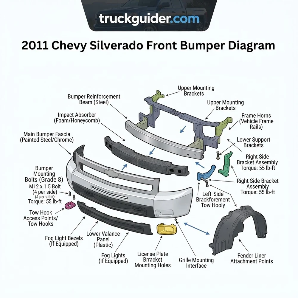
2011 Chevy Silverado Front Bumper Diagram: Component Breakdown and Schematic Layout


The front bumper system on the 2011 Silverado 1500 comprises a three-tier configuration: an upper cosmetic transition cap, a heavy-gauge central steel face bar, and a lower aerodynamic ground-effects valance. Beneath these exterior components lies an engineered sub-structure of stamped steel mounting brackets designed to transfer low-speed impact loads directly into the hydroformed front frame rails while isolating the radiator core support.



| Diagram ID / Component | OEM Part Reference | Material & Construction | Fastener Specs & Fastening Type | Structural Function |
|---|---|---|---|---|
| Bumper Face Bar | GM 25883349 (Chrome) GM 25883355 (Paint to Match) |
Cold-rolled stamped steel (gauge 14) | Four M12x1.75 carriage bolts / flange nuts | Primary kinetic load distribution; central anchoring structure |
| Upper Bumper Cap / Fascia Cover | GM 15894294 (Textured) GM 25883344 (Smooth) |
Thermoplastic Olefin (TPO) | Molding clips & plastic push-retainers (GM 11519444) | Aerodynamic transition from bumper bar to front grille and headlamps |
| Lower Valance / Air Deflector | GM 15224193 (Standard) GM 20942544 (Extended) |
High-density polyethylene (HDPE) | Interlocking integral tabs & multi-finger push nuts | Manages underbody airflow to reduce aerodynamic drag and direct air to radiator |
| Central Frame Mounting Brackets | GM 15131299 (LH) GM 15131300 (RH) |
Heavy stamped steel bracketry (5mm thick) | M12x1.75 grade 10.9 bolts (18mm socket head) | Connects bumper face bar directly to frame horn node plates |
| Outer Bumper Support Braces | GM 15849852 (LH) GM 15849853 (RH) |
Tubular/stamped diagonal strut | M10x1.5 hex flange bolts (15mm socket head) | Stabilizes outer bumper wings against aerodynamic flutter and road vibration |
| Front Recovery Tow Hooks | GM 15263006 | Forged solid carbon steel | M12 through-frame cross bolts (18mm head / 19mm nut) | Chassis recovery point anchored through lower valance ports |
| Fog Lamp Housings (Optional) | GM 25883245 (LH) GM 25883246 (RH) |
Polycarbonate lens / PBT housing | Three T15 Torx fasteners directly into face bar brackets | Auxiliary roadway illumination integrated into lower face bar cutouts |
The primary load-bearing foundation is the Bumper Face Bar. Manufactured from high-tensile stamped steel, this component acts as the visual midpoint and the structural transverse beam of the assembly. The face bar incorporates dedicated punch-outs on designated option packages to host the round factory fog lamps. Integrated directly above the steel face bar is the Upper Bumper Cap / Fascia Cover, often referred to as the bumper filler. The upper cap spans the gap between the headlights, center grille, and lower fenders. It utilizes snap-fit directional retaining tangs along its lower perimeter that wedge into matching rectangular receivers stamped directly along the upper ridge of the steel face bar.
Attached to the lower edge of the steel face bar is the Lower Valance / Air Deflector. Held in place by push-retainer hardware and integral locking tabs, this deflector prevents high-pressure frontal air from passing under the vehicle, forcing it instead through the heat exchangers. Technicians who service auxiliary electrical systems will find the factory lighting harnesses tied directly behind this assembly, and reviewing a fog light harness wiring diagram is recommended when inspecting wire loom routing adjacent to these mounting tabs.
The entire aesthetic assembly relies on the Frame Mounting Brackets (Inner Impact Brackets) and the Outer Bumper Support Braces for chassis anchoring. The inner brackets interface directly with the vertical face plates of the hydroformed frame horns. These brackets feature slotted bolt passages that grant horizontal and vertical adjustability during assembly. Conversely, the outer support braces act as cantilever struts; they extend laterally from the outboard edges of the frame rail back to the curved corners (wings) of the steel face bar. Without these diagonal braces, the outer bumper edges experience cyclical oscillation at highway speeds, resulting in fatigue failure of the plastic clips holding the upper fascia cap.
The bumper face bar and inner brackets utilize slotted mounting apertures rather than fixed circular holes. This design accommodates minor chassis manufacturing tolerances across the GMT900 platform, requiring manual leveling and gap adjustment whenever the assembly is dismounted.
Step-by-Step 2011 Silverado Front Bumper Removal and Disassembly Blueprint


Removing the complete front bumper system on the 2011 Silverado requires dismounting the assembly as a unified module before executing sub-component bench disassembly. Performing this procedure without removing the center front grille assembly risks fracturing the brittle retention tabs on the upper bumper cap.


Required Tool Manifest

- 3/8-inch and 1/2-inch drive ratchets
- 10mm shallow and deep metric sockets
- 15mm metric socket and open-end combination wrench
- 18mm heavy-duty deep impact socket
- T15 Torx driver
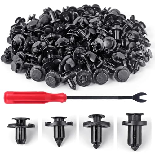
- Automotive fastener trim pad clip removal tool (fork tip)
- Floor jack and jack stands or adjustable under-hoist support stands
- Masking tape (to protect painted fender corners)
Chronological Disassembly Sequence
- Isolate Electrical Circuits: Switch the vehicle ignition to OFF. Disconnect the negative battery terminal using a 10mm wrench to prevent accidental shorting when uncoupling lighting connections. Locate the primary fog lamp harness connector (if equipped) positioned along the driver-side frame rail horn and separate the weather-pack inline connector by lifting its mechanical CPA (Connector Position Assurance) lock tab.
- Remove the Upper Radiator Sight Shield: Open the hood to expose the black plastic engine compartment sight shield. Using a trim clip removal tool, extract the eight (8) push-pin retainers securing the shield to the upper radiator core support. Pull the center pin upward first, then extract the anchor collar. Set the shield aside.
- Dismount the Front Grille Assembly: Using a 10mm socket, extract the four (4) metric hex-head screws running along the top mounting flange of the front grille. Grasp the grille firmly at the lower center and sides, then pull straight forward to disengage the four (4) spring-steel snap clips anchoring the bottom of the grille into the radiator core support brackets. Inspect the clips to ensure none remained stuck inside the support slots. Set the grille assembly aside on a clean, padded surface.
- Detach Lower Wheel Well Splash Shields: Turn the front wheels inward to gain clearance to the wheel arch liners. Using a 10mm socket and trim removal tool, extract the two (2) fasteners per side that tie the forward edge of the thermoplastic wheel well splash shields to the outer ends of the bumper corner brackets. Peel back the splash shield to visually access the outer bumper diagonal support braces.
- Unbolt the Outer Bumper Support Braces: Working through the wheel well opening or from beneath the front quarter panels, locate the diagonal steel support brace running from the frame rail out to the corner of the bumper face bar. Using a 15mm socket and open-end wrench, remove the two (2) 15mm hex bolts anchoring the strut to the outer bumper wing. Repeat this operation on the opposite side. Leave the frame-side bolts hand-tight to allow the struts to swing clear.
- Support the Weight of the Bumper: The fully dressed front bumper assembly weighs approximately 45–55 lbs (20–25 kg). Position a hydraulic transmission jack or two adjustable work stands directly beneath the central lower section of the steel face bar to support its mass and prevent dropped hardware or damage to the paintwork on the lower fender edges. Apply automotive masking tape along the forward edge of the steel fenders where they meet the upper bumper cap.
- Extract the Primary Frame Horn Impact Bracket Bolts: With the grille removed, locate the top of the two central frame horn brackets accessed through the opening between the core support and bumper face bar. Using an 18mm socket on a long extension, extract the two (2) upper vertical mounting bolts. Next, drop underneath the bumper and locate the two (2) lower horizontal 18mm bolts securing the lower flange of the impact brackets to the front frame horn node plates. Carefully back these bolts out while supporting the bumper structure.
- Extract the Complete Bumper Assembly: With all four primary 18mm frame bolts and both outer 15mm brace bolts removed, carefully pull the entire bumper assembly forward and away from the truck. Slide the inner mounting brackets off the frame horn guide lips. If removing standard tow hooks, refer to a dedicated Silverado tow hook installation guide to verify frame cross-bolt clearances.
- Bench Disassembly of Bumper Components: Place the bumper assembly face down on a padded work surface:
- Lower Valance Removal: Disengage the perimeter snap tabs by squeezing the expansion ears with pliers and pushing them outward through the face bar slots.
- Upper Cap Disassembly: Reach behind the face bar to release the series of plastic directional tabs locking the upper cap into the top edge of the steel bar. Use a flat-blade trim tool to carefully depress each locking pawl in sequence from the driver side to the passenger side.
- Fog Lamp Extraction: If replacing fog lamps, remove the three (3) T15 Torx fasteners securing each lighting capsule directly to its stamped steel cradle bracket.
- Inner Bracket Separation: To swap the chrome or painted face bar, remove the four (4) 18mm nuts that join the inner impact brackets to the rear-facing studs of the bumper face bar.
Do not remove the lower horizontal frame horn bolts while unbolted from the top without adequate auxiliary support beneath the center face bar. The structural assembly will pivot downward instantly, risking crushing injuries or creasing the sheet metal on the forward tips of the steel front fenders.
Factory GM Torque Specifications for 2011 Silverado Front Bumper Hardware:
• Central Frame Horn-to-Impact Bracket Bolts (18mm): 85 lb-ft (115 Nm)
• Outer Support Brace Bolts (15mm): 37 lb-ft (50 Nm)
• Face Bar-to-Bracket Carriage Nuts (18mm): 55 lb-ft (75 Nm)
• Grille Assembly Upper Retaining Screws (10mm): 89 in-lbs (10 Nm)
• Recovery Tow Hook Frame Cross-Bolts (18mm): 65 lb-ft (88 Nm)
Silverado 1500 vs. 2500HD Bumper Configuration and Frame Structure


A frequent point of confusion during front-end repairs or custom conversions involves the interchangeability between light-duty (1500) and heavy-duty (2500HD/3500HD) front bumper assemblies within the 2011 model year. Both vehicles share the overarching GMT900 body architectural philosophy, but their underlying chassis geometry and thermal heat-exchange configurations differ significantly.
| Structural & Aesthetic Feature | Silverado 1500 (Light Duty) | Silverado 2500HD / 3500HD (Heavy Duty) | Cross-Compatibility Impact |
|---|---|---|---|
| Frame Horn Node Profile | Flatter vertical plane; lower relative frame height from ground | Taller vertical profile; frame rails sit 2 inches lower relative to body mounts | Direct bolt-on failure: brackets do not align to frame horns without modification |
| Center Cooling Air Slot | Solid steel face bar across the central span (no cutout) | Includes a 2-inch horizontal cooling slot stamped in the center bar | HD bar provides high-flow auxiliary induction for heavy cooling packages |
| Upper Cap Profile & Depth | Deeper, flatter plastic cap; sits flush with lower 1500 grille edge | Thinner vertical profile; stepped to clear the dropped HD hood and taller grille | Interchanging leaves an unsightly 2-inch vertical gap beneath the 1500 grille |
| Face Bar Overall Height | Narrower face profile (approx. 9.5 inches vertically at center) | Taller face profile (approx. 11.25 inches vertically at center) | HD bumper projects lower to maintain mandated DOT bumper-height compliance |
| Grille Sub-Frame Interfacing | Grille lower retaining clips lock to central core support bracket | Grille is taller overall and locks deeper into lowered forward framework | Grilles and bumper caps cannot be mixed between 1500 and 2500HD lines |
The primary mechanical driver for these differences is the distinct front frame architecture. The 2500HD and 3500HD chassis employ a boxed, high-strength steel front clip with dropped front frame rails designed to accommodate the tall physical packaging of the Duramax Diesel engine, Allison transmission, and massive stack of heat exchangers. Those servicing these components should consult a detailed GMT900 cooling system schematic to understand airflow routing.
Because the HD frame rails drop lower relative to the cab and bed line, GM altered the bumper face bar geometry and bracket drop-distance on heavy-duty models. A 2011 Silverado 2500HD bumper mounted to a 1500 truck will sit too low, leaving an extreme gap between the headlights and the bumper cap, while the mounting holes in the 1500 frame horns do not match the HD impact bracket bolt circle. Performing an “HD front-end conversion” requires replacing the bumper face bar, inner brackets, outer braces, upper bumper cap, front grille assembly, and the elevated HD steel hood simultaneously.



Troubleshooting 2011 Chevy Silverado Front Bumper Alignment, Sag, and Mounting Systems


Due to the cantilevered weight of the steel face bar and constant exposure to dynamic aerodynamic downforce, the 2011 Silverado commonly develops structural and aesthetic alignment defects over time. The following diagnostics address root causes and technical rectifications for bumper alignment anomalies.
- Asymmetrical Outer Wing Sag (“Silverado Bumper Smile”):
- Mechanical Cause: The outer ends of the bumper bar droop downward, widening the gap beneath the headlights while pinching tightly against the fender tips. This condition is caused by yielding or bending of the stamped steel Outer Bumper Support Braces due to curb strikes, front tow-strap deflection, or vibration-induced loosening of the 15mm brace attachment hardware.
- Rectification: Loosen both 15mm bolts on the outer brace and the 18mm bolts on the frame horn impact brackets. Place a hydraulic jack with a rubber block beneath the outer bumper wing. Jack the corner up until the gap between the upper bumper cap and the bottom of the headlight measures a uniform 8mm to 10mm. Retorque the 15mm brace bolts to 37 lb-ft (50 Nm) while the assembly remains under upward tension, locking the brace in place.
- Wavy or Separated Upper Bumper Cap:
- Mechanical Cause: The upper plastic cap lifts or pops free from the steel face bar beneath the headlamps. This failure occurs when the internal plastic retaining clips (molded directly into the TPO cap) fatigue, snap, or become unseated due to high-speed wind buffeting or aggressive removal attempts without releasing the rear locking ears.
- Rectification: Dismount the grille to visually inspect the retaining pawls. If the tabs on the cap are sheared, replace the upper cap (GM 15894294). If the receiving slots in the steel face bar have rusted or widened, install heavy-duty automotive panel expansion clips (extruded U-nuts) over the stamped slots to re-establish clamping tension.
- Center Bumper Bar Horizontal Shift (Off-Center Alignment):
- Mechanical Cause: Unequal panel gaps where the bumper wraps around the wheel arches (e.g., tight against the driver fender, protruding forward on the passenger fender). This occurs when the vehicle sustains a low-speed impact that causes the slotted Frame Mounting Brackets to slide across the frame horn mounting face.
- Rectification: Support the bumper face bar on stands. Loosen the four 18mm frame horn impact bracket bolts by 2 full turns—do not remove them. Shift the bumper assembly horizontally to equalize the gap between the bumper end tips and the forward steel fender edges. The factory spec requires a consistent 6mm (±1.5mm) clearance to the metal fender return flange. Torque the 18mm fasteners to 85 lb-ft (115 Nm).
- Lower Valance / Air Deflector Flutter and Detachment:
- Mechanical Cause: Severe vibration or road buzz at highway speeds (55–75 mph) emanating from the lower valence. This failure is driven by missing multi-finger speed nuts along the bottom edge of the steel face bar or failure of the plastic push-retainers after impacting parking curbs or steep approach angles off-road.
- Rectification: Replace all missing plastic push-retaining clips with heavy-duty GM push-pins (part number 11519444). For severe use applications, reinforce the joint by substituting the plastic retainers with corrosion-resistant M6x1.0 stainless steel button-head screws, large-diameter fender washers, and nylon locking nuts torqued to 45 in-lbs (5 Nm).
Factory body assembly tolerances for the 2011 Silverado require a continuous horizontal gap of 9.0mm (±2.0mm) between the upper surface of the bumper cap and the lower horizontal edge of the headlamp lens housings and center grille shell. Never adjust the bumper to fit tightly against the headlights; chassis flex will cause the bumper to crack the plastic headlamp lenses over rough terrain.
2011 Chevy Silverado Front Bumper Diagram and Service FAQs
Can I completely remove the front bumper without removing the grille on a 2011 Silverado?
While it is mechanically possible to reach the lower 18mm frame horn bracket bolts from underneath the vehicle, OEM factory procedures mandate removing the front grille. The upper vertical frame horn bolts and the delicate interlocking snap tabs that secure the upper bumper cap cannot be safely uncoupled or realigned with the grille installed. Attempting to pull the bumper forward with the grille in place risks snapping the lower grille retaining clips and gouging the painted upper bumper cap.
What socket sizes are required to remove the complete 2011 Silverado front bumper assembly?


To safely dismount and disassemble the entire front bumper, you will need a 10mm socket (upper radiator sight shield and grille bolts), a 15mm socket and open-end wrench (outer diagonal bumper support braces), an 18mm deep socket (frame horn impact brackets and face bar-to-bracket studs), and a T15 Torx driver (if removing factory fog lamp housings). If you are servicing or replacing the optional chassis recovery tow hooks, an 18mm socket and 19mm wrench combination is required to extract the through-frame mounting bolts.
Why does my front bumper have an uneven gap under the driver-side headlight after installation?
An asymmetrical gap indicates that the slotted Frame Mounting Impact Brackets settled unevenly before the fasteners reached final clamping torque. The mounting holes on the frame horn face are vertically slotted to accommodate factory dimensional tolerance stack-up. If the bolts are tightened without setting the vertical height with an under-hoist stand or floor jack, the bumper will naturally sag on the driver side due to the weight distribution of internal brackets and fog lamp wiring. Loosen the two 18mm bolts on that side, jack the bumper to match the passenger-side gap, and retorque to 85 lb-ft (115 Nm).


Are aftermarket replacement bumper face bars built to identical structural specs as OEM GM bars?
Genuine GM bumper face bars (GM 25883349) are stamped from heavy 14-gauge high-strength cold-rolled steel designed to transfer kinetic impact energy along designed crumple pathways into the frame horns. Many low-cost aftermarket replacement face bars utilize thinner 16- or 18-gauge mild stamped steel to reduce shipping weight and manufacturing costs. These thinner bars lack equivalent torsional rigidity, often leading to pronounced corner flutter at highway speeds, premature fatigue cracking around the fog lamp cutouts, and insufficient crash attenuation during low-speed impacts.
Does removing the lower air deflector valance impact engine operating temperatures?
Yes. Removing the lower valance increases the volume of turbulent air passing beneath the front axle, which reduces the low-pressure zone directly behind the radiator core support. On 2011 Silverado trucks equipped with heavy towing packages or operating in high ambient temperatures, removing the air deflector can increase engine coolant temperatures by 5°F to 15°F during sustained grade climbing. GM engineers designed this air dam to force incoming air upward through the lower air intake opening directly across the transmission fluid cooler and A/C condenser.