2011 Chevy Silverado Fuel Line Diagram: Component Repair Guide 2026

The 2011 Chevy Silverado fuel system utilizes a supply line from the tank-mounted pump to the fuel rail, with a return line regulating excess flow. On diesel models, the HPFP (High Pressure Fuel Pump) receives fuel from the fuel bowl assembly, while the injection pressure regulator manages rail pressure to ensure efficient combustion.
📌 Key Takeaways
- Fuel pressure on 5.3L gas models should hold between 55-62 PSI while idling.
- The fuel return line must be inspected for brittle nylon connectors near the fuel rail junction.
- Always torque fuel line banjo bolts to 22 ft-lbs on diesel variants to prevent high-pressure leaks.
- A common mistake is failing to relieve system pressure via the fuel pump fuse before opening the lines.
- Seek professional diagnostic assistance if the HPFP exhibits metal shavings in the fuel bowl.
Accurate interpretation of the 2011 Chevy Silverado fuel line diagram is essential for diagnosing delivery faults, pressure drops, and physical leaks on General Motors’ GMT900 platform. The 2011 model year features two distinct fuel architectures: the returnless manifold-injection system utilized across the Vortec V8 gasoline engine family (4.8L L20, 5.3L LC9/LMG, 6.0L L96, and 6.2L L94) and the high-pressure common-rail (HPCR) injection configuration equipped on the Duramax 6.6L LML diesel. Both architectures rely on precise line routing along the driver-side hydroformed frame rail, integrated quick-disconnect unions, and calibrated pressure boundaries. Understanding the physical layout, line tapers, routing clips, and junction points prevents costly misdiagnoses and simplifies the replacement of corroded line assemblies.
2011 Chevy Silverado Fuel Line Diagram & Component Breakdown


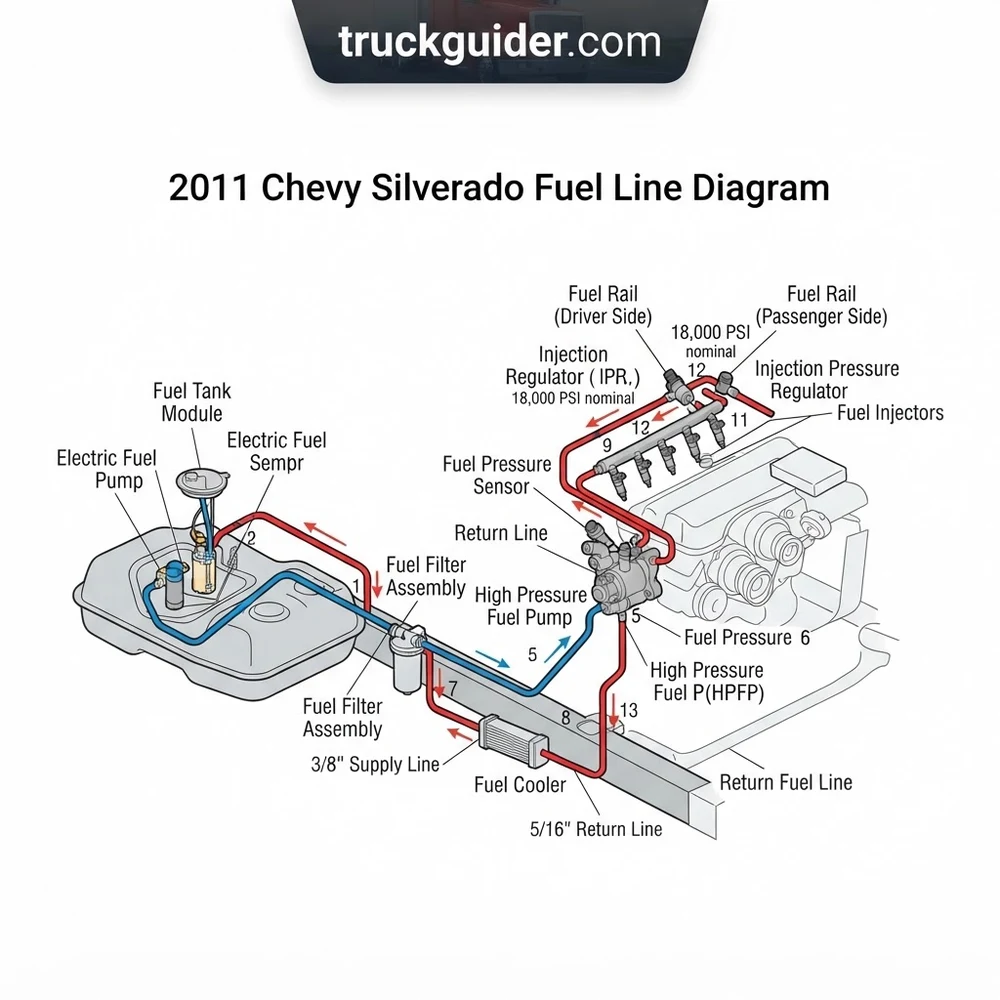
Deconstructing the 2011 Chevy Silverado fuel line diagram requires tracing the hydraulic circuit from the fuel storage cell to the engine compartment manifold. Each component performs a distinct function in maintaining steady line pressure, managing vapor expansion, and preventing cavitation.


As shown in the schematic, the fuel delivery pathway operates as an integrated closed circuit governed by mechanical seals, internal check valves, and electronic pump control modules.
Fuel Pump and Sender Module


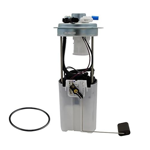
Mounted inside the polyethene fuel tank via a cammed metal retaining lock ring, the fuel pump and sender module houses a high-flow turbine pump, internal 50-micron inlet strainer, fuel level float sensor, and a calibrated reservoir bucket. On gasoline GMT900 applications, the module houses an internal mechanical pressure regulator calibrated to maintain 58 to 62 PSI (400 to 427 kPa). Electrical input is supplied through a 4-pin weather-pack connector: Pin A (Grey wire) provides pulse-width-modulated (PWM) +12V power from the Fuel Pump Flow Control Module (FPCM), Pin B (Black wire) provides direct chassis ground, Pin C (Purple wire) carries the fuel level potentiometer signal to the Body Control Module (BCM), and Pin D (Black/White wire) provides low-reference ground. The top hat of the module features two quick-disconnect steel male spigots: a 3/8-inch outer diameter (OD) supply port and a 5/16-inch OD EVAP purge port.
High-Pressure Fuel Feed Line
The main high-pressure fuel feed line spans the distance between the tank module and the engine firewall. On factory installations, this line consists of a multi-layer fluoropolymer-lined nylon core wrapped in an abrasion-resistant outer jacket, transitioning to rigid coated steel tubing along exposed segments of the driver-side chassis rail. It measures 3/8-inch OD, terminating in SAE J2044 standard quick-connect fittings. This line is rated for a continuous operating pressure of 100 PSI with a burst rating exceeding 250 PSI, accommodating dynamic fuel spikes caused by rapid throttle closures and pressure-wave harmonics inside the rail.
Fuel Rail Assembly
Located in the intake manifold valley beneath the cosmetic engine cover, the fuel rail assembly distributes pressurized fuel directly to the eight EV6 or EV14 fuel injectors. The tubular stainless-steel rail features an integrated balance crossover tube that equalizes fluid mass between the bank 1 and bank 2 rails. On the forward end of the bank 2 (passenger-side) rail sits a fuel pressure test port (standard 7/16-20 UNF Schrader valve). This port serves as the primary mechanical tie-in point for connecting diagnostic fuel pressure gauges and system flushing equipment. Fuel injectors seal into the rail via fluorocarbon Viton upper O-rings (7.8mm ID x 1.9mm cross-section), secured by stamped-steel retaining clips.


EVAP Vapor Purge Line


Running parallel to the primary feed circuit, the 5/16-inch OD evaporative emissions (EVAP) vapor line channels hydrocarbon vapors from the fuel tank vapor dome to the EVAP purge solenoid mounted on the intake manifold. This line bridges the fuel tank roll-over valves, the chassis-mounted charcoal canister, and the engine vacuum port. A specialized service port with a green knurled cap contains an internal Schrader valve (reverse-threaded core) designed specifically for diagnostic nitrogen/smoke machine leak testing down to a threshold of 0.020 inches.
Diesel-Specific Additions: HPFP, Primer Pump, and Fuel Cooler
On 2011 Silverado models equipped with the 6.6L Duramax LML, the plumbing diverges significantly from the gas schematic. The chassis contains no in-tank electric pump; instead, a camshaft-driven Bosch CP4.2 high pressure fuel pump (HPFP) draws fuel via suction directly from the tank. The diesel circuit incorporates an under-hood fuel bowl housing with an integrated manual primer pump and a 12-volt fuel heater to prevent paraffin wax drop-out in cold climates. High-pressure delivery lines from the HPFP to the common rails run at pressures exceeding 29,000 PSI (2,000 bar), regulated by an injection pressure regulator (inlet metering valve / MPROP). Furthermore, diesel configurations include a dedicated fuel return line that routes unburned injector leakage and pump bypass volume back to the tank through a finned, aluminum under-body fuel cooler mounted to the inside of the frame rail.
The 2011 Vortec V8 platform utilizes a true returnless architecture. Fuel pressure is not adjusted via a vacuum-referenced mechanical regulator on the rail; instead, the FPCM (located near the spare tire crossmember) reads line pressure data and modulates pump duty cycles to maintain an exact target pressure across varying engine loads.
2011 Silverado Fuel Line Routing: Feed vs Fuel Return Line Layout


Tracing the fuel lines along the 2011 Silverado chassis requires understanding how General Motors isolated hydraulic circuits across the GMT900 platform. The routing path isolates the fuel charge from the exhaust system while protecting the lines from suspension articulation and road debris.


The fuel bundle originates at the top-forward face of the fuel tank. Lines route forward along the inboard channel of the boxed, hydroformed driver-side frame rail. Specialized triple-slot snap-in plastic retainers secure the lines every 18 to 24 inches to eliminate harmonic vibration. At the transmission crossmember, the bundle steps over the top flange of the frame to bypass the front cab mounts.
| Line Circuit | Outer Diameter & Material | Operating Pressure | Connection Type / Termination |
|---|---|---|---|
| Gasoline Main Feed | 3/8″ (9.52mm) Nylon / Coated Steel | 58–62 PSI (400–427 kPa) | SAE J2044 Quick-Disconnect (Plastic Retainer) |
| Gasoline EVAP Purge | 5/16″ (7.94mm) Nylon Monolayer | -1.5 to +2.5 PSI (Vacuum/Vapor) | SAE Quick-Connect to Charcoal Canister & Manifold |
| Duramax LML Feed (Suction) | 1/2″ (12.7mm) Steel / Reinforced Braided | -3 to -5 in-Hg (Suction Vacuum) | Bite-Type Flare / Push-Lock Quick-Disconnect |
| Duramax LML Fuel Return Line | 3/8″ (9.52mm) Steel / High-Temp Elastomer | 15–45 PSI (Backpressure / Return) | Quick-Connect via Rail Return & Frame Fuel Cooler |
| Diesel HPCR Rail Delivery | 8mm Thick-Wall Seamless Steel | 4,500–29,000 PSI (310–2,000 bar) | Threaded M14x1.5 Compression Flare Nuts |
Near the steering shaft intermediate coupling, the rigid underbody steel lines transition into flexible braided jumper hoses. These braided flex lines accommodate the engine’s rotational torque and powertrain vibration on its hydraulic mounts. On gasoline configurations, the single 3/8-inch braided line runs up the transmission bellhousing and clips onto the rear of the driver-side fuel rail.
Conversely, older GMT800 trucks (1999–2003) routed a secondary continuous fuel return line from a mechanical rail-mounted regulator back to the tank. The 2011 GMT900 gasoline architecture eliminates this return loop entirely. Fuel that reaches the rail must be consumed by the combustion chamber. Excess fuel bypassed by the in-tank module dumps immediately inside the fuel sender bucket, drastically reducing volatile organic compound (VOC) vapor generation by preventing engine heat transfer to the fuel reservoir.
For Duramax LML platforms, the fuel return line remains mandatory. The return loop routes hot diesel fuel from the injector spill-ports and HPFP case-drain down the firewall, into an extruded aluminum fuel cooler fixed to the intermediate frame member, and finally back into the tank module. This thermal step-down prevents return fuel from boiling under low-tank, high-load towing conditions.


Fuel rail pressure on gasoline engines must hold a static 58 to 62 PSI at Key-On-Engine-Off (KOEO). Maximum allowable pressure bleed-down after 10 minutes of pump shutdown is 5 PSI. Rapid drops below 45 PSI point to an in-tank check valve failure, cracked flexible supply jumpers, or a leaking fuel injector nozzle.
Failure Points on the 2011 Chevy Silverado Fuel Line Diagram


The 2011 Silverado fuel plumbing experiences localized structural failures due to environmental oxidation, mechanical fatigue, and material breakdown. Knowing where these failures occur on the line diagram shortens diagnostic time.
The most severe failure point across the GMT900 chassis occurs where the steel line transitions over the driver-side rear frame kick-up, immediately above the front edge of the fuel tank. Road spray, salt brine, and soil become trapped between the frame rail channel and the polyethylene tank shell. This moisture accumulation corrodes the steel supply line directly beneath the protective plastic clips. Because the area is shielded from visual inspection, leaks often develop into pinhole sprays before the driver notices an operational fault.
A second vulnerability lies at the Fuel Pump and Sender Module stamped-steel top hat. The brazed joints connecting the 3/8-inch supply spigot to the top plate undergo heavy galvanic corrosion. Rust blooms expand around the base of the outlet port, compromising the brazed seam. When the seam pinholes, the pump aerates the fuel under pressure, or dumps high-pressure fuel across the top of the tank, creating a fire hazard.
Quick-disconnect fittings represent another common hydraulic failure point. The internal sealing arrangement relies on dual internal Viton O-rings separated by a plastic spacer sleeve, held in place by an internal metal or plastic retainer collar. Over extended operational cycles, the internal Viton seals harden, dry out, and crack due to engine heat-soak and ethanol-blended fuels (E10/E85). Typical symptoms of deteriorated quick-connect fittings include:
- Hard starting and extended cranking times caused by bleed-down of residual fuel rail pressure after shutdown.
- Diagnostic Trouble Code (DTC) P0087 set on diesel models due to air ingress along the suction-side disconnects before the primer pump.
- Lean misfire diagnostic codes (P0171 and P0174) triggered under heavy load when fuel supply volume falls below injector pulse-width demand.
- Pervasive raw gasoline or diesel odors near the cab-to-bed transition seams without wet spots visible on ground pavement.
- Persistent EVAP system leak codes (P0442 minor leak, P0455 gross leak) caused by cracks in the brittle 5/16-inch vapor line quick-connect retaining ring tabs.
Additionally, examine the flexible braided jumper hoses running from the chassis line to the fuel rail. These hoses can develop micro-cracks inside the inner fluoroelastomer lining. While the outer stainless or aramid braid remains intact, high pressure forces atomized fuel through the weave, generating an intermittent mist that is difficult to pinpoint because it evaporates instantly against hot cylinder heads.
Pressurized gasoline atomization poses an immediate fire risk. Never inspect fuel line junctions with the engine running or the ignition energized if fuel odors are present. Never use metallic probes or open incandescent work lights near the fuel tank sending unit top hat.
Replacing Corroded Fuel Lines and Quick-Disconnect Fittings


Replacing rusted OEM rigid fuel lines on a 2011 Silverado requires proper depressurization, disconnection of retaining fittings, and routing of modern replacement lines. Following a structured procedure ensures a sealed, reliable repair.
- Relieve Hydraulic Fuel Pressure: Disconnect the negative terminal of the 12-volt battery using a 10mm wrench. Remove the under-hood fuse block cover. Locate and extract the Fuel Pump Relay (KR75, marked “F/PUMP” in the fuse lid map) or remove the 20A Fuel Pump Fuse (Fuse 21). Reconnect the battery ground, crank the engine for 5 to 7 seconds until it stalls, and then crank for an additional 3 seconds to clear residual line pressure. Re-disconnect the negative battery terminal. Alternatively, thread a fuel pressure gauge with a bleed line onto the fuel pressure test port (Schrader valve) on the engine rail, routing the bleed tube into an approved container.
- Disconnect Quick-Disconnect Collars: Clean away grit, rust, and road grime from the exterior of all quick-disconnect fittings using compressed air and electrical cleaner. Do not skip this cleaning step; sand particles will bind the release collar teeth. Determine the connector type:
For external plastic retaining tabs, lift the secondary safety clip backward and squeeze the release ears inward while pulling the female coupling straight off the steel male tube.
For internal spring-clip connectors, slide an aluminum SAE quick-disconnect tool (3/8-inch blue tool for the feed line; 5/16-inch gray tool for the vapor line) over the metal tube, push the collar tool deep into the connector mouth to splay the garter spring fingers, and pull the female union free. Inspect the male bead profile for pitting; deeply pitted steel spigots cannot reliably seal with new O-rings.
- Gain Access to Tank Module Connections: The top hat of the fuel pump and sender module sits trapped between the top of the tank and the underside of the truck bed floor. You have two access paths: drop the tank or unbolt the truck bed. For shop operations with a lift, support the tank using a transmission jack, remove the two 15mm tank strap bolts (torque spec: 30 lb-ft / 41 Nm), disconnect the filler neck clamp, drop the tank down 6 inches, and disconnect the lines. For driveway repairs, unbolting the eight 18mm truck bed bolts (torque spec: 63 lb-ft / 85 Nm), disconnecting the tail lamp harness, and tilting the driver side of the truck bed upward on wood blocks provides clean access to the fuel pump module without disturbing rusty tank strap bolts.
- Route Replacement Line Kits: Avoid attempting to bend rigid OEM-style steel lines around the chassis while the cab is on the frame. Instead, install pre-bent nylon or CNC-bent multi-piece flexible stainless steel replacement line kits (such as Dorman 819-814 or braided stainless braided AN-to-quick-connect conversions). Snap the replacement lines into the OEM chassis retaining clips, taking care not to twist, kink, or pinch the nylon lines against sharp frame corners. Maintain a minimum 3-inch air gap between flexible nylon fuel lines and vehicle exhaust pipes or catalytic converters.
- Verify Connections, Prime, and Inspect: Push every replacement quick-disconnect fitting firmly onto its corresponding spigot until you hear and feel a distinct mechanical click. Once seated, perform a pull test: grasp the line and pull backward with roughly 20-30 lbs of axial force to confirm the internal locking fingers are seated behind the tube bead. Reinstall the fuel pump relay/fuse and reconnect the negative battery cable. Turn the ignition key to the ON position (KOEO) for 3 seconds, then turn it OFF for 5 seconds; repeat this cycle three times to pressurize the system. Check all line connections, Schrader test ports, and sending unit interfaces for dampness or fluid drips before starting the engine.
| Fastener / Interface | Tool Size | Torque / Metric Spec |
|---|---|---|
| Fuel Tank Support Straps | 15mm Socket | 30 lb-ft (41 Nm) |
| Truck Bed Mounting Bolts | 18mm Socket | 63 lb-ft (85 Nm) |
| Fuel Pump Lock Ring (Cam Type) | J-45722 Spanner / Brass Drift | Fully rotated to mechanical lock stops |
| Duramax HPCR Rail Compression Nuts | 17mm Flare Nut Wrench | 30 lb-ft (41 Nm) |
| Schrader Valve Service Port Core | Standard Core Driver Tool | 3 to 5 lb-in (0.34 to 0.56 Nm) |
2011 Chevy Silverado Fuel Line Diagram Diagnostics and FAQs
What size quick-disconnect tools are required for the 2011 Chevy Silverado fuel lines?
To disconnect all fuel and emissions plumbing on a 2011 Silverado, you need two standard SAE disconnect tools: a 3/8-inch tool for the primary fuel supply line (engine compartment and tank module) and a 5/16-inch tool for the EVAP vapor purge line and diesel return connections. Metal disconnect tools (anodized aluminum or spring-steel scissor style) are recommended over plastic variants; road debris often packs into the connector cavities on GMT900 trucks, requiring extra leverage to depress the retaining collar fingers.
What is the correct factory fuel pressure for a 2011 Silverado 5.3L Vortec?
According to factory GM engineering specifications, the 2011 5.3L Vortec fuel delivery system must maintain between 58 and 62 PSI (400 to 427 kPa) static pressure with the ignition key turned ON and the engine off (KOEO). When the engine idles, the Fuel Pump Flow Control Module dynamically adjusts pump pulse-width modulation, but pressure must never dip below 55 PSI under wide-open-throttle (WOT) high-load testing. Any pressure reading under 50 PSI indicates an obstructed fuel sock, failing pump motor windings, or an internal leak in the tank module flexible line.
Can you replace rusted steel fuel lines with flexible nylon fuel lines?


Yes. Flexible multi-layer nylon line kits engineered specifically for the GMT900 chassis are a standard, DOT-compliant repair solution. Nylon tubing resists road salt, galvanic corrosion, and ethanol blends. When installing nylon lines, use pre-formed kits that feature factory-style SAE J2044 quick-connect ends pressed into the nylon via hydraulic clamping tools. Never secure high-pressure fuel lines using screw-type worm gear hose clamps over barbed fittings; smooth-bore high-pressure fuel lines require calibrated 360-degree crimp clamps or push-on thermo-formed quick-disconnect junctions to prevent high-pressure blow-offs.
How do you bleed air from the fuel lines on a 2011 Duramax LML diesel?
Unlike gasoline trucks that automatically purge air through the injectors via continuous electric pressure, the 2011 Duramax 6.6L LML requires manual priming if lines are uncoupled. Locate the cast-aluminum primer pump head assembly on the passenger side of the engine bay, above the fuel filter. Loosen the plastic or brass air-bleed vent screw 2 to 3 turns using a flathead screwdriver. Depress the large circular primer button repeatedly until clean, bubble-free diesel fuel flows out of the bleeder port. Tighten the air-bleed screw (do not over-tighten, max torque 18 lb-in), then pump the primer button an additional 10 to 15 times until it becomes firm to the touch. The vehicle is then ready to start.
Why are there three hard lines exiting the fuel tank area on some 2011 Silverado configurations?
On gasoline GMT900 models, you will trace three primary lines along the frame channel: the 3/8-inch primary fuel feed line, the 5/16-inch EVAP purge line (routing to the engine intake manifold), and the larger 5/8-inch EVAP vent canister line (routing to the fresh-air vent solenoid and remote filter box mounted above the spare tire). On diesel models, the three lines consist of the primary high-volume suction feed line, the low-pressure fuel return line running through the fuel cooler, and the fuel tank vent line.
Step-by-Step Guide to Understanding the 2011 Chevy Silverado Fuel Line Diagram
Identify – Locate the fuel pump relay in the under-hood fuse block and pull it to relieve system pressure.
Locate – Identify the nylon fuel lines connected to the top of the fuel tank or the engine-side fuel rail.
Reference – Use the 2011 Chevy Silverado fuel line diagram to confirm the routing of the supply and return lines.
Connect/Route – Secure all quick-connect fittings until they click, ensuring the plastic safety clips are fully engaged.
Verify – Reinstall the fuel pump relay, turn the ignition to ‘ON’ without cranking, and check for leaks at every connection.
Troubleshoot – If the engine stumbles, re-verify the fuel pressure at the rail and inspect for pinched lines or air pockets in the fuel bowl.