2011 Chevy Silverado Radio Wiring Diagram: 2026 Pinout Guide

On the 2011 Chevy Silverado 14-pin primary radio connector (X1), pin 1 (Red/White) serves as the constant 12V hot wire, while pin 8 (Black/White) is the main ground wire. Switched accessory power is governed through pin 14 (Dark Green) via GM-LAN data, requiring an aftermarket interface module rather than a direct ignition connection.
📌 Key Takeaways
- Pin 1 (Red/White, 18 AWG) provides uninterrupted +12V battery power protected by the 15A RADIO fuse.
- Unlike residential AC setups, vehicle 12V systems use direct chassis grounding; never mistake speaker negative returns for a common neutral wire.
- Switched +12V accessory power relies on GM-LAN digital communication; an integration interface module is required to maintain Retained Accessory Power (RAP).
- Tapping the Dark Green wire (pin 14) for manual 12V switching corrupts the vehicle high-speed data network and trips BCM diagnostic trouble codes.
- Standard stereo replacement is DIY-friendly with a pre-wired harness, but premium Bose amplified systems require interface modules or pro installation.
Modernizing or troubleshooting the audio system in a GMT900 platform truck requires a comprehensive understanding of the 2011 Chevy Silverado radio wiring diagram. Unlike older vehicles that relied on standard analog switching circuits, General Motors engineered the 2011 Silverado with an integrated serial data network where the head unit acts as both an entertainment center and an audible output for vital vehicle systems. Whether you are replacing a failed stock head unit, integrating an aftermarket navigation deck, or resolving parasitic battery drain issues, tracing every hot wire, ground wire, and data lead with factory-grade precision is necessary to maintain system stability and prevent diagnostic trouble codes within the vehicle control modules.
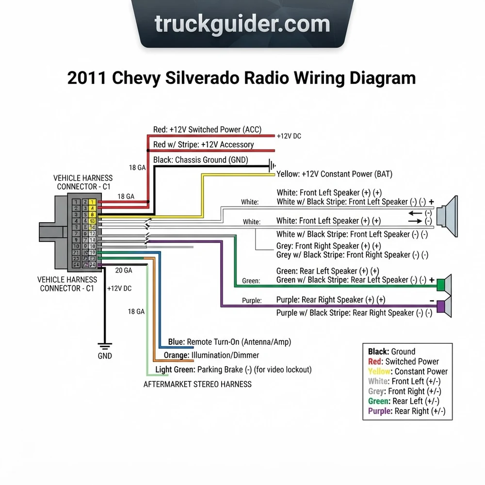
2011 Chevy Silverado Radio Wiring Architecture: Base vs. Bose Systems


The electrical backbone of the 2011 Chevrolet Silverado audio configuration is built upon GM’s GMT900 full-size truck architecture. Central to this platform is the total departure from conventional analog switched +12V accessory wiring behind the dashboard. Instead, the factory radio relies on an unswitched constant battery feed paired with low-speed serial communication commands delivered over the GMLAN single-wire data bus network. In this network environment, the radio receives wake-up commands, vehicle speed signals (VSS) for speed-compensated volume, steering wheel control protocols, and illumination dimming data directly from the Body Control Module (BCM). You can review our detailed breakdown of the Silverado BCM wiring diagram to understand how serial communication packets are routed across the cab.



The factory radio harness does not contain a switched +12V accessory lead (traditional red wire). Terminal pin 13 carries a continuous 33.33 kbps GMLAN data stream that toggles the internal radio circuitry between active and sleep modes. Splicing into this wire with standard 12V test probes will corrupt data bus traffic and trigger communication DTCs.
Non-Bose Base Audio System (RPO UQ3 and UQ5)


The standard, non-amplified factory audio layout is identified by Regular Production Option (RPO) codes UQ3 or UQ5 on the glovebox service parts identification sticker. In this standard setup, the factory head unit houses an internal multi-channel Class-AB amplifier. High-level speaker output leads run directly from the rear terminal blocks of the head unit harness to the cab speakers:
- Front Stage: 6.5-inch door woofers wired in parallel with 1-inch dashboard tweeters featuring inline passive crossover capacitors. Nominal system load is 4 ohms per channel.
- Rear Stage: 6.5-inch full-range door speakers (Extended and Crew Cab) or 4×6-inch pillar speakers (Regular Cab) driven directly at 4 ohms.
Bose Premium Audio System (RPO UQA) Signal Path
Silverado models equipped with the factory Bose sound package (RPO UQA) employ a fundamentally different architecture. The factory head unit no longer outputs high-level amplified audio. Instead, it generates low-level, variable, balanced-differential analog audio signals. These pre-amplified channels exit the radio terminal block through shielded twisted-pair wiring and travel downstream to an external Bose Class-D digital signal processing amplifier located underneath the center floor console (or on the rear cab wall in select cab variants).
The Bose amplifier decodes these differential signals, processes phase and time alignment, and outputs dedicated high-current audio to individual discrete channels: front dashboard 3.5-inch mid-high drivers, front 6.5-inch low-frequency door woofers (typically rated at a low 1.9 to 2.0 ohms impedance), rear door speakers, and a center-console mounted 5.25-inch neodymium subwoofer powered via dual voice coils. A dedicated 12V low-current remote trigger wire alerts the Bose amplifier to power on when the GMLAN network signals radio initialization.
Non-Bose base systems operate at a standard 4-ohm speaker impedance with head unit outputs delivering approximately 14-18W RMS per channel. Bose (UQA) systems utilize 2-ohm high-efficiency woofers driven by an external DSP amplifier. Connecting aftermarket head units directly to Bose factory speakers without the amplifier will overcurrent standard deck amplification.
2011 Chevy Silverado Radio Wiring Diagram and Pin Assignment Table


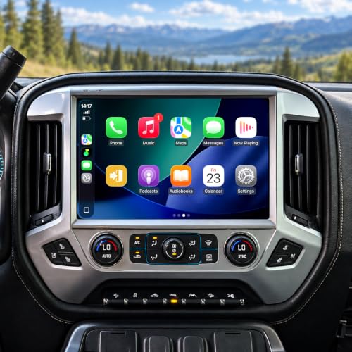
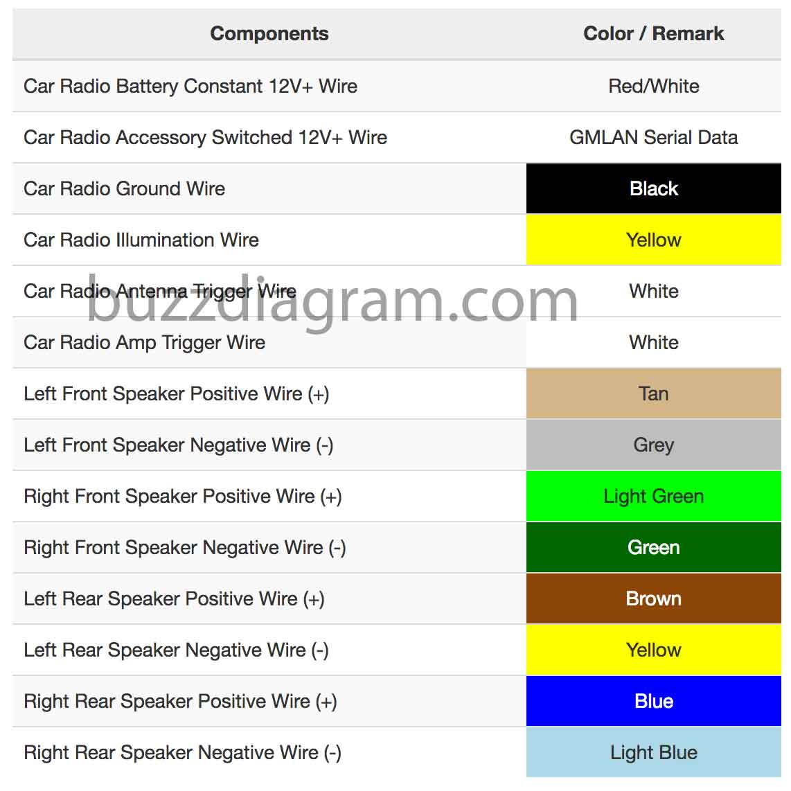
The 2011 Chevrolet Silverado radio interface utilizes two primary Delphi/Aptiv connectors: the Primary 14-Pin Connector (Connector X1 / C1) and the Secondary 16-Pin Auxiliary Connector (Connector X2 / C2). Understanding the exact pin assignment, circuit identifier, wire color code, wire gauge, and functional voltage ranges is mandatory before stripping wires or splicing harnesses.


The primary connector houses the critical operating circuits: the high-current unswitched hot wire originating from the 15A RADIO fuse in the underhood fuse block, the primary ground wire terminating at the instrument panel chassis ground, the GMLAN serial data link, and the front speaker output channels. The secondary connector carries the rear audio channels, auxiliary signals, backup camera inputs (if factory equipped), steering wheel controls, and downstream communication leads.
Primary Connector X1 (14-Pin) Pin Assignment and Circuit Descriptions
| Pin # | Wire Color Code | Circuit Function | Wire Gauge | Operating Voltage / Signal Type |
|---|---|---|---|---|
| 1 | Red / White | Constant Battery Power (+12V Hot Wire) | 18 AWG | +12.0V to +14.4V DC Constant |
| 2 | Tan | Left Front Speaker Positive (+) [Base] / Low-Level Preamp (+) [Bose] | 20 AWG | Analog Audio AC Signal (High/Low) |
| 3 | Gray | Left Front Speaker Negative (-) [Base] / Low-Level Preamp (-) [Bose] | 20 AWG | Analog Audio AC Inverted Signal |
| 4 | Light Green | Right Front Speaker Positive (+) [Base] / Low-Level Preamp (+) [Bose] | 20 AWG | Analog Audio AC Signal (High/Low) |
| 5 | Dark Green | Right Front Speaker Negative (-) [Base] / Low-Level Preamp (-) [Bose] | 20 AWG | Analog Audio AC Inverted Signal |
| 6 | Bare / Drain | Audio Shield Ground (Bose Models Only) | 22 AWG | 0V DC Chassis Reference |
| 7 | Empty / Not Used | Reserved | — | — |
| 8 | Black | Primary Chassis Ground Wire | 18 AWG | 0V Ground Potential (< 0.2 Ohm to Ground) |
| 9 | White | Amplifier Remote Turn-On Control (Bose UQA) | 20 AWG | +12.0V DC Active High Trigger |
| 10-12 | Empty / Not Used | Reserved | — | — |
| 13 | Dark Green | GMLAN Low-Speed Serial Data Bus | 20 AWG | 0V to 5V Square Wave Serial Data |
| 14 | Empty / Not Used | Reserved | — | — |
Secondary Connector X2 (16-Pin) Pin Assignment and Circuit Descriptions


| Pin # | Wire Color Code | Circuit Function | Wire Gauge | Operating Voltage / Signal Type |
|---|---|---|---|---|
| 1 | Dark Blue / White | Left Rear Speaker Positive (+) [Base/Bose] | 20 AWG | Analog Audio AC Signal |
| 2 | Dark Blue | Left Rear Speaker Negative (-) [Base/Bose] | 20 AWG | Analog Audio AC Inverted Signal |
| 3 | Brown | Right Rear Speaker Positive (+) [Base/Bose] | 20 AWG | Analog Audio AC Signal |
| 4 | Yellow | Right Rear Speaker Negative (-) [Base/Bose] | 20 AWG | Analog Audio AC Inverted Signal |
| 5-8 | Various / Bare | Auxiliary Input Signals / Drain Wire | 22 AWG | Low-Level Line Input (Left, Right, Common) |
| 9 | Dark Blue | Steering Wheel Controls Signal (Key 1 / Variable Voltage) | 20 AWG | Variable Resistive Voltage Ladder (0V to 5V) |
| 10 | White / Black | Steering Wheel Controls Reference Return | 20 AWG | Sensor Ground Reference |
| 11-16 | Various | Rear Seat Entertainment (RSE) / Camera Leads | 20-22 AWG | NTSC Composite Video / Data Feeds |
When measuring circuits at the factory terminal block, the speaker negative returns should never be conflated with the vehicle chassis ground wire or an AC neutral wire. In both base and Bose systems, speaker return leads are active, balanced-differential outputs biased to approximately one-half of the rail voltage (roughly 6.0V DC to ground when the system is operating). Grounding any speaker return lead directly to the steel chassis will short out the internal output stage of the head unit or the Bose amplifier.
Connecting an Aftermarket Head Unit Using the 2011 Silverado Terminal Block Harness


Installing an aftermarket head unit into a 2011 Chevy Silverado cannot be accomplished with a basic universal splice harness. Because the factory harness lacks a switched accessory circuit, you must incorporate a CAN-Bus / GMLAN data interface module (such as the PAC RP5-GM31, Crux SWRGM-49, or Axxess GMOS-LAN-012) to accurately decode network traffic and re


Do not probe the instrument panel wiring or ignition switch harness looking for an accessory hot wire. Tapping into unfamiliar circuits can backfeed the Supplemental Restraint System (SRS) or interfere with the Silverado trailer brake controller wiring network, generating ABS and StabiliTrak failure codes.
-
Disconnect Battery and Verify Static Potential: Disconnect the negative battery terminal clamp using a 10mm socket. Isolate the cable terminal. Wait ten minutes to allow the SRS backup power capacitors to discharge fully. Use a digital multimeter (DMM) to confirm that the battery terminal block voltage measures 0.0V across all circuits prior to removing trim pieces.
-
Disassemble the Center Instrument Cluster Bezel: Gently pry outward on the perimeter of the textured center dash bezel using a non-marring nylon pry tool. Release the retaining clips working from the bottom upward. Disconnect the passenger airbag status light and HVAC climate control wiring harnesses. Remove the four 7mm hex-head screws securing the factory radio chassis and slide the radio out of the dash cavity.
-
Integrate the GMLAN Interface Adapter: Connect your aftermarket radio’s wiring pigtail to the GMLAN interface module harness using crimped heat-shrink butt connectors or soldered terminal block junctions. Match the standard EIA color codes from the aftermarket deck to the interface adapter inputs:
- Yellow (Battery Constant Hot Wire): Connects to Pin 1 (Red/White) through the adapter harness.
- Black (Ground Wire): Connects to Pin 8 (Black) ground terminal block.
- Red (Switched Accessory Feed): Connects to the red switched output wire emerging directly from the interface module’s microprocessor (which translates GMLAN data into a clean +12V DC ACC trigger).
- Orange/White (Illumination): Connects to the interface illumination lead to provide stepped voltage drops when parking lamps activate.
-
Configure Audio Routing (Base vs. Bose Integration):
- For Non-Bose (UQ3/UQ5): Connect the standard white, white/black, gray, gray/black, green, green/black, purple, and purple/black speaker output leads directly from the aftermarket head unit through the interface harness to drive factory 4-ohm speakers directly.
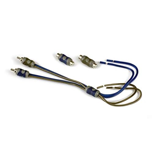
- For Bose (UQA): The aftermarket head unit’s high-level speaker outputs must not be run into the low-level inputs of the Bose amplifier without attenuation. Connect the low-level RCA pre-amp outputs (Front Left/Right, Rear Left/Right) from your aftermarket deck directly into the RCA input leads on the interface harness. If using a head unit lacking RCA pre-outs, you must install an adjustable 4-channel Line Output Converter (LOC) to step speaker-level voltages down to line-level (1.0V to 2.0V RMS).
- Amp Trigger: Splice the aftermarket radio’s Blue/White remote turn-on output wire directly to the remote turn-on wire going to Pin 9 (White) on Connector X1 to trigger the Bose amplifier into operational status.
-
Install Antenna Adapter and Retain Factory Chimes: Connect a GM antenna adapter (such as a Metra 40-CR10) to the proprietary factory micro-coaxial antenna connector. Connect your steering wheel control (SWC) 3.5mm jack or key input lead to the interface module port. Verify the dip-switch settings on your interface module match the head unit manufacturer brand to ensure steering wheel control resistance signals are properly translated.
-
Perform Circuit Verification and Reassembly: Before snapping dash bezels into place, temporarily reconnect the truck’s negative battery terminal. Turn the ignition key to the RUN position and confirm: head unit boot-up, chime playback volume through the driver door speaker, steering wheel control button map assignments, and clear audio output across all channels without clipping or background engine whine. Once verified, secure the unit with the four 7mm bolts and snap the trim bezel firmly back into the dash frame.
Diagnosing 2011 Silverado Stereo Wiring Mistakes and Electrical Troubleshooting


Due to the complex relationship between the audio system and GM’s serial network, wiring errors on the 2011 Silverado can trigger diverse symptoms ranging from dead batteries to lost system chimes. The following systematic diagnostic steps target the most frequent electrical installation failures:
-
Aftermarket Radio Fails to Power Down (Retained Accessory Power Malfunction):
If the aftermarket stereo stays powered on indefinitely after turning off the ignition key and opening the driver’s door, the GMLAN data interface adapter is not interpreting the door status circuit. The BCM monitors the driver’s door ajar switch via a dedicated signal line and transmits the “Door Open / Terminate RAP” message over the low-speed data line. Check for faulty door jamb switches, or inspect terminal Pin 13 (Dark Green) on the primary radio connector. If an installer spliced an analog accessory wire directly into a continuous hot wire fuse, the radio will remain on 100% of the time, resulting in severe parasitic battery drain.
-
Complete Loss of Vehicle Warning Chimes and Turn Signal Audible Clicks:
In the 2011 Silverado, warning chimes (such as headlights-on, key-in-ignition, seatbelt alerts, and turn signal flasher audio) are synthesized digitally inside the BCM, transmitted across the GMLAN serial data bus, and output physically through the front left (driver door) speaker channel. If you bypass the GMLAN interface adapter or install an incorrect harness, the audio system will operate, but all safety chimes will disappear completely. Restoring this functionality requires integrating an aftermarket Chime Retention Module or using an interface adapter featuring an integrated high-frequency onboard piezo speaker.
-
High-Pitched Alternator Whine and Ground Loop Noise:
Alternator whine that varies with engine RPM is generally caused by grounding potential differences between the aftermarket deck and the factory Bose amplifier or vehicle chassis. If you measure more than 0.2 ohms of resistance between the radio harness ground wire (Pin 8, Black) and raw steel behind the dashboard, cut the ground wire splice and install a dedicated 14 AWG to 16 AWG ground wire terminated with a star-washer ring terminal directly to an unpainted chassis structural brace. Furthermore, ensure the factory audio cable shield drain wire (Connector X1, Pin 6) is coupled cleanly to the signal ground rather than left unshielded and floating.
-
Muffled, Hollow Sound or Intermittent Thermal Cutout (Phase Distortion):
A classic installation mistake involves inverting the polarity of speaker output leads (e.g., swapping speaker positive and speaker negative on one side). While an inverted channel will still produce sound, the acoustic waves will cancel each other out, stripping away virtually all low-frequency bass output. Use an audio test file or a 9V battery test (pulsing briefly to observe outward cone travel) to confirm positive speaker polarity. On Bose systems, mismatching preamp output voltage to amplifier input sensitivity will saturate the amplifier input stage, driving it into immediate thermal protection shutdown.
-
Parasitic Battery Draw Overload (Sleep State Failure):
A healthy 2011 Silverado should exhibit a quiescent parasitic battery draw of under 50 milliamps (0.050A) after entering total sleep mode (which takes between 10 to 20 minutes following key-off). If your battery drains overnight after a stereo install, wire an inline ammeter in series with the disconnected negative battery terminal. If the draw remains above 200mA, disconnect the aftermarket radio harness. A malfunctioning GMLAN interface module that fails to release the data bus will keep other modules on the vehicle network awake, preventing the BCM and instrument cluster from reaching sleep mode. Reviewing the GMT900 instrument cluster pinout helps clarify how sleep states are managed across the shared GM communication network.
2011 Chevy Silverado Stereo Wiring and Pinout Frequently Asked Questions
Why is there no switched ignition +12V accessory wire in the 2011 Silverado radio harness?
General Motors phased out analog switched ignition wires at the radio harness on the GMT900 platform to reduce weight and simplify electrical packaging. The factory head unit receives a single, unswitched constant battery hot wire (Pin 1, Red/White) that powers its internal memory and operating circuits continuously. Switched functions like Retained Accessory Power (RAP) and ignition-on are triggered entirely via digital software packets sent across the GMLAN single-wire data bus network (Pin 13, Dark Green). An aftermarket installation requires a specialized data interface module to interpret these packets and synthesize a traditional +12V switched accessory power wire.
Can I install an aftermarket head unit in a Bose-equipped Silverado without replacing the factory amplifier?
Yes, you can retain the factory Bose amplifier and all stock 2-ohm speakers when installing an aftermarket head unit. However, you must use an integration harness equipped with low-level differential RCA inputs rather than running the high-level speaker wire leads directly from your aftermarket stereo into the harness. The Bose amplifier expects balanced, low-voltage preamp signals (approximately 1.0V to 2.0V RMS). Supplying high-level (amplified) speaker outputs from an aftermarket head unit directly into the Bose harness will overdrive the amplifier inputs, causing severe audio distortion, extreme baseline hiss, and amplifier thermal overload.
What wire gauge should I use when repairing or extending the 2011 Silverado radio ground wire?
The OEM primary radio ground circuit (Pin 8, Black) uses an 18 AWG copper lead that grounds to the main instrument panel harness block. When upgrading to an aftermarket head unit—especially higher-power digital multimedia receivers or navigation systems featuring external USB power banks—it is recommended to step up to a 16 AWG or 14 AWG multi-strand automotive-grade copper wire. The ground resistance measured between the radio chassis and bare metal floor or dash substructure should read less than 0.2 ohms to prevent alternator whine and ground loop voltage drops.



How do I know if my 2011 Silverado has the Bose sound system or the base stereo system?


The most definitive method is to inspect the Service Parts Identification label located inside the front passenger glove compartment. Search the alphabetical list of three-digit RPO codes for the code UQA, which denotes the Bose Premium 7-speaker amplified audio package. If your sticker instead lists RPO code UQ3 or UQ5, your truck came equipped with the non-amplified standard factory audio system. Visually, Bose-equipped trucks feature Bose emblems on the front door speaker grilles and house an integrated subwoofer enclosure inside the floor-mounted center console.
What fuse powers the factory radio in a 2011 Chevy Silverado, and where is it located?
The primary constant +12V power to the radio is supplied by the 15-amp mini-fuse labeled RADIO (typically Fuse #41, depending on production split), located in the underhood electrical center on the driver side of the engine compartment. If your Silverado is equipped with the Bose premium sound system (RPO UQA), the external Bose amplifier is protected by an independent 30-amp fuse labeled AMP located in the same underhood fuse block. If the radio has completely lost power, check both the RADIO fuse and the harness terminal block at Pin 1 using a 12V test light or DMM.
Step-by-Step Guide to Understanding the 2011 Chevy Silverado Radio Wiring Diagram
Identify – Disconnect the negative battery terminal using a 10mm wrench to protect delicate GM-LAN modules from electrical shorts.
Locate – Pry off the surrounding instrument panel dash trim bezel and unbolt the factory head unit mounting screws.
Reference – Inspect the factory harness wire color code and pin assignment chart to identify speaker lines, 12V hot wire, and data terminals.
Connect/Route – Splice your replacement stereo harness into a specialized GM data adapter using insulated crimp caps or heat-shrink solder joints.
Verify – Reconnect battery power, then test audio balance, door chime generation, steering wheel controls, and turn-off delay sequence.
Troubleshoot – Check the underhood 15A RADIO fuse and verify solid ground wire continuity with a digital multimeter if no power is received.