2012 Ford F150 Exhaust System Diagram: 2026 Layout Guide

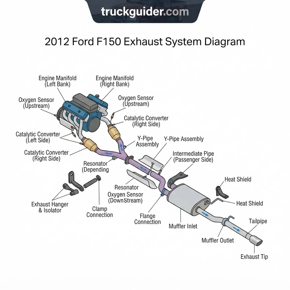
The 2012 Ford F150 exhaust system layout routes from the cylinder head manifolds through dual catalytic converter downpipes into a single 2.5-inch or 3-inch intermediate Y-pipe. It traverses through an inline resonator, enters an offset single-inlet/outlet muffler, and exits via an over-axle tailpipe secured by four rubber isolator hangers.
📌 Key Takeaways
- Exhaust flange nuts at the catalytic converter downpipe require 30 to 35 lb-ft of torque to prevent leaks.
- Upstream wideband O2 sensors thread directly before catalysts; downstream monitoring sensors sit in the intermediate pipes.
- The flex pipe section directly behind the Y-collector is the most frequent point of structural fatigue and rust-through.
- Isolator bracket deterioration causes severe driveline vibration and contact rattles against the rear axle crossmember.
- P0420/P0430 codes often indicate failing catalytic converter cores rather than faulty downstream oxygen sensors.
The 2012 Ford F-150 platform utilizes a modular, multi-stage exhaust routing architecture designed to handle high exhaust gas volumes while meeting stringent Federal Tier 2 Bin 5 and California LEV-II emissions standards. Fabricated primarily from 409-grade stainless steel tubing, the factory exhaust path incorporates isolated cylinder bank scavenging, precise closed-loop stoichiometric fuel feedback, catalytic reduction, acoustic pulse cancellation, and chassis-specific tailpipe routing. Understanding the mechanical layout, connection flanges, mounting isolators, and sensor locations of this assembly is critical for diagnosing performance drops, locating stubborn exhaust leaks, replacing blown manifold hardware, or performing cat-back upgrades across various wheelbase configurations.
2012 Ford F150 Exhaust System Diagram: Component Breakdown


Every factory 2012 F-150 exhaust assembly consists of seven primary mechanical stages between the cylinder head exhaust ports and the atmosphere. Understanding the structural progression of these components ensures accurate diagnosis of backpressure anomalies, physical clearance issues, and thermal stress points along the driveline.


| Component | OEM Base Part | Material & Dimensions | Torque & Mounting Spec |
|---|---|---|---|
| Exhaust Manifolds / Turbo Outlets | 9430 (RH) / 9431 (LH) | Cast Ductile Iron or Tubular 409 SS | M8x1.25 Studs: 18–20 lb-ft (24–27 Nm) |
| Upstream Heated O2 Sensors (HEGO/UEGO) | 9F472 / 9G444 | Thread: M18x1.5, 22mm Hex | 35 lb-ft (47 Nm) into downpipe bung |
| Catalytic Converter Downpipe Assembly | 5E212 (RH) / 5E213 (LH) | Dual 2.5-inch OD 409 Stainless Steel | Flange Nuts: 30–35 lb-ft (40–48 Nm) |
| Y-Pipe Collector / Merge Section | 5246 | Dual 2.5-inch inlet to Single 3.0-inch outlet | Two-bolt ball-and-socket flare connection |
| Intermediate Resonator Assembly | 5212 | 3.0-inch OD, 16-gauge tubing | Torca Torx Band Clamp: 35 lb-ft (48 Nm) |
| Main Absorption Muffler | 5230 | Triple-chamber 409 SS, 3.0-inch in/out | Welded bracket to EPDM rubber hangers |
| Over-Axle Tailpipe & Tip | 5255 | 3.0-inch Mandrel-Bent Tubing | Slip-fit flange clamp: 35 lb-ft (48 Nm) |
The primary scavenging phase begins at the cylinder head interface. Factory exhaust manifolds route high-temperature gas through individual runners into a collector outlet. The downpipe assembly immediately integrates catalytic wash-coat substrates with upstream wideband air-fuel sensors positioned in the neck of each collector. Gas continues through dual direct-fit pipes into a single Y-pipe assembly, transitioning two 2.5-inch runners into a consolidated 3.0-inch single intermediate stream.
Downstream of the Y-pipe collector, the exhaust passes through the intermediate resonator assembly. This straight-through perforated core resonator cancels harmonic resonance in the 1,800 to 2,200 RPM cruising range. From the resonator, gas enters the large-case, triple-chambered muffler featuring internal baffles and sound-dampening fiberglass matting. Cleaned, dampened gases are evacuated through the over-axle tailpipe assembly, which rises over the passenger rear axle housing and terminates behind the passenger rear tire.
Factory torque sequences for the cylinder head exhaust studs must be strictly observed: install studs finger-tight, fit the multi-layer steel (MLS) gasket, hand-thread all prevailing-torque nuts, then execute a center-out cross-pattern torque sequence in two stages: Stage 1 at 89 lb-in (10 Nm), and Stage 2 at 18 lb-ft (25 Nm) on cast iron; 20 lb-ft (27 Nm) on aluminum heads.
Powertrain Variations in the 2012 F-150 Exhaust Schematic




While the center muffler and over-axle tailpipe remain largely uniform across configurations, the front half of the exhaust blueprint varies substantially based on engine architecture. The four powertrain options available for the 2012 model year—the 3.5L EcoBoost V6, 5.0L Coyote V8, 3.7L Cyclone V6, and 6.2L Boss V8—demand completely different header designs, catalytic converter placements, and front downpipe routings.
| Powertrain Platform | Manifold / Turbo Layout | Downpipe Collector Size | Catalyst Configuration |
|---|---|---|---|
| 3.5L EcoBoost (Twin-Turbo V6) | Cast iron manifolds feeding dual BorgWarner K03 turbos | Dual 2.5-inch turbine outlet downpipes | Close-coupled brick pair + downpipe bricks |
| 5.0L Coyote (DOHC V8) | Short-tube tubular 409 SS factory headers | Dual 2.5-inch into 3.0-inch ball-flare collector | Dual high-flow close-coupled catalytic bricks |
| 3.7L Cyclone (Ti-VCT V6) | High-silicon ductile cast iron log manifolds | Dual 2.25-inch intermediate merge to 2.5-inch | Dual integrated manifold-converter converters |
| 6.2L Boss (SOHC V8) | Heavy cast nodular iron high-volume manifolds | Dual 2.5-inch heavy-gauge stainless runners | Large-diameter dual underfloor catalyst units |
The 3.5L EcoBoost features a distinct architecture: each cylinder head directly drives an engine-mounted turbocharger. The exhaust schematic bypasses conventional header routing; instead, short cast runners exit directly into the twin turbine housings. The exhaust downpipes attach directly to the turbocharger turbine housings using a two-stud downpipe flange. If servicing these turbo components, refer to the 3.5L EcoBoost turbocharger oil feed line routing to prevent contamination during exhaust flange separation.



In contrast, the 5.0L Coyote uses hydroformed tubular stainless steel short-tube manifolds engineered to optimize exhaust scavenging at higher RPM ranges. The 3.7L Cyclone V6 incorporates compact cast-iron log manifolds designed for fast catalytic warm-up cycles. The heavy-duty 6.2L Boss V8 utilizes oversized cast-iron exhaust manifolds coupled to high-flow downstream converters, utilizing thicker flange rings to handle the higher thermal mass and pulse energy generated by the 411-horsepower engine.
Do not interchange downpipe assemblies between 3.5L EcoBoost and 5.0L Coyote trucks. While the downstream intermediate extension flange patterns match, the engine mating flanges, bank drop angles, and primary oxygen sensor orientations differ. Forcing mismatched downpipes introduces mechanical stress that cracks the turbo discharge housing or strips manifold flange studs.
Wheelbase and Cab Sizing in the 2012 F150 Exhaust Layout


Because the 2012 Ford F-150 platform was sold across five distinct wheelbase configurations, Ford modularized the exhaust layout. Rather than changing the muffler, catalytic converters, or tailpipe for every frame variant, engineers isolated all cab and bed dimensional adjustments exclusively to the intermediate extension pipe located between the Y-pipe collector flange and the front resonator body.
| Cab Style | Bed Length | Wheelbase (Inches) | Intermediate Pipe Configuration |
|---|---|---|---|
| Regular Cab | 6.5-Foot Bed | 126.0 in | Direct Resonator Integration (No Extension) |
| Regular Cab | 8.0-Foot Bed | 144.5 in | 18.5-inch Extension Tubing (Single Hanger) |
| SuperCab (Extended) | 6.5-Foot Bed | 144.5 in | 18.5-inch Extension Tubing (Single Hanger) |
| SuperCab (Extended) | 8.0-Foot Bed | 163.1 in | 37.1-inch Extension Tubing (Dual Frame Hangers) |
| SuperCrew (Crew Cab) | 5.5-Foot Bed | 144.5 in | 18.5-inch Extension Tubing (Single Hanger) |
| SuperCrew (Crew Cab) | 6.5-Foot Bed | 156.8 in | 30.8-inch Extension Tubing (Single Reinforced Hanger) |
When sourcing replacement pipes or an aftermarket system, identify your truck’s wheelbase via the Safety Compliance Certification Label on the driver-side B-pillar (under “WB”). The 144.5-inch chassis is the most prevalent configuration across SuperCab 6.5-ft, SuperCrew 5.5-ft, and Regular Cab 8-ft models. For this wheelbase, the intermediate pipe measures exactly 18.5 inches from flange face to slip-joint seat.


Rubber isolation hangers are tuned according to intermediate pipe weight. The 156.8-inch and 163.1-inch wheelbases incorporate secondary frame bracket crossmembers equipped with 65-durometer vulcanized EPDM rubber isolators. These isolators absorb vertical and torsional driveline movement, isolating the long pipe run from exhaust fatigue cracks.
If installing a cat-back exhaust kit engineered for universal F-150 fitment, manufacturers ship the pipe cut to length for the 163.1-inch wheelbase. You must cut down the intermediate pipe with a cold saw or metal-cutting chop saw using the manufacturer-provided wheelbase cut matrix before assembling downstream joints.
Tracing 2012 Ford F150 Exhaust System Diagram Sensors and Flow




Diagnosing sensor faults and backpressure issues requires tracking exhaust flow sequentially through the structural schematic, from the engine cylinder heads down to the tailpipe discharge.
- Cylinder Port Scavenging and Primary AFR Sensing: Exhaust gas pulses exit the cylinder heads (Bank 1 passenger side, Bank 2 driver side) into the manifolds. Immediately at the manifold collector outlet—or right after the turbocharger turbine housing on 3.5L models—the gas strikes the Upstream Oxygen Sensor (Bank 1 Sensor 1 / Bank 2 Sensor 1). These are wideband Air-Fuel Ratio (UEGO) sensors that produce a continuous variable current signal to the Powertrain Control Module (PCM), maintaining exact 14.7:1 stoichiometric combustion via short-term fuel trim (STFT) adjustments.
- Catalytic Conversion and Efficiency Monitoring: The gas stream enters the ceramic honeycomb substrate of the primary catalytic converters. Platinum, palladium, and rhodium wash-coats oxidize carbon monoxide (CO) and unburned hydrocarbons (HC) into carbon dioxide and water, while reducing oxides of nitrogen (NOx). As gases exit the catalyst brick, they contact the Downstream Heated Oxygen Sensors (Bank 1 Sensor 2 / Bank 2 Sensor 2). These narrowband sensors cycle between 0.1V (lean) and 0.9V (rich), confirming catalyst efficiency to the PCM. A steady 0.45V to 0.7V signal indicates normal catalytic operation.
- Dual-to-Single Consolidation at the Y-Pipe Junction: The conditioned exhaust gases from Bank 1 and Bank 2 flow down independent 2.5-inch 409-stainless pipes until they converge at the Y-pipe collector. The junction uses an internal divider vane to channel both pulses into a single 3.0-inch main stream, preventing backpressure spikes caused by head-on cylinder pulse collisions.
- Resonator Attenuation: The combined gas stream travels through the two-bolt spring-loaded spherical flare joint into the intermediate resonator. The straight-through, stainless-mesh packed resonator dampens high-frequency gas pulses without restricting flow velocity, eliminating low-RPM cabin drone.
- Muffler Chamber Expansion and Tailpipe Discharge: The gas stream expands into the large-volume central muffler, where internal louvered tubes dissipate remaining sound energy. The gases then enter a 3.0-inch mandrel-bent tailpipe that arches over the solid rear axle and leaf spring pack, venting outward behind the passenger-side rear tire.
Troubleshooting 2012 Ford F150 Exhaust System Diagram Failures
The 2012 F-150 exhaust system is subject to heavy thermal cycling, frame flex, and road salt exposure, leading to common mechanical failure points along the exhaust path.
- Cold-Start Ticking and Broken Rear Manifold Studs: The most prevalent structural failure on 3.5L EcoBoost and 5.0L Coyote engines is broken rear exhaust manifold studs (Bank 1, Cylinder 4; or Bank 2, Cylinder 8/Cylinder 6). The factory carbon-steel M8 studs sheer off flush with the aluminum cylinder head due to differential thermal expansion between the iron/steel manifold and the aluminum head. A distinct loud ticking noise upon cold start that fades after 2 to 3 minutes of warm-up confirms an exhaust manifold leak. Fix this by extracting the broken stud and replacing all hardware with upgraded M8x1.25 Grade 8.8 or Grade 10.9 stainless/Inconel studs alongside a new multi-layer steel (MLS) gasket.
- DTC Codes P0420 / P0430 (Catalyst System Efficiency Below Threshold): Triggered when downstream O2 sensor signal waveforms mirror upstream sensor waveforms, signaling catalytic substrate degradation or oil/coolant poisoning. Inspect the downpipe housing for pinhole cracks around sensor bungs using a smoke machine before replacing the converter. For proper verification of emissions test cycles post-repair, consult our guide on Ford F-150 OBD-II readiness monitor cycles. When replacing degraded units, follow the Ford F-150 catalytic converter replacement guide to source compliant 48-state or CARB-certified direct-fit assemblies.
- Corroded Two-Bolt Intermediate Flange Assembly: The 2-bolt connection joining the Y-pipe collector to the intermediate resonator extension pipe frequently rusts out in high-corrosion environments. The factory carbon-steel mounting hardware oxidizes and breaks, leading to an exhaust buzz or audible blowing sound directly under the cab floor. Cut out corroded factory bolts, clean the flared ball-and-socket mating surface with a wire wheel, install a replacement Walker split-flange assembly, and secure it with grade-8 zinc-plated hardware torqued to 35 lb-ft.
- High-RPM Drone After Aftermarket Cat-Back Installation: Enthusiasts who remove the factory intermediate resonator when installing an aftermarket cat-back exhaust system often report severe cabin drone between 1,700 and 2,100 RPM. This is caused by standing waves vibrating the large cabin enclosure. Fix this by welding an in-line 12-inch to 14-inch straight-through 3-inch 409 SS resonator into the intermediate extension pipe, or by installing an uncapped 2.5-inch branch resonator (Helmholtz pipe) tuned to cancel the 120–135 Hz firing frequency.
- EcoBoost Turbo Downpipe Flange Gasket Blowout: On twin-turbo 3.5L setups, the high-temperature graphite-coated metal crush rings between the turbine discharge and the downpipe flare can deteriorate from extreme exhaust gas temperatures (EGTs) under heavy towing loads. Symptoms include an under-hood hiss under boost, a burning smell inside the HVAC vents, and black carbon soot deposits on the transmission bellhousing. Torque the flange retaining nuts to 30 lb-ft (40 Nm) with new Ford OEM graphite crush gaskets (Part # BL3Z-9450-A).
2012 Ford F150 Exhaust Blueprint and Service Questions
What is the factory exhaust tubing diameter on a 2012 Ford F-150?


On all engine configurations (3.5L, 5.0L, 3.7L, and 6.2L), the dual downpipes leaving the exhaust manifolds or turbochargers measure 2.5 inches in outer diameter (OD). The downstream exhaust piping merges into a single 3.0-inch OD pipe at the Y-pipe collector. The system maintains a 3.0-inch OD profile continuously through the intermediate extension pipe, resonator, muffler, and the over-axle tailpipe assembly.


Can you interchange a 5.0L Coyote exhaust system with a 3.5L EcoBoost?
From the Y-pipe outlet back to the tailpipe (the “cat-back” section), the systems are mechanically interchangeable across identical wheelbase configurations; both utilize the identical 3.0-inch 2-bolt spherical flare flange and frame hanger positions. However, the front downpipe assemblies, turbo outlets, exhaust manifolds, and catalytic converter packages are completely engine-specific and cannot be interchanged.
How do you differentiate upstream from downstream O2 sensors on the diagram?
Upstream sensors (Bank 1 Sensor 1, Bank 2 Sensor 1) are mounted ahead of the catalytic converter substrate, directly in the collector neck of the downpipe. These are 5-wire or 6-wire wideband air-fuel ratio sensors (UEGO) that regulate engine fueling. Downstream sensors (Bank 1 Sensor 2, Bank 2 Sensor 2) are 4-wire narrowband sensors installed either directly into the center of the catalytic converter housing or immediately downstream in the 2.5-inch pipe runner. These monitor catalyst cleaning efficiency.
What causes the rear manifold studs to snap on 2012 F-150 trucks?


Rear studs snap due to differential thermal expansion between the cast iron exhaust manifold and the aluminum cylinder head. The rear cylinders (#4 on Bank 1 passenger side, and #8 or #6 on Bank 2 driver side) experience the highest thermal loads. As the aluminum cylinder head expands at nearly double the rate of the cast iron manifold, it subjects the rear M8 studs to severe shear stress. Over thousands of heat cycles, this metal fatigue causes the studs to snap, typically flush with the head surface.
What are the factory torque specs for the intermediate exhaust clamps?
The Torca-style wide band clamps used on the slip-fit joints of the intermediate resonator and muffler require 35 to 40 lb-ft (48 to 54 Nm) of torque. Standard U-bolt style exhaust clamps should be tightened to 28 to 32 lb-ft (38 to 43 Nm). Do not over-torque U-bolt clamps, as this will crush the outer slip-pipe and make future exhaust disassembly impossible without cutting the tubing.
Step-by-Step Guide to Understanding the 2012 Ford F150 Exhaust System Diagram
Identify – Confirm your specific engine (3.5L EcoBoost, 3.7L V6, 5.0L V8, or 6.2L V8) and wheelbase length on the diagram to select the matching exhaust piping configuration.
Locate – Trace exhaust flow starting at the manifold or turbo downpipe flanges, identifying the upstream O2 sensors, catalytic converters, downstream sensors, resonator, muffler, and tailpipe outlet.
Reference – Check the diagram for connection styles, distinguishing between two-bolt spring-loaded flange joints, spherical slip joints, and heavy-duty band clamps along the intermediate pipe.
Connect/Route – Route replacement piping from front to back, hanging slip brackets into the chassis rubber isolators before securing mid-pipe joints, ensuring at least one inch of clearance around the drive shaft.
Verify – Torque flange hardware to 35 lb-ft and band clamps to 45 lb-ft, then start the engine to check all joints for condensation or air leaks using soapy water.
Troubleshoot – If exhaust rattles occur, check hanger isolator alignment; if diagnostic trouble codes P0135-P0161 appear, inspect oxygen sensor wiring harnesses for heat damage against exhaust tubes.
2012 Ford f150 Exhaust System Diagram: Frequently Asked Questions
What does the 2012 ford f150 exhaust system diagram show?
The diagram illustrates the complete exhaust configuration from the exhaust manifolds to the tailpipe tip. It details catalytic converter positions, intermediate pipe routing, resonator placement, muffler orientation, oxygen sensor bungs, and all rubber hanger mounting points across standard, SuperCab, and SuperCrew wheelbase configurations.
How do I read the 2012 ford f150 exhaust system diagram?
Read the schematic starting at the engine block downpipes, tracking gas flow rearward toward the single tailpipe exit. Identify bolted flange junctions versus slip-fit clamp connections, note upstream and downstream oxygen sensor ports, and match hanger bracket frame locations with your truck’s specific bed length.
What are the main components in 2012 ford f150 exhaust system diagram?
Primary components include exhaust manifolds, dual catalytic converter assemblies with integrated downpipes, a merge Y-pipe, an intermediate extension pipe, a pre-muffler resonator, the main chambered muffler, and an over-axle tailpipe. Supporting hardware includes four rubber isolator mounts, band clamps, and two-bolt flange gaskets.
What are common problems with 2012 ford f150 exhaust system diagram?
Common issues include broken manifold studs causing ticking noises under load, cracked flex joints at the Y-collector, rusted muffler seams, and seized flange bolts. Additionally, failed oxygen sensors and deteriorating rubber hangers cause excessive pipe movement, knocking against frame rails, and cabin drone.
Can I use 2012 ford f150 exhaust system diagram for DIY repair?
Yes, the diagram provides essential guidance for replacing catalytic converters, cat-back systems, or rotted mid-pipes. It helps identify required gasket sizes, clamp diameters (typically 2.5 to 3 inches), hanger bracket orientations, and sensor positions, making DIY unbolting and installation straightforward with standard hand tools.
What tools do I need for 2012 ford f150 exhaust system diagram?
You need a 1/2-inch drive ratchet, deep metric sockets (13mm, 15mm, and 18mm), an oxygen sensor socket, an exhaust hanger removal tool, penetrating oil, and a torque wrench. An angle grinder or reciprocating saw is recommended for cutting rusted factory band clamps and seized bolts.
Does the exhaust system diagram differ between 3.5L EcoBoost and 5.0L V8 models?
Yes, while the rear cat-back layout remains identical across engine options, the forward configuration differs. The 3.5L EcoBoost utilizes twin turbocharger downpipes feeding catalytic converters, whereas the 5.0L V8 uses conventional cast exhaust manifolds routing directly down into the factory Y-pipe assembly.