2013 Ford F150 Parts Diagram: 2026 Repair Guide

The 2013 Ford F150 parts diagram details structural sub-assemblies, including the front SLA suspension, 6R80 transmission assembly, and engine configurations (3.5L EcoBoost, 5.0L Coyote, 6.2L V8). OEM base numbers identify primary assemblies—such as 8005 for cooling, 2005 for brake booster, and 1007 for wheels—allowing precise part cross-referencing and service location.
📌 Key Takeaways
- Transmission cooler lines on the 6R80 feature quick-disconnect fittings; pan bolts require 106 lb-in (12 Nm) torque.
- VIN position 8 identifies engine configuration: T for 3.5L EcoBoost, F for 5.0L V8, and 6 for 6.2L V8.
- Front lower control arm mounting bolts specify 111 lb-ft (150 Nm) plus a 90-degree torque-to-yield turn.
- Integrated Wheel End (IWE) vacuum lines and Fuse 27 (fuel pump circuit) are leading mechanical failure points.
- Standard mechanical components suit DIY repair, but EPAS steering gear replacement mandates IDS diagnostic programming.
Navigating the mechanical architecture of the twelfth-generation Ford truck requires an authoritative reference, and a genuine 2013 ford f150 parts diagram serves as the definitive engineering blueprint for servicing, repairing, and restoring these platforms. Whether diagnosing the 3.5L EcoBoost twin-turbo plumbing, overhauling the double-wishbone front suspension, or identifying correct fastener grades on the 6R80 six-speed automatic transmission, schematic layouts eliminate guesswork. By translating exploded views into actionable engineering data, technicians can pinpoint exact subassembly positions, factory Bill of Materials (BOM) hierarchies, and service part numbers. This technical guide delivers an exhaustive breakdown of factory layout schematics, decoding protocols, component groups, and cross-generation fitment nuances across all 2013 trim packages.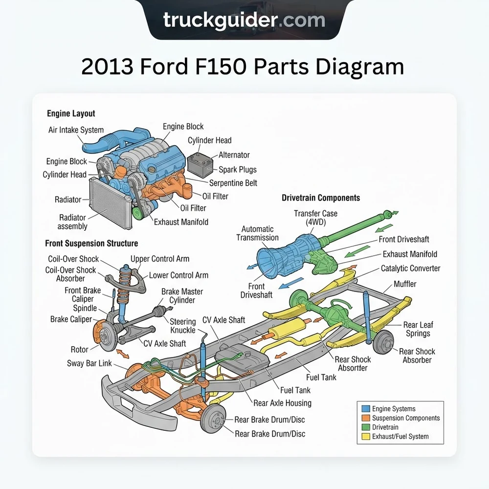
How to Read the 2013 Ford F150 Parts Diagram Step by Step
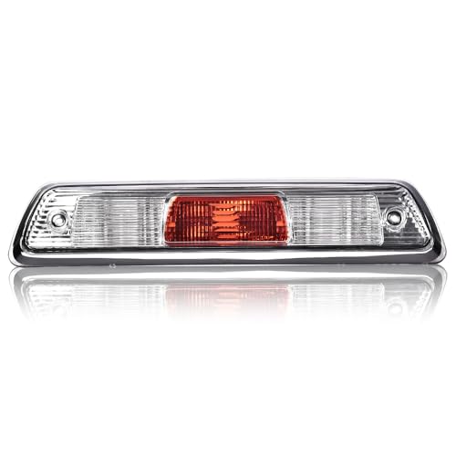


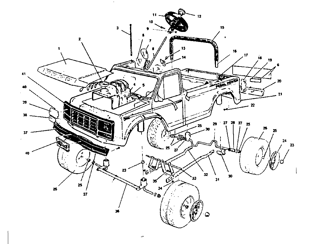
Deconstructing an OEM Ford technical illustration demands a structured workflow. Unlike general pictorial guides, factory technical illustrations utilize standardized callout protocols developed by Ford Motorcraft engineering. Following this multi-stage decoding process prevents component mismatch, incorrect harness orders, and mismatched chassis hardware.


Decode the Vehicle Identification Number (VIN) for Platform Build Attributes: Begin by capturing the 17-digit VIN located on the driver-side lower windshield corner or the Federal Certification Safety Label on the B-pillar. In the 2013 model year, the eighth character designates the engine configuration (e.g.,
Cfor 3.7L Ti-VCT V6,Ffor 5.0L Ti-VCT V8,Tfor 3.5L EcoBoost V6, or6for 6.2L 2-valve V8). OEM schematics isolate subassemblies based on this engine code, vehicle wheelbase (from 126 inches on standard regular cabs to 163 inches on SuperCab 8-foot beds), and final drive axle ratios (axle codes such asL6for 3.73 electronic locking orH9for 3.55 limited slip). Verifying these parameters ensures the exploded view corresponds directly to your truck’s physical drivetrain layout.Isolate the Primary Mechanical Subsystem and Structural Assembly: Locate the target assembly within Ford’s master catalog indexing system. Factory catalogs segment the vehicle into primary functional categories: Group 1000 (Engine and Powertrain), Group 2000 (Chassis and Brakes), Group 3000 (Steering and Front Suspension), Group 4000 (Driveline and Rear Axle), Group 5000 (Frame and Exhaust), and Group 7000 (Transmission). When diagnosing an issue such as steering drift or clunking over irregular pavement, select Group 3000 to pull the front suspension exploded schematic rather than a generic steering assembly overview.
Distinguish the Diagram Callout Number from the Complete Ford Base Part Number: Exploded views display numerical labels termed callout numbers (or illustration key numbers). A callout number is generally a 4- to 5-digit number representing the central “base part number” across all Ford lines, rather than the complete, orderable part number. For example, callout
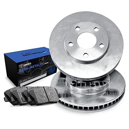
2001identifies front brake pads,3078designates the lower control arm, and6010denotes the bare engine cylinder block. The complete part number follows a 3-part anatomy:[Prefix]-[Base]-[Suffix]. The prefix (e.g.,DL3Zfor a 2013 F-150 program part) indicates the design group, vehicle line, and engineering office. The suffix (e.g.,-AA,-B) tracks revision changes and engineering updates.Cross-Reference with Ford Motorcraft Catalog Data and Production Date Breaks: Once the base callout is identified on the graphic layout, reference the catalog BOM index adjacent to the drawing. Cross-examine the production date breaks listed in the data table. The 2013 model year ran assembly from roughly August 2012 through August 2013, with a mid-year running change occurring around February 4, 2013, affecting powertrain control module (PCM) wire harnesses, transmission molded lead frames, and turbocharger coolant fittings. Always confirm that the production date stamped on your vehicle B-pillar matches the date-break filter of the schematic view.
When referencing base numbers on a 2013 ford f150 parts diagram, identical callout numbers are mirrored for symmetrical components. Ford catalogs append a modifier or list separate line items for LH (Driver Side, typically odd-numbered suffixes or sub-callouts) and RH (Passenger Side, typically even-numbered suffixes). For example, base callout 3A130 represents the outer tie-rod end, but physical driver and passenger linkages carry distinct part numbers with opposing thread orientations.
2013 Ford F150 Parts Diagram: Primary System Assemblies


The 2013 Ford F-150 incorporates diverse mechanical, electronic, and structural sub-assemblies. The factory technical manual provides dedicated system schematics for each structural tier. Mastering these major mechanical systems allows mechanics to execute precision repairs while maintaining factory tolerances.
Powertrain and Engine Assembly Blueprint Configurations


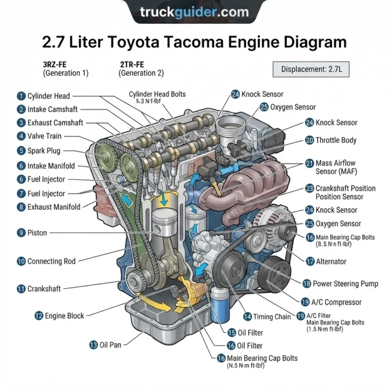
The 2013 powertrain schematic catalogs four distinct engine architectures. The most widely referenced layout covers the twin-turbocharged 3.5L EcoBoost (D35). In this engine layout, the schematic highlights critical high-wear subassemblies: twin BorgWarner turbochargers mounted directly to cast-iron exhaust manifolds, dual water-cooled bearing cartridges, and oil feed/return circuits. Callout 6A968 represents the turbocharger coolant supply and return lines, which utilize quick-connect fittings and internal O-rings prone to heat embrittlement. Refer to our guide on F-150 EcoBoost vacuum line routing for deeper intake tract diagnostics. On 5.0L Coyote V8 schematics, callout 8501 denotes the mechanical water pump, which underwent a design change mid-2013 from a 3-bolt pulley pattern to a 4-bolt pulley hub configuration—an engineering variation clearly demarcated in the subassembly exploded view.
6R80 Transmission and Transfer Case Layout Schematics
Drivetrain drawings center on the Ford 6R80 six-speed automatic transmission. The core exploded layout details the aluminum bellhousing, planetary gearsets, torque converter (base 7902), and mechatronic valve body assembly (base 7A100). Within the valve body schematic, a high-frequency replacement component is callout 7G276, the transmission molded lead frame connector. This module houses the output shaft speed (OSS) sensor, turbine shaft speed (TSS) sensor, and transmission range sensor. For 4×4 models, the output shaft of the 6R80 couples directly to the transfer case schematic—predominantly the BorgWarner 4419 (part-time electronic shift-on-the-fly) or BorgWarner 4417 (torque-on-demand all-wheel-drive found in higher trim packages like Lariat, King Ranch, and Platinum). The transfer case shift motor (base 7G360) is depicted on the exterior housing, secured by three M6x1.0 fasteners torqued to 89 lb-in (10 Nm).
When servicing the 6R80 mechatronic unit shown in the transmission schematic, never drop the valve body without first pulling the white plastic locking tab on the internal mechatronic sleeve (base 7F401). Forcing the valve body downward without disengaging the bulkhead connector will shear the molded lead frame pins, requiring total lead frame replacement.
Front Suspension and Steering Component Architecture
The front chassis schematic demonstrates an independent double-wishbone architecture supported by a coil-over-strut shock absorber (base 18124). The upper control arm (base 3084/3085) connects to the cast iron steering knuckle via an integral ball joint, while the lower control arm (base 3078/3079) handles primary dynamic loading through heavy-duty hydro-bushings. The defining feature of the standard 2013 F-150 front layout is the Electronic Power Assist Steering (EPAS) steering gear assembly (base 3504). The EPAS system integrates an electric brushless motor, internal ball-nut drive mechanism, and Electronic Control Unit (ECU) directly onto the steering rack housing, eliminating hydraulic pumps, high-pressure lines, and fluid reservoirs. The tie-rod ends (inner 3280, outer 3A130) thread directly into the EPAS rack gear, with the outer tie rod nut requiring a final torque specification of 111 lb-ft (150 Nm).


Factory Front Suspension Fastener Torque Ratings (per OEM Service Manual):
• Lower Control Arm to Frame Bolts: 221 lb-ft (300 Nm)
• Upper Control Arm to Frame Nuts: 85 lb-ft (115 Nm)
• Lower Strut Mount Bolt (M18 Grade 10.9): 406 lb-ft (550 Nm)
• Upper Strut Mount Nuts (3x): 35 lb-ft (47 Nm)
• Tie Rod Outer End to Knuckle: 111 lb-ft (150 Nm)
Rear Axle and Leaf Spring Structural Overview


The rear suspension and driveline diagram details a hotchkiss-type live axle setup suspended by asymmetric multi-leaf spring packs (base 5560). Depending on engine displacement and the presence of the Heavy-Duty Payload Package (Option Code 627), the rear axle schematic displays either an 8.8-inch gear set, a 9.75-inch standard differential, or the heavy-duty 9.75HD axle featuring 7-lug hubs and thickened axle tubes. Review our comprehensive teardown on Twelfth-gen F-150 rear axle rebuilding for ring-and-pinion backlash shimming procedures. The differential carrier housing cover (base 4033) is secured by 10 or 12 bolts (torqued to 33 lb-ft / 45 Nm), and the rear shock absorbers (base 18125) are mounted in a staggered configuration—one forward of the axle tube, one aft—to counteract dynamic axle wrap under acceleration.
2013 F-150 Schematic Reference: Base Numbers and Subsystem Codes



During the production cycle of the Twelfth Generation Ford F-Series (2009–2014), engineering standards unified component categorization across light trucks. To facilitate fast lookup within an exploded 2013 ford f150 parts diagram, consult the master reference table below. This dataset links standard Ford base callout numbers to physical vehicle assemblies, functional systems, and specific model variation criteria.
| Base Number | Subsystem / Component | BOM Assembly Location | Engineering Variation & Fitment Notes |
|---|---|---|---|
| 2001 | Front Brake Pad Kit | Brake System Diagram | Dual-piston front caliper layout; includes stainless abutment clips. |
| 2B120 / 2B121 | Front Brake Caliper (RH / LH) | Brake System Diagram | Phenolic pistons; banjo bolt threads M10x1.0 (Torque: 30 lb-ft). |
| 3504 | Steering Gear / Rack Assembly | Front Steering Layout | EPAS unit on standard 2013 trims; traditional hydraulic on SVT Raptor / 6.2L. |
| 14A067 | Battery Junction Box (BJB) | Electrical & Fuse Box Diagram | Located underhood above radiator; houses high-amp maxi fuses and relays. |
| 7A098 | Automatic Transmission Fluid Filter | Transmission Internal Layout | Specific to deep-sump 6R80 transmission oil pan; features composite neck seal. |
| 6K682 | Turbocharger Assembly | Powertrain / Engine Assembly | Specific to 3.5L EcoBoost engine; separate base numbers for LH vs RH banks. |
| 4A376 | Integrated Wheel End (IWE) Actuator | Front Drive Halfshaft Schematic | Vacuum-operated hub-disconnect mechanism on 4WD configurations. |
| 12A650 | Powertrain Control Module (PCM) | Electrical Subsystem Layout | Firewall-mounted module; requires programming via Ford IDS / FDRS. |
Every structural callout depicted on the 2013 F-150 layout correlates to an entry within the factory Bill of Materials (BOM). The BOM not only reveals the baseline part number but also indicates the exact fastener configurations. For instance, in the brake system schematic, caliper bracket mounting bolts (callout 2N386) are coated with factory microencapsulated threadlocker and specify a one-time torque application of 184 lb-ft (250 Nm). Reusing these fasteners without reapplying high-strength anaerobic locker contradicts OEM service guidelines.


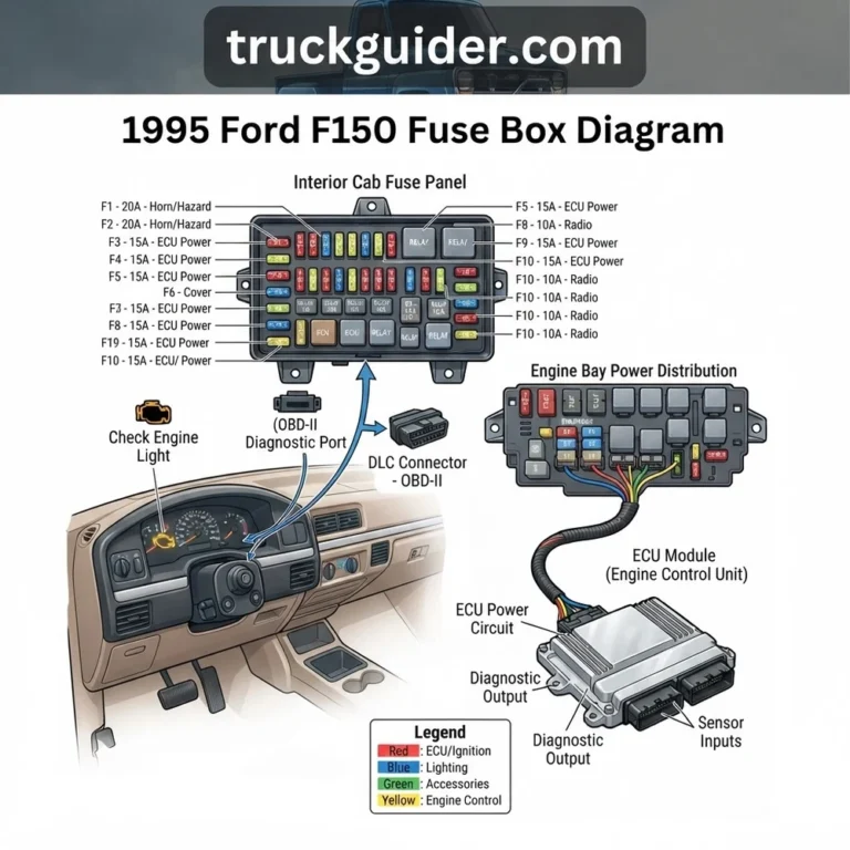
In the electrical and fuse box layout, the Battery Junction Box (base 14A067) exhibits a known structural vulnerability across 2009–2014 models: the fuel pump relay circuit (Fuse #27). In the factory diagram, Fuse 27 is designated as a 20-amp low-profile mini-fuse. Because of continuous high-amperage draw from the fuel pump driver module, the terminal socket within the fuse block can overheat, melt the plastic carrier, and cause crank/no-start conditions. Ford engineered a technical service bulletin relocation kit (Motorcraft base 14A068 / Part # EL3Z-14293-A) shown in revised electrical schematics, which relocates the circuit to a heavy-duty J-case fuse cavity (Slot #70).
Troubleshooting 2013 Ford F150 Parts Diagram Fitment Issues


Mismatches between the physical truck and schematic illustrations often arise due to running mid-year changes, engine-specific chassis modifications, or cross-referencing against adjacent model years. Understanding these common discrepancies ensures correct component procurement and eliminates costly install delays.
The most pervasive error encountered when reading a 2013 ford f150 parts diagram involves the steering gear assembly. If your truck is equipped with the standard 3.7L, 5.0L, or 3.5L EcoBoost engine, the diagram displays the Electronic Power Assist Steering (EPAS) rack. However, if you reference an SVT Raptor diagram or an F-150 equipped with the heavy-duty 6.2L V8 option, you will encounter a traditional hydraulic steering diagram featuring a power steering pump, belt pulley, fluid reservoir, and high-pressure hydraulic lines. Attempting to match an EPAS inner tie-rod or steering shaft knuckle (base 3B676) to a hydraulic chassis configuration will fail, as the input spline count and rack dimensions differ completely.
Another common misstep is relying on diagrams from adjacent model years without accounting for generational evolution:
Deviations from a 2010 Ford F-150 Parts Diagram: The 2010 model year represents the early architecture of the Twelfth Generation platform. Schematics for 2010 trucks feature older powertrain families (the two-valve and three-valve 4.6L and 5.4L Modular Triton V8 engines) mated to 4R75E or early 6R80 units. In 2011, Ford completely overhauled the powertrain line, meaning engine mounts, cooling packages, engine harnesses, and exhaust downpipes from a 2010 diagram share zero compatibility with a 2013 schematic.
Subtle Divergences in a 2014 Ford F-150 Parts Diagram: While 2013 and 2014 represent the final iterations of the twelfth generation, key running changes exist. Later 2014 models incorporated subtle alterations in the transmission lead frame connector pins, updated evaporative emission (EVAP) purge valves (base
9C915), and altered rear axle electronic parking brake wiring provisions on select late-production variants. Cross-verifying the build month on your door tag prevents cross-ordering parts with revised connector keyways.Complete Incompatibility with a 2015 Ford F-150 Parts Diagram: In 2015, Ford introduced the Thirteenth Generation platform. That overhaul brought an all-aluminum military-grade body structure, a high-strength fully boxed steel frame redesign, and a secondary generation of 3.5L and 2.7L EcoBoost engines. Body hardware, cab mounts (base
1000154), door lock actuators, control arms, and frame brackets shown on a 2015 schematic are dimensionally and mechanically incompatible with a 2013 model.
Fastener callout misidentification represents another major source of error. Fasteners on Ford exploded schematics are marked with generic callout identifiers (such as -W700000- series base codes). When ordering hardware via the diagram, verify the pitch, diameter, and grade. The lower shock absorber mounting bolt on the 2013 F-150 front suspension is a massive M18 Grade 10.9 prevailing-torque bolt. Using a standard Grade 8.8 or an SAE Grade 5 equivalent sourced from generic hardware bins creates severe structural failure risks under dynamic suspension load.



OEM Schematics vs Aftermarket Manual Diagrams Comparison
When executing complex overhauls, mechanics often must choose between official Ford factory schematics and diagrams published in aftermarket service guides like Haynes or Chilton. While aftermarket manuals provide helpful high-level instructional overviews, significant technical differences separate them from OEM engineering drawings.
| Feature / Technical Attribute | OEM Ford Factory Parts Diagram | Aftermarket Repair Manual (Haynes / Chilton) |
|---|---|---|
| BOM Component Granularity | Full exploded detail down to individual O-rings, clips, brackets, and specific bolt part numbers. | Generalized subsystem views; frequently omits secondary brackets, small seals, and retaining clips. |
| Part Number Integration | Direct link to 4-5 digit base numbers and full Ford Motorcraft catalog listings. | No factory part numbers; relies on broad, generic component terminology. |
| Production Date-Break Tracking | Pinpoints running engineering revisions by specific day, month, and assembly plant origin. | Aggregates entire generation spans (e.g., 2009–2014) into single, homogenized illustrations. |
| Fastener Specifications | Lists exact thread diameters, pitches, length dimensions, and replacement-required warnings. | Provides general torque charts at chapter ends; rarely details individual bolt dimensions. |
| Wiring & Connector Pinouts | Detailed connector face views, terminal cavity numbers, wire gauge sizes, and dual-stripe wire color codes. | Basic schematic ladder diagrams; often lacks physical connector cavity pin maps and inline disconnects. |
For routine maintenance procedures—such as swapping brake pads or replacing an alternator—an aftermarket manual provides sufficient step-by-step guidance. However, for precise driveline rebuilds, harness pin-tracing, or ordering niche sub-components like the turbocharger oil check valve (base 6B933) or IWE vacuum solenoid check valve (base 7A785), the OEM 2013 ford f150 parts diagram remains the indispensable standard. OEM schematics accurately capture the true mechanical relationships engineered into your truck by the factory, preventing misalignments, wrong part orders, and unexpected installation failures.
Frequently Asked Questions About the 2013 Ford F150 Parts Diagram
How do I decipher prefix, base, and suffix characters on a 2013 F-150 parts diagram?
The part numbering system on a 2013 F-150 utilizes a three-segment architecture. The prefix designates vehicle model year, vehicle line, and engineering responsibility (e.g., DL3Z: D for 2013, L3 for F-150, Z for Ford Customer Service Division). The base number (e.g., 2001 for brake pads or 3078 for lower control arm) identifies the functional component category common across Ford vehicle platforms. The suffix (e.g., -A, -AB, -C) designates sequential design revisions, variations in physical finish, or specific application attributes such as heavy-duty payload packaging. When searching a parts catalog via diagram callouts, the exploded graphic displays the base number, which is matched to your VIN to determine the correct prefix and latest revision suffix.
Why does my 2013 F-150 steering rack diagram differ from the Ford Raptor schematic?
In the 2013 model year, standard consumer F-150 trucks equipped with the 3.7L V6, 5.0L V8, or 3.5L EcoBoost feature an Electronic Power Assist Steering (EPAS) rack and pinion system. This design utilizes a computer-controlled electric servo motor attached to the rack casting, eliminating hydraulic lines entirely. In contrast, the high-performance off-road 2013 SVT Raptor—as well as fleet-oriented F-150s running the 6.2L Boss V8—retained a traditional hydraulic power steering system due to high-demand desert-running cooling requirements and mechanical clearance constraints around the 6.2L cast-iron block. Consequently, the Raptor steering diagram displays a hydraulic pump, remote reservoir, fluid cooler, and hydraulic lines that do not exist on standard 2013 truck diagrams.
Where can I locate the fuse and relay designations on a 2013 F-150 electrical layout?
The electrical layout of the 2013 F-150 is bifurcated into two primary distribution hubs illustrated in separate schematics. The underhood Battery Junction Box (BJB), located directly above the radiator shroud, houses high-current Maxi-fuses, J-case fuses, and system relays for powertrain components, ABS, electric radiator fans, and the EPAS system. The passenger compartment Body Control Module (BCM)—often referred to as the Smart Junction Box (SJB)—is mounted behind the lower kick panel in the front passenger footwell. The BCM layout catalogs mini-fuses protecting interior circuits, body lighting, cluster electronics, power windows, and central locking solenoids.
How do build date breaks affect parts diagram accuracy for the 2013 model year?


Mid-cycle production revisions frequently prompt Ford to issue revised engineering parts midway through a vehicle run. On the 2013 F-150, a significant date-break occurred on February 4, 2013. Models manufactured before this date use specific transmission internal connector pin configurations, early-style water pump pulley hubs on the 5.0L engine, and distinct turbo coolant line O-ring compositions on the 3.5L EcoBoost. Trucks assembled after this date feature revised components. Always inspect the safety compliance decal on your driver-side door jamb (which displays the production month and year) and select the corresponding diagram segment matching that specific manufacturing window.
What does the term “Integrated Wheel End” refer to on a 2013 F-150 4×4 front axle diagram?
The Integrated Wheel End (IWE) assembly—identified under base callout 4A376 on front axle and hub schematics—is a vacuum-operated locking hub mechanism fitted between the wheel hub and the outer CV joint of the front drive halfshaft. When the truck operates in 2WD mode with the engine running, engine vacuum is applied to the IWE diaphragm via an engine bay vacuum solenoid (base 7A785), retracting the internal gear collar against spring pressure to disconnect the wheel hubs from the front axle halfshafts. When switched to 4WD mode, or when engine vacuum drops below a set threshold, vacuum is vented, and an internal coil spring forces the gear collar into engagement with the wheel hub, locking the front driveline together.
Step-by-Step Guide to Understanding the 2013 Ford F150 Parts Diagram
Identify – Decode the VIN’s 8th digit to verify your specific powertrain and chassis layout before ordering parts.
Locate – Find the target assembly on the master layout, noting surrounding interconnected brackets, hoses, and wiring looms.
Reference – Match the five-digit base component number on the schematic to verify correct OEM replacement part numbers.
Connect/Route – Reassemble components following diagram callout sequences, matching factory orientations for vacuum lines, brackets, and wiring retainers.
Verify – Torque all fasteners to factory structural specifications, paying close attention to torque-to-yield suspension hardware.
Troubleshoot – Check vacuum line integrity and electrical pinouts against schematic paths if warning indicators or component faults persist.