2014 GMC Sierra 1500 Fuse Box Diagram: Troubleshooting 2026

The 2014 GMC Sierra 1500 features an underhood fuse block on the driver-side engine compartment and an interior block behind the driver-side dashboard trim. Circuit 56 controls the fuel pump, while fuse 28 powers the ECU. Inspect fuses with a 12V test light before testing relay coils or terminal voltages.
📌 Key Takeaways
- Underhood block houses JCASE and Micro2 fuses; interior panel protects cabin accessory circuits.
- Critical powertrain fuses include Fuse 28 (ECU/ECM 15A) and Fuse 56 (Fuel Pump 20A).
- Battery terminal nut torque spec is 9 Nm (80 lb-in); always disconnect negative terminal before servicing blocks.
- Water intrusion or loose ground nuts under the hood frequently trigger an erratic check engine light.
- Replace blown fuses directly; consult a professional if parasitic draws persist or diagnostic codes indicate harness shorts.
Navigating the electrical architecture of the third-generation K2XX platform requires an accurate 2014 GMC Sierra 1500 fuse box diagram. Redesigned for the 2014 model year, the Sierra 1500 transitioned to a sophisticated distributed electrical network governed by high-speed GM-LAN and Controller Area Network (CAN-bus) lines. Troubleshooting sudden subsystem failures—ranging from direct-injection fuel rail loss to trailer brake controller faults—demands that technicians identify power distribution points rapidly. This technical guide delivers precise component breakdowns, terminal amperage ratings, and schematic mapping across all underhood and cabin electrical distribution centers to streamline automotive electrical diagnostics.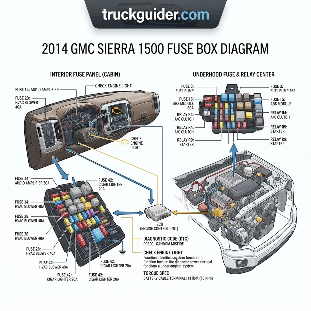
2014 GMC Sierra 1500 Fuse Box Diagram and Panel Locations



The 2014 GMC Sierra 1500 utilizes four primary power distribution centers (PDCs) to manage cabin accessories, powertrain electronics, chassis stabilization, and high-amperage electrical generation. Unlike previous GMT900 platforms, the K2XX platform isolates high-amperage starting and charging loads onto a dedicated battery-mounted distribution center while segregating sensitive solid-state logic into dual instrument panel junctions. Correctly reading the 2014 GMC Sierra 1500 fuse box diagram requires understanding the physical placement and access protocol for each distinct assembly.


Before probing any fuse panel on the 2014 Sierra 1500, verify that the ignition switch is in the OFF position and the Keyless Entry / Retained Accessory Power (RAP) has completely timed out (minimum 10 minutes). Waking up the CAN-bus communication lines during active circuit probing can induce false parasitic drain readings across instrument cluster lines.
Underhood Engine Compartment Distribution Block


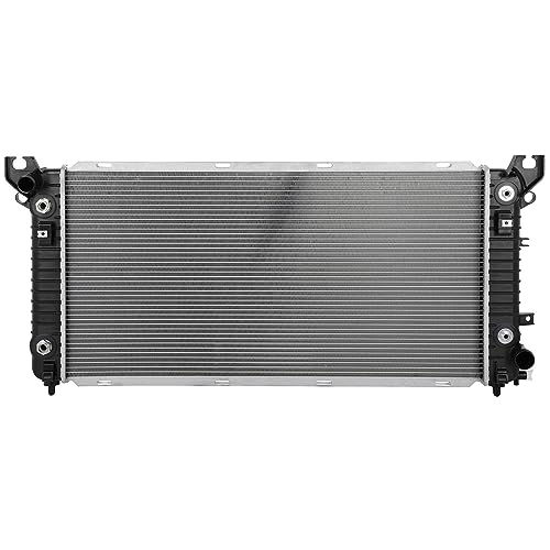

The main underhood fuse block is located on the driver side of the engine bay, positioned between the engine coolant surge tank and the driver-side fender well. This panel houses critical powertrain fuses, solid-state relays, and the primary feeds for the powertrain control module (PCM/ECM), fuel pump flow control module, and ABS pump motor. To access the panel, depress the four perimeter retaining tabs located on the outer edge of the molded cover and pull straight up. A secondary schema and legend are heat-stamped onto the underside of the plastic lid, serving as an on-vehicle 2014 GMC Sierra 1500 fuse box diagram cross-reference.
Left-Hand Instrument Panel Fuse Block
The left instrument panel (IP) junction block is integrated into the driver-side outboard end of the dashboard. This distribution center supplies low-current power to the Body Control Module (BCM), diagnostic link connector (DLC), instrument cluster, and driver door control module. Access requires opening the driver door completely, inserting a non-marring trim tool beneath the lower edge of the driver-side dash end cap, and pulling outward perpendicular to the dashboard to release the three metal retainers.
Right-Hand Dash Junction Block
Positioned symmetrically to the driver-side panel, the right instrument panel fuse block sits behind the passenger-side dash end cap. This unit isolates passenger convenience circuits, secondary infotainment hardware, auxiliary heating/ventilation actuators, and seat heater modules. Access involves opening the passenger front door, unsnapping the passenger dashboard end cover, and pulling the panel away from the sub-dash support bracket.
High-Current Battery Mounted Fuse Block


The 2014 GMC Sierra 1500 features a dedicated high-amp busbar distribution block mounted directly on the top surface of the main 12V battery. This master junction receives unfused current directly from the positive battery post and distributes power across high-amperage fusible links directly to the Electric Power Steering (EPS) gear, the starter motor solenoid, and the 150A/170A engine alternator feed. Servicing requires releasing the red locking tab on the terminal protective shroud and removing the retained hex nuts securing the high-amperage lugs.


| Panel Designation | Physical Location | Retainer / Fastener Type | Primary Circuits Managed |
|---|---|---|---|
| Engine Compartment Fuse Block | Driver side engine bay, forward of master cylinder | Molded plastic snap latches (4) | ECU, Fuel Pump, ABS, Transmission, Cooling Fans |
| Left Instrument Panel (IP) Block | Driver dashboard outboard lateral end cap | Push-in spring steel trim clips | BCM, OBD-II Port, Cluster, Steering Column Lock |
| Right Instrument Panel (IP) Block | Passenger dashboard lateral end cap | Push-in spring steel trim clips | HVAC Blower, Accessory Sockets, Heated Seats |
| Battery-Top Power Distribution Block | Mounted directly above the 12V positive terminal | Snap cover + 10mm / 13mm hex terminal nuts | EPS Rack, Starter Motor, Alternator Charging Loop |
Battery Distribution Block Terminal Fastener Torque Spec: When reinstalling the high-current fusible link nuts on the battery-top block, torque the M6 nuts to 9 N·m (80 lb-in) and the M8 battery clamp nut to 12 N·m (106 lb-in). Under-torquing leads to high resistance, intermittent communication drops, and low system voltage codes.
Underhood and Cabin 2014 GMC Sierra Fuse Block Circuit Guide

The 2014 redesign migrated significant circuit protection from standard ATO/ATC blade fuses to high-density Micro2 and Micro3 blade footprints, low-profile J-Case cartridge fuses, and solid-state micro relays. Micro2 fuses provide compact circuit protection across engine management inputs, while J-Case components safeguard high-load motor circuits such as the electronic transfer case actuator and dual cooling fan assemblies.
The table below provides a focused circuit reference for high-failure and critical powertrain systems mapped from the primary 2014 GMC Sierra 1500 fuse box diagram under the hood and within the cabin. When isolating intermittent engine stall conditions or communication drops across the network, consult our comprehensive K2XX charging system diagnostic page to verify steady-state alternator ripple and reference grounds.
| Circuit / Position | Fuse Type | Rating (Amps) | Subsystem / Components Protected |
|---|---|---|---|
| F01 (Underhood) | J-Case | 40A | Antilock Brake System (ABS) Pump Motor |
| F08 (Underhood) | J-Case | 50A | Engine Cooling Fan 1 (Primary High-Flow Assembly) |
| F16 (Underhood) | Micro2 | 15A | Fuel Injector Bank A (Direct Injection High-Pressure Rail) |
| F17 (Underhood) | Micro2 | 15A | Fuel Injector Bank B (Direct Injection High-Pressure Rail) |
| F22 (Underhood) | Micro2 | 25A | Engine Control Module (ECU / ECM Logic Power) |
| F28 (Underhood) | Micro2 | 15A | Engine Powertrain Actuators, VVT Solenoids, Evap Purge |
| F39 (Underhood) | Micro2 | 10A | Variable Displacement Oil Pump Solenoid, VDV Valve |
| F44 (Underhood) | Micro2 | 20A | Fuel Pump Power Module (FPPM Battery Supply) |
| F52 (Underhood) | J-Case | 40A | Trailer Brake Control Module (ITBC Feed) |
| F01 (Left IP) | Micro2 | 30A | Body Control Module (BCM 1 – Exterior Lighting Logic) |
| F04 (Left IP) | Micro2 | 10A | Data Link Connector (OBD-II Port PIN 16 B+ Feed) |
| F18 (Left IP) | Micro2 | 10A | Instrument Panel Cluster (IPC Gateway) |
| F03 (Right IP) | J-Case | 40A | Front HVAC Blower Motor Assembly |
| F12 (Right IP) | Micro2 | 20A | Cigar Lighter / 12V Auxiliary Power Outlets Front |
| BAT-01 (Battery Top) | Bolt-On MIDI | 125A | Electronic Power Steering (EPS Rack & Pinion Logic) |
| BAT-02 (Battery Top) | Bolt-On MIDI | 175A | Engine Starter Motor Solenoid High Current Inrush |
Never substitute a blown Micro2 or J-Case fuse with a higher amperage rating or mechanical bridging wire. The wiring harnesses on the 2014 Sierra 1500 utilize thin-wall cross-linked polyethylene (TXL) insulation designed strictly for the engineered circuit load. Over-fusing risks harness thermal degradation, connector melting, and permanent BCM solid-state driver failure.
Blown Fuse Symptoms, Check Engine Light, and ECU Malfunctions


When a circuit protection device fails on a direct-injected 2014 GMC Sierra 1500 (equipped with the 4.3L LV3, 5.3L L83, or 6.2L L86 EcoTec3 engine), the symptoms rarely present as a straightforward, isolated accessory loss. Modern power-management systems link engine hardware to chassis stability and cabin monitoring modules. A single open fuse can illuminate the check engine light, trigger multiple diagnostic code entries across different controllers, and place the powertrain into limp-home mode.


Correlating symptoms to circuit failures mapped on the 2014 GMC Sierra 1500 fuse box diagram enables precise diagnosis of the following root causes:
- Loss of Fuel Rail Pressure and Instant Stall (Fuse F22 or F44): The EcoTec3 direct injection system relies on an electric low-pressure lift pump in the fuel tank to feed the mechanical high-pressure pump mounted beneath the intake manifold. If underhood Fuse F44 blows, the Fuel Pump Flow Control Module ceases communication, generating diagnostic code P069E (Fuel Pump Control Module Requested MIL) and U0109 (Lost Communication With Fuel Pump Module). The engine cranks indefinitely but fails to build fuel rail pressure.
- VVT Timing Lockout and Camshaft Phasing Errors (Fuse F28): Variable valve timing (VVT) controls the physical advance and retard of the camshaft relative to the crankshaft sprocket. The camshaft actuator magnet relies on uninterrupted 12V switched ignition power through underhood Fuse F28. If an internal short occurs in an O2 sensor heater on that same loop, Fuse F28 opens. This immediately de-energizes the VVT solenoid, causing the phaser to park at base timing. The engine sets diagnostic code P0010 (Camshaft Position Actuator Circuit) or P0011 (Timing Over-Advanced), leading mechanics to erroneously suspect a stretched timing chain or failed mechanical tensioner. Review our deep-dive on VVT solenoid diagnosis before disassembling the front timing cover.
- Erratic Oil Pressure Gauge and Active Fuel Management Lockout (Fuse F39): The Gen-V small block utilizes a dual-stage, variable-displacement vane-type oil pump managed by an electronic solenoid valve inside the oil pan. Fuse F39 supplies power to this solenoid. A blown F39 fuse defaults the variable oil pump to its high-pressure relief mechanical state, disabling cylinder deactivation (AFM). The cluster displays erratic sweep readings, the check engine light illuminates, and the ECU stores diagnostic code P06DD (Engine Oil Pressure Control Circuit Stuck Off) or P0521 (Engine Oil Pressure Sensor Performance).
- No-Communication across Scan Tool via OBD-II (Left IP Fuse F04): When connecting a scan tool to read a diagnostic code and encountering a “Linking Error” or “Vehicle Not Responding” status, the issue is almost always a loss of battery voltage on Pin 16 of the Data Link Connector. In the 2014 Sierra, this circuit is routed directly through Left-Hand IP Fuse F04. This circuit shares power with auxiliary cabin ports; plugging high-draw phone chargers or inverters into dash sockets frequently blows this fuse, disabling all OBD-II scanner communication with the ECU.
- Active Grille Shutter Jamming and Abnormal Coolant Flow (Fuse F08 / F13): The 2014 Sierra features aerodynamic active grille shutters positioned forward of the radiator to regulate engine thermal efficiency and coolant flow aerodynamics. When debris binds the lower or upper shutter vanes, the high-draw stall condition blows underhood Fuse F13. This cuts feedback to the cooling fan control system, forcing the radiator cooling fan to default to 100% full-speed continuous run mode to protect the engine, accompanied by diagnostic code U1510.
Testing 2014 GMC Sierra Fuses with Multimeter and OBD-II Diagnostics



Pulling individual fuses from the 2014 Sierra 1500 fuse panels to perform visual inspections is inefficient and expands the female terminal receivers within the junction block, causing intermittent high-resistance terminal spread. A professional technician tests circuits in place using a digital multimeter (DMM) calibrated to DC millivolts/volts or a high-impedance logic-safe test light, cross-referencing electrical anomalies with live OBD-II data.
- Prepare the Vehicle Electrical System: Turn the ignition key to the ON/RUN position with the engine off (KOEO). Ensure the transmission is in PARK and secure the parking brake. If diagnosing cabin accessory circuits controlled by the BCM, close all doors or manually depress the door latch switches to prevent cabin interior lamps from back-feeding auxiliary lines during continuity checks.
- Establish an Accurate Chassis Reference Ground: Attach the black (negative) lead of the digital multimeter to a clean, unpainted chassis ground or the dedicated negative ground stud located on the driver-side inner fender apron. Avoid clamping to rusted brackets, anodized bolts, or loose ground straps, as floating ground potential produces inaccurate voltage measurements. Consult our verified chassis grounding points guide for exact factory ground terminal locations across the K2XX platform.
- Execute In-Place Voltage Drop Probing: Configure the multimeter to read DC Volts (auto-ranging). Every automotive blade fuse (Micro2, Mini, Maxi) features two exposed metallic test points on its exposed top plastic casing. Place the sharp red multimeter probe tip sequentially onto Test Point A, then Test Point B of each fuse:
- Condition 1 (Operating Normally): Multi-meter displays full system battery voltage (approximately 12.2V to 12.6V DC) on both test points. The circuit is closed, energized, and functional.
- Condition 2 (Blown / Open Circuit): Multimeter displays 12V+ on one test point, and precisely 0.00V on the opposite test point. This confirms current reaches the line-side terminal, but the internal fusible element is severed.
- Condition 3 (Unenergized Circuit): Multimeter displays 0.00V on both test points. The fuse is not blown; rather, its controlling relay, ignition switch contact, or BCM output driver has not enabled that circuit branch.
- Perform Continuity Verification on Removed Fuses: If a fuse exhibits zero volts on both test pads and requires bench testing, extract it using an insulated fuse puller tool. Switch the multimeter to Resistance (Ohms – Ω) or Continuity Beeper mode. Place the DMM probes across the fuse blades. A functional fuse must register lower than 0.2 Ω with an audible tone. If the display reads “OL” (Open Loop) or infinite resistance, replace the fuse.
- Correlate Electrical Failures with OBD-II Live Data: Connect an advanced OBD-II diagnostic scan tool to Pin 16 of the Data Link Connector. Access the PCM/ECM data stream and review live sensor parameters for:
- IGN1 / Switched System Voltage: Confirms power flow past ignition relays.
- Fuel Rail Pressure Sensor: Validates fuel pump power integrity.
- Desired vs. Actual Camshaft Angle: Confirms VVT solenoid circuit power before tearing down timing chain assemblies.
- Engine Coolant Temperature (ECT) and Fan Duty Cycle: Confirms the PCM can command coolant flow relays without solid-state hardware tripping.
Clear stored DTCs only after replacing the defective circuit protection device and testing the system under dynamic load.
2014 GMC Sierra 1500 Fuse Box Electrical FAQ
Why does my 2014 Sierra 1500 trailer brake fuse keep blowing when towing?
The underhood Fuse F52 (40A J-Case) protects the Integrated Trailer Brake Control Module (ITBCM). Frequent failure of this fuse is almost universally caused by an intermittent short-to-ground in the electric brake electromagnets on the trailer axles or pinched wiring inside the 7-way bumper connector harness. Remove the 7-way plug, inspect the spring-loaded pins for green galvanic corrosion, and measure the resistance of the trailer brake circuit at the trailer tongue; an operational dual-axle brake setup should measure between 1.5 Ω and 2.0 Ω. A reading below 1.2 Ω will pull excessive current and trip the 40A fuse instantly when applying maximum gain.
Can a blown fuse cause a false oil pressure gauge reading or check engine light?
Yes. Underhood Fuse F39 directly supplies 12V power to the variable displacement oil pump control solenoid located in the lower oil pan. When this fuse opens, the oil pump mechanism remains mechanically locked into its maximum displacement mode. The engine oil pressure sensor detects erratic mechanical oil pressure curves relative to RPM, prompting the ECM to set diagnostic code P06DD and trigger the check engine light. Technicians frequently misdiagnose this as a failed oil pressure sending unit or worn oil pump bearings when the actual fault is an open 10A fuse.


What causes complete loss of power steering and a “Service StabiliTrak” warning?
The 2014 GMC Sierra 1500 uses an Electric Power Steering (EPS) belt-driven rack that draws up to 110 Amps during stationary low-speed turning maneuvers. Power for this unit routes exclusively through the high-current 125A bolt-on MIDI fuse (BAT-01) integrated into the battery-top power distribution center. If this fuse blows due to an internal steering rack short or loose high-amperage terminal stud, manual steering effort increases drastically, StabiliTrak is disabled, and communication codes U0131 (Lost Communication With Power Steering Module) populate the ABS and ECM.
How do I identify which fuse powers the 2014 Sierra 1500 fuel pump?


On the 2014 model year, the in-tank fuel pump is not powered by a conventional mechanical relay. Instead, an electronic Fuel Pump Power Module (FPPM) mounted adjacent to the spare tire carrier regulates pump speed via pulse-width modulation (PWM). The main unswitched battery feed for this module originates from underhood Fuse F44, a 20A Micro2 fuse labeled “F/PUMP” or “FUEL PUMP” on the 2014 GMC Sierra 1500 fuse box diagram lid. If F44 blows, the truck will crank normally via the starter but will never ignite due to zero fuel supply.
Why does my OBD-II scanner show no power when plugged into the 2014 Sierra?
Pin 16 of the standardized 16-pin OBD-II port supplies constant 12V DC power to power diagnostic hand tools, code readers, and pass-through interfaces. In the 2014 Sierra 1500, this terminal is protected by Left-Hand Instrument Panel Fuse F04 (10A Micro2). This fuse frequently blows if metal coins or foreign conductive debris enter the 12V dash auxiliary power sockets or cigarette lighter receivers, as these systems share common battery line feeds through the interior cabin distribution block.
Step-by-Step Guide to Understanding the 2014 Gmc Sierra 1500 Fuse Box Diagram
Identify – Note malfunctioning truck circuits and scan OBD-II ports for active diagnostic codes.
Locate – Find the target underhood or cabin fuse block and remove the protective cover.
Reference – Cross-check the blown circuit against the diagram for correct fuse slot and amp rating.
Connect/Route – Replace damaged fuses using a fuse puller and torque power studs to 9 Nm torque spec.
Verify – Turn the ignition on, confirm circuit restoration, and clear any remaining check engine light.
Troubleshoot – Test terminal voltage and check for short circuits if replacement fuses blow repeatedly.