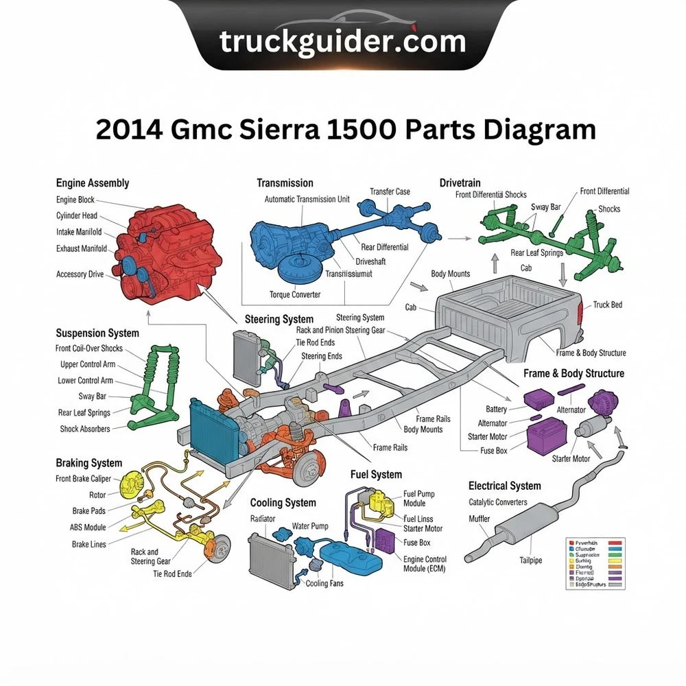
2014 GMC Sierra 1500 Parts Diagram: 2026 System Layout

The 2014 GMC Sierra 1500 parts diagram details the mechanical structure and system configuration across the K2XX platform. It provides exploded schematics for the EcoTec3 engine lineup (4.3L LV3, 5.3L L83, 6.2L L86), 6L80 6-speed automatic transmission, independent front suspension, and cabin electrical distribution blocks, detailing OEM fastener locations and assembly hierarchy.
📌 Key Takeaways
- The 2014 Sierra 1500 utilizes the K2XX platform, featuring EcoTec3 direct injection engines with distinct 15-character VIN engine identifiers (C for 4.3L, C/R for 5.3L, J for 6.2L).
- Underhood fuse blocks (X50A) separate engine control circuits from the interior body control module (BCM) located behind the driver-side lower dash.
- Front wheel hub assembly mounting bolts require a torque specification of 133 lb-ft (180 Nm), while lower ball joint pinch bolts torque to 37 lb-ft plus 120-140 degrees.
- Primary high-mileage failure points include the AFM/DoD lifter system, vacuum pump failure near the serpentine loop, and transmission thermal bypass valve sticking.
- Routine sensor swaps, brake servicing, and bolt-on component replacements are direct DIY tasks; internal transmission or valve-body servicing requires dealer-level scan tools.
The 2014 model year represents a watershed moment for General Motors full-size trucks, marking the formal introduction of the K2XX platform for the light-duty segment. When you consult a 2014 GMC Sierra 1500 parts diagram, you are looking at a fundamentally re-engineered vehicle architecture that shares virtually no exterior body panels, interior structural brackets, or engine assemblies with its GMT900 predecessor. Navigating an exploded OEM schematic requires a precise understanding of GM catalog indexing, sub-assembly groupings, and vehicle-specific options. This guide provides certified technicians and experienced builders with an exhaustive technical roadmap to interpret schematics, identify exact part supersessions, cross-reference assembly configurations, and execute repair procedures with factory-grade precision.
K2XX Platform Architecture and 2014 Sierra 1500 Schematic Structure


To accurately interpret any factory exploded view, you must first recognize the structural boundaries of the 2014 GMC Sierra 1500 layout. The 2014 Sierra 1500 debuted on the newly engineered K2XX platform, featuring an ultra-high-strength steel cab cage, fully boxed hydroformed frame rails, shear-style body mounts, and a ground-up redesign of the powertrain and electrical harness architecture. Because of this phased platform rollout, GM cataloging for model year 2014 carries an essential caveat: while the half-ton (1500) models advanced to the K2XX architecture, the heavy-duty variants—the 2014 GMC Sierra 2500HD and 3500HD—remained on the previous-generation GMT900 platform for an additional production year.


Attempting to apply a generic “2014 GMC Sierra” schematic to a half-ton chassis without isolating the 1500 designation will inevitably lead to catalog errors. Front-end suspension geometry, steering gear, frame horns, and body mounting positions differ completely between the K2XX 1500 and the GMT900 HD platforms. When consulting GM Genuine Parts or ACDelco schematics, your foundational reference must always be the 17-digit Vehicle Identification Number (VIN). The 10th digit designates the model year (“E” for 2014), while the 4th and 5th digits confirm the chassis line and drive configuration (e.g., “TK” for GMC 4WD, “TC” for GMC 2WD).
Never order steering, suspension, or body structural parts for a 2014 Sierra 1500 using heavy-duty catalog pages. The 2014 2500HD/3500HD models retained the GMT900 platform featuring torsion bar front suspensions and hydraulic power steering, whereas the 2014 Sierra 1500 uses an independent coil-over-strut configuration and an electronic rack-and-pinion steering gear.
Equally critical to schematic navigation is the Service Parts Identification (SPID) label, located inside the glove box. GM parts schematics are organized around three-character Regular Production Option (RPO) codes. An exploded parts view often displays multiple variations of a single sub-system—such as leaf springs, alternators, or differential carriers—on the same diagram plate. Without matching the diagram’s conditional callout notes to your truck’s specific RPO codes (such as Z71 for Off-Road Suspension, NHT for Max Trailering, or JL4 for StabiliTrak), selecting the correct baseline part number is impossible. Reviewing the K2XX chassis wiring diagram confirms that even electrical harnesses branch uniquely based on these factory build options.
2014 GMC Sierra 1500 Parts Diagram: Major System Component Breakdown


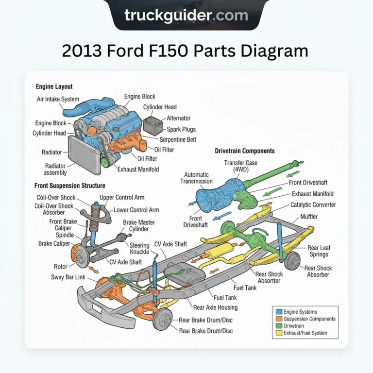
Factory exploded schematics divide the truck into functional groups: Engine, Transmission/Drivetrain, Suspension/Steering, Brakes, and Body/Electrical. Below is the mechanical breakdown of these core systems as mapped in OEM technical databases.
| System Sub-Assembly | Key OEM Schematics & Callout Components | Critical Engineering Specifications & OEM Part References |
|---|---|---|
| EcoTec3 Engine Assembly (4.3L LV3, 5.3L L83, 6.2L L86) |
• High-pressure mechanical fuel pump (cam-driven) • AFM / DFM oil control manifold assembly (VLOM) • Variable displacement vane-type oil pump • Integrated cylinder head water crossover & thermostat |
• Direct injection rail pressure: up to 2,175 psi (15 MPa) • Water Pump: GM #12685257 (ACDelco 252-1025) • Oil Pan M8 fasteners: 18 lb-ft (25 N·m) • Spark plug torque (into aluminum head): 11 lb-ft (15 N·m) |
| Hydra-Matic 6L80 Transmission & Transfer Case |
• TEHCM (Transmission Electro-Hydraulic Control Module) • Pump body with integrated fluid thermal bypass valve • Transfer case actuator motor (encoder assembly) • Front/rear output slip yoke seals and companion flanges |
• Transmission RPO: MYC (6L80 6-speed) • 2-Speed Transfer Case RPO: NQF (Magna MP3023) • 1-Speed Transfer Case RPO: NQG (Magna MP1625/1626) • Fluid spec: DEXRON-VI; Pan bolts: 106 lb-in (12 N·m) |
| Front Suspension & Steering Configuration |
• Coil-over shock/strut module assembly • Upper/lower control arms (stamped steel vs. cast aluminum) • Electric Power Steering (EPS) rack-and-pinion assembly • Front stabilizer bar and bonded thermoplastic bushings |
• EPS belt-driven rack motor operating load: 12V (up to 85A) • Lower Ball Joint to Knuckle: 37 lb-ft (50 N·m) + 90° turn • Strut-to-lower-control-arm bolts: 37 lb-ft (50 N·m) • Stabilizer end link nut: 17 lb-ft (23 N·m) |
| Four-Wheel Disc Brake System |
• Ferritic Nitro-Carburizing (FNC) Duralife brake rotors • Dual-piston front floating calipers & mounting brackets • Single-piston rear calipers with integrated park brake shoes • Camshaft-driven auxiliary mechanical vacuum pump |
• Base Brakes: RPO JD9 (17-inch wheel envelope) • Enhanced Brakes: RPO JL4 / NHT (heavy payload package) • Front Caliper Guide Pin Bolts: 28 lb-ft (38 N·m) • Caliper Bracket Mounting Bolts: 148 lb-ft (200 N·m) |
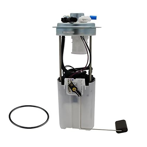
When inspecting the EcoTec3 engine assembly layout, note that GM eliminated traditional port injection entirely for 2014. The diagram schematic details a high-pressure pump mounted in the engine valley, actuated by an extra three-lobe profile on the camshaft. If you are servicing fuel components, refer to our detailed EcoTec3 torque specifications, as fuel pipe flare nuts and high-pressure rail retainers require strict one-time-use replacement policies under factory guidelines.


The steering schematic reflects another major mechanical shift: the introduction of a belt-driven rack-and-pinion Electric Power Steering (EPS) gear. The diagram does not include a hydraulic power steering pump, fluid lines, or an external reservoir. Instead, the EPS unit integrates the torque sensor, control module, and electric motor directly into the steering gear housing. Servicing this unit requires verifying the chassis harness connector integrity and reprogramming the module via GM SPS (Service Programming System) following mechanical installation.
Factory blueprints designate that all front suspension upper and lower ball joint nuts, tie-rod end nuts, and steering gear mounting bolts are Torque-to-Yield (TTY). When dismantling components referenced in front-end schematics, always source replacement prevailing-torque flanged nuts to prevent loss of clamping force under cyclic suspension loads.
Cross-Model Parts Compatibility: Sierra 1500 Blueprint Variations


Technicians often cross-reference components between the 2014 GMC Sierra 1500 and its GM stablemate, the 2014 Chevrolet Silverado 1500. While both light-duty trucks utilize the core K2XX chassis, powertrain, and cabin floor pan blueprint, substantial divergence occurs across sheet metal, exterior lighting, bumper structures, and trim level configurations. Understanding where the blueprint overlaps—and where it bifurcates—prevents costly errors when ordering body, cab, and front-clip assemblies.
| Assembly / Sub-System | Sierra 1500 Blueprint | Silverado 1500 Blueprint | Interchangeability Status |
|---|---|---|---|
| Front Fenders & Hood Sheet Metal | Fenders feature distinct squared, flared arches; hood has subtle dual center power bulges. | Fenders have pronounced two-tier stepped stamping; hood features twin high-profile strakes. | Non-Interchangeable. Inner fender structures interchange, outer skins and hinge lines diverge. |
| Headlamp & Front Grille Assemblies | Integrated projector-beam units standard; signature C-shaped perimeter LED daytime running lights. | Stacked dual-reflector halogen housings divided by a horizontal grille split-bar. | Non-Interchangeable. Header panels, bumper filler plastics, and front harness pigtails differ. |
| Chassis Frame & Core Drivetrain | Hydroformed K2XX modular frame rails; L83 5.3L / L86 6.2L; 6L80 transmission; 9.5″ or 9.76″ rear axle. | Identical hydroformed frame dimensions; identical engine, transmission, and differential mechanicals. | 100% Direct Interchange. Mounting points, hardline runs, crossmembers, and driveshafts match. |
| Suspension Damping Control | Denali trims incorporate RPO Z95 Magnetic Ride Control; SLE/SLT utilize standard passive twin-tube dampers. | High Country trims utilize standard passive dampers (Z95 MagneRide unavailable on 2014 Silverado 1500). | Trim Specific. Z95 magnetorheological shocks require dedicated sensor links and ECU schematics. |
When selecting ACDelco or GM Genuine Parts replacements for body and exterior trim, review the specific sub-model trim level (Base, SLE, SLT, or Denali). A front bumper diagram for a base Sierra 1500 shows a three-piece stamped steel configuration with unpainted textured end caps, whereas SLT and Denali diagrams illustrate fully painted end caps with integral ultrasonic park assist sensor apertures (RPO UD5). If you are servicing mechanical assemblies like the four-wheel drive transfer case, refer directly to our dedicated transfer case schematic guide to ensure proper identification between active and manual shift units across GM lines.


How to Read the 2014 GMC Sierra 1500 Parts Diagram Step by Step


Navigating an OEM exploded parts schematic efficiently requires a structured method. Factory technical diagrams use numerical callout balloons pointing to non-scaled component drawings, paired with an alphanumeric parts list table. Follow this process to identify correct part numbers without error:
- Extract the Full Vehicle Identification Number and SPID Codes: Retrieve the 17-digit VIN from the driver-side lower windshield pillar. Open the glove box and photograph the Service Parts Identification label. Note your primary mechanical codes: engine displacement (LV3 = 4.3L, L83 = 5.3L, L86 = 6.2L), transmission (MYC = 6L80), differential gear ratio (GU6 = 3.42, GT4 = 3.73), axle code (G80 = limited slip / locking), and suspension type (Z71 = off-road, Z85 = standard).
- Locate the Major Functional Assembly Category: In the OEM parts catalog index, divide your search by system group. For example, if you are sourcing an oil cooler line, do not navigate directly to “Engine Block.” Instead, access Group 01 (Engine/Cooling), Subgroup 01.520 (Oil Cooler Lines and Thermal Bypass Valves), which presents the complete circuit from oil filter adapter to the radiator tank.
- Correlate the Graphic Balloon Callout with the Index Record: Find the component on the exploded line drawing. Note the numbered balloon (e.g., callout “[14]”). Scroll down to index entry 14 in the textual ledger. You will often see three to six discrete GM part numbers listed under callout 14.
- Filter Part Numbers Using Diagram Footnotes and Option Qualifiers: In the text column adjacent to the part number, read the eligibility restrictions carefully. An entry reading “L83, 4WD, EXCEPT NHT” means that part number applies solely to 5.3L engines equipped with four-wheel drive, excluding models built with the Max Trailering package. If your truck has RPO NHT, move down to the next row matching that qualifier.
- Inspect Supersession History and Hardware Callouts: Check whether the OEM number has been superseded by a newer GM engineering release. GM regularly revises service numbers for updated seals, materials, or valving. Verify whether the balloon callout includes mounting hardware; bracket drawings frequently show attached fasteners under separate callout numbers located within dotted structural boxes.
On official GM K2XX schematics, a heavy dashed outline encircling several numbered components designates a complete pre-assembled service unit. If an exploded view shows an intermediate steering shaft, universal joint, and boot grouped within a dashed boundary labeled “[1]”, purchasing callout 1 delivers the entire unified assembly under a single part number.
Troubleshooting 2014 GMC Sierra 1500 Parts Diagram Misidentifications
Catalog lookup errors lead to downtime, incorrect repairs, and returned parts. When ordering components from 2014 Sierra schematics, be aware of these common catalog misidentifications:
- Platform Confusion Between Sierra 1500 and 2500HD/3500HD: Because GM produced GMT900 HD trucks alongside K2XX 1500 trucks in the 2014 model year, non-specialized aftermarket catalogs often lump all “2014 Sierra” components together. This leads to ordering eight-lug wheel hubs, hydraulic steering hoses, and rear leaf spring packs that do not fit the 1500 chassis. Always ensure the catalog filter explicitly isolates the 1500 (half-ton) series.
- Control Arm Metallurgy Discrepancies: During the 2014 production run, GM used both stamped steel and cast aluminum front upper and lower control arms depending on the assembly plant, production date, and RPO configuration. The ball joint taper dimensions and sway bar link mounting studs vary between stamped steel and aluminum arms. Inspect your control arms under the vehicle before referencing the suspension diagram.
- Single-Speed vs. Two-Speed Transfer Case Components: Four-wheel-drive 2014 Sierra 1500 models came equipped with either the single-speed open-differential Magna MP1625/1626 (RPO NQG) or the active two-speed Magna MP3023 (RPO NQF). The encoder motors, front case halves, and internal planetary gearsets do not interchange. Verify your dash selector switch: if it lacks a “4-LOW” setting, you are servicing an NQG single-speed transfer case.
- Silverado Sheet Metal and Bumper Swaps: Collision repairers frequently assume front bumper reinforcements and inner bumper brackets cross over between the 2014 Silverado 1500 and 2014 Sierra 1500. While the central bumper beam attaches to identical frame horns, the secondary outer corner brackets, plastic step pad retainers, and lower air deflector valances have different part numbers and mounting angles.
- Engine Mechanical Vacuum Pump vs. Hydro-Boost Configurations: The 2014 EcoTec3 engines use a mechanical, engine-driven vacuum pump (mounted on the front-left lower engine timing cover) to supply auxiliary vacuum to the brake booster. This setup replaces traditional intake manifold vacuum sourcing. Technicians unfamiliar with this diagram plate often mistake oil leaking from the vacuum pump gasket for a front crankshaft seal or steering pump leak.
2014 GMC Sierra 1500 Parts Diagram Technical Configuration FAQ
Where is the SPID RPO code sticker located on a 2014 GMC Sierra 1500?


On the 2014 Sierra 1500, the Service Parts Identification (SPID) label is affixed to the inside wall of the passenger glove box compartment (lower storage box on dual-glove-box models). If the glove box door has been replaced after an accident, the original SPID data can be regenerated by any GM dealership parts counter by querying the truck’s 17-digit VIN within the GM Global Electronic Parts Catalog (EPC).
Can I use a 2013 Sierra front suspension schematic for my 2014 Sierra 1500?
No. The 2013 Sierra 1500 belongs to the older GMT900 platform, which utilizes different suspension geometry, different front knuckle castings, and an older generation of coil-over shocks. Furthermore, the 2013 model uses hydraulic rack-and-pinion steering, whereas the 2014 Sierra 1500 features an electronic power steering (EPS) gear assembly. The suspension control arm bushings, ball joint tapers, and tie rod ends will not cross over between the 2013 and 2014 model years.


How do I determine which front brake rotor schematic applies to my truck?
Examine your glove box SPID sticker for the brake system RPO code. Most standard light-duty 2014 Sierra 1500 models feature RPO JD9 (vacuum-boosted, 17-inch wheel minimum, 330mm front rotors). Trucks configured with the Max Trailering package or specialized GVWR ratings may utilize RPO JL4 / J55 setups with larger 345mm front rotors and distinct caliper mounting brackets. Matching the diameter specified in the diagram listing to your existing rotor prevents caliper interference issues during installation.
What is the difference between ACDelco GM Original Equipment and Gold/Silver parts in schematics?


When reviewing GM parts listings, items labeled “ACDelco GM Original Equipment” (OE) or “GM Genuine Parts” represent the exact engineering release installed on the factory assembly line, adhering to all factory metallurgical, dimensional, and durability tolerances. ACDelco Gold (formerly Professional) and Silver (formerly Advantage) lines are aftermarket alternatives built to standard market specifications. For critical engine timing, direct fuel injection, and electronic steering components, source GM Original Equipment part numbers to ensure proper fitment and performance.
Why does my 2014 5.3L engine parts diagram show two different oil pan layouts?
GM engineered distinct cast-aluminum oil pans for the 2014 EcoTec3 5.3L (L83) engine to accommodate different chassis clearances. Two-wheel drive (2WD) models utilize an oil pan profile tailored for clearance around the straight structural crossmember, while four-wheel drive (4WD) models incorporate an integrated tunnel section to provide necessary drop clearance for the front differential axle housing and intermediate drive shaft. Always filter the engine oil pan schematic by the chassis drive designation (RPO TC15543 for 2WD vs. TK15543 for 4WD).
Step-by-Step Guide to Understanding the 2014 Gmc Sierra 1500 Parts Diagram
Identify – Determine your truck’s exact configuration via the VIN 8th digit to verify engine displacement (LV3, L83, L86) and cab/drivetrain setup.
Locate – Find the specific subsystem within the schematic index, such as front suspension, fuel supply, or accessory drive layout.
Reference – Cross-reference the callout numbers on the exploded schematic with the official OEM part ledger to confirm part numbers and quantities.
Connect/Route – Follow the diagram’s depicted path for hardware orientation, harness routing brackets, or fluid line snap-connector locations.
Verify – Compare the reassembled physical component against the diagram’s layout and torque all fasteners to GM factory specifications.
Troubleshoot – Inspect mating interfaces for clearance issues, electrical pin tension, or fluid leaks if abnormal noise or diagnostic trouble codes persist.