2014 Toyota Tundra Parts Diagram: 2026 System Breakdown

The 2014 Toyota Tundra parts diagram outlines major assemblies including the 5.7L 3UR-FE engine, AB60E 6-speed transmission, and double-wishbone front suspension. It details OEM sub-assemblies, schematic references, and bolt torque specifications like the 21mm lower ball joint bolts torqued to 103 lb-ft, aiding accurate structural component identification and replacement.
📌 Key Takeaways
- 3UR-FE 5.7L oil filter housing cap torques to 18 lb-ft (25 Nm) using a specialized 64mm 14-flute wrench.
- VIN 5th digit differentiates 4.0L V6 (P), 4.6L V8 (W), and 5.7L V8 (U or Y) layout structures.
- Lower control arm pivot bolts require 207 lb-ft (280 Nm) torque under suspension curb-weight load.
- Secondary air injection switching valves (bank 1 and 2) are high-failure points prone to moisture seizure.
- Perform basic exterior bolt-on and brake replacements DIY, but leave steering rack internal seals to certified technicians.
Navigating a 2014 Toyota Tundra parts diagram requires a clear understanding of the mechanical, structural, and electrical changes introduced during the second-generation platform refresh. Technicians, fleet mechanics, and advanced DIYers must frequently isolate complex subassemblies across multiple cab configurations (Regular Cab, Double Cab, and CrewMax), three distinct bed lengths, two-wheel drive (4×2) or four-wheel drive (4×4) drivelines, and three engine platforms: the 4.0L 1GR-FE V6, the 4.6L 1UR-FE V8, and the 5.7L 3UR-FE / 3UR-FBE V8. Relying on generic aftermarket illustrations often leads to misordered fasteners, mismatched harness connectors, and incorrect chassis hardware. This technical blueprint guide provides an authoritative roadmap through the factory parts catalog hierarchy, decoding OEM part numbers, callout symbols, and sub-assembly structures.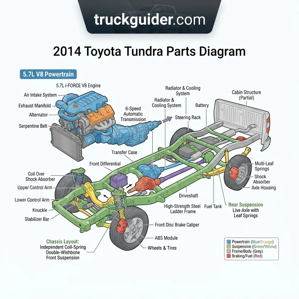
2014 Toyota Tundra Parts Diagram: Generation 2.5 Layout Overview



The 2014 model year represents the “Generation 2.5” mid-cycle facelift of the Toyota Tundra (XK50 platform). While the underlying frame structure, wheelbase dimensions, and core powertrain architectures carried over from earlier iterations, Toyota completely redesigned the exterior sheet metal, passenger cabin architecture, electrical network, and air induction packaging. When consulting a 2014 toyota tundra parts diagram within the official Toyota Electronic Parts Catalog (EPC), you must recognize how these structural revisions alter catalog navigation compared to a 2013 Toyota Tundra parts diagram or a subsequent 2015 Toyota Tundra parts diagram.



The OEM Toyota EPC categorizes all vehicle components into four primary functional groups, each assigned a dedicated numerical index:
- Group 1: Tool / Engine / Fuel: Encompasses engine mechanical blocks, cylinder heads, crankshaft and valvetrain assemblies, intake and exhaust manifolds, cooling systems, fuel injection hardware, and mounting brackets.
- Group 2: Powertrain / Chassis: Encompasses the transmission casing, torque converter, transfer case, front/rear propeller shafts, differential carriers, suspension links, steering rack, hubs, and hydraulic braking assemblies.
- Group 3: Body: Covers structural stampings, ladder frame assemblies, bed panels, doors, glass, interior dash structures, seating frameworks, and exterior trim.
- Group 4: Electrical: Details the engine control harness, main body wiring looms, junction blocks, relay centers, ECUs, sensors, lighting assemblies, and audio/navigation units.
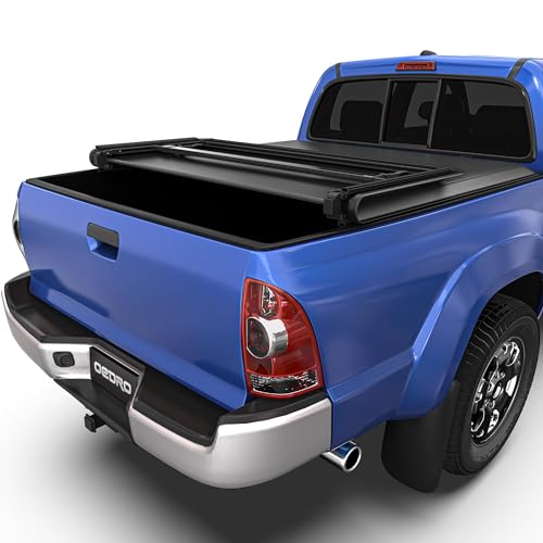
In the 2014 refresh, exterior schematics underwent major alterations. The front-end assembly diagram reflects an integrated three-piece bumper layout with steel or resin end caps, an enlarged upright front grille with a separate upper hood bulge stamping, and reshaped aerodynamic headlamp housings. The truck bed blueprint introduces a stamped rear tailgate with an integrated lip spoiler and standard reverse camera mounting provisions (PNC 86790). Inside the cabin, the dashboard schematic shows a completely redesigned instrument panel structure featuring a centralized Entune multimedia interface and a modern gauge cluster equipped with a 3.5-inch multi-information display screen.
Mechanically, the 2014 catalog eliminates several previously available configurations, including the dropped 5-speed automatic driveline variants on select chassis, standardizing 6-speed automatic transmissions across all V8 platforms. Navigating these diagrams requires confirming the production date plate located on the driver-side B-pillar, as running engineering changes during the 2014 calendar year introduced rolling supersessions for critical suspension damping components and evaporative emission (EVAP) harness configurations.
Core Assembly Schematics and Subsystem Component Breakdown



To accurately source and replace chassis, driveline, and engine hardware, technicians must understand the subassembly breakdown of each major vehicle system. The layout of the 2014 Tundra pairs high-output powertrain options with a heavy-duty chassis structure designed to handle payloads up to 2,080 pounds and maximum towing capacities exceeding 10,000 pounds.


| Subsystem & Diagram Group | Physical Location & Structural Context | Key Components & OEM Base Codes (PNC) | Configuration & Engineering Variables |
|---|---|---|---|
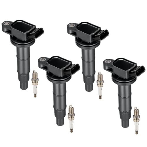
| Powertrain: Engine Assembly (Group 1: Engine/Fuel) | Front longitudinal engine bay; mounted to boxed front crossmembers via fluid-filled isolators. | • Cylinder Block (11401) • Timing Chain / Tensioner (13506 / 13540) • Water Pump Assembly (16100) • Throttle Body (22030) • Ignition Coils (90919-02256 / PNC 19070) | Three distinct engine families: – 4.0L V6 (1GR-FE): Single timing chain – 4.6L V8 (1UR-FE): 310 hp, dual VVT-i – 5.7L V8 (3UR-FE / 3UR-FBE Flex Fuel): Auxiliary engine oil cooler on tow packages |
| Transmission & Driveline (Group 2: Powertrain) | Longitudinal center tunnel; spans from engine bellhousing to rear axle differential pinion. | • Torque Converter (32000) • Valve Body Assembly (35410) • Transfer Case VF4BM (36100) • Center Support Bearing (37230) • Rear Propeller Shaft (37110) | – A760E (6-speed, 4.0L V6) – AB60E (2WD) / AB60F (4WD) (6-speed, V8 models) – Flange-to-flange driveshaft lengths vary across 145.7″, 164.6″, and 177.0″ wheelbases. |
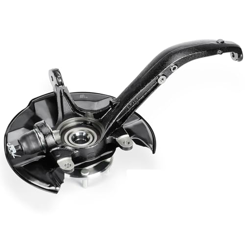
| Suspension & Steering (Group 2: Chassis) | Front independent double-wishbone subframe; rear progressive multi-leaf spring assembly on solid axle. | • Front Upper Control Arm (48066) • Front Lower Control Arm (48068) • Front Coilover Strut (48510) • Rear Leaf Spring Pack (48210) • Hydraulic Steering Rack (44250) | – Standard vs. TRD Off-Road suspension (different valving and spring rates) – Front stabilizer bar: 36mm tubular steel – Lower ball joints bolt directly to steering knuckle using high-tensile hardware. |
| Hydraulic Brake System (Group 2: Chassis) | Wheel ends and engine bay driver-side firewall (master cylinder and hydraulic booster). | • Front 4-Piston Caliper (47730 LH / 47750 RH) • Front Ventilated Rotor 354mm (43512) • Rear 2-Piston Caliper (47730A) • Rear Ventilated Rotor 345mm (42431) • ABS Hydraulic Actuator (44050) | – Integrated ABS/VSC stability system – Brake booster: Vacuum-assisted on 4.6L/5.7L V8 engines – Brake pads use integrated stainless acoustic wear indicators. |
According to factory OEM service specifications for the 2014 Tundra platform:
• Front Lower Control Arm Cam Bolts (Alignment Eccentrics): 207 N·m (153 lb-ft)
• Front Caliper Mounting Bolts (Fixed 4-Piston Housing): 137 N·m (101 lb-ft)
• Propeller Shaft Companion Flange Nuts: 88 N·m (65 lb-ft)
• Rear Leaf Spring U-Bolt Nuts (Cross-Pattern Torqued): 130 N·m (96 lb-ft)
• Automatic Transmission Fluid (AB60F): Toyota Genuine ATF WS (World Standard) — Dry Fill: 11.6 L (12.3 qt); Drain & Refill: 3.0 L (3.2 qt) at fluid check temp of 43°C–48°C (109°F–118°F).
When servicing the valvetrain or timing assembly, refer directly to a dedicated 5.7L 3UR-FE timing chain replacement guide to verify sprocket alignment marks, hydraulic tensioner retaining pin procedures, and variable valve timing (VVT-i) gear oil control valve locations, as these sub-assemblies contain closely toleranced internal passages that require precise torque sequencing.
How to Read a 2014 Toyota Tundra Parts Diagram Step by Step


Deciphering an OEM 2014 toyota tundra parts diagram requires systematic extraction of catalog data. Toyota utilizes a standardized coding format across its technical documentation, relying on Part Name Codes (PNCs) to bridge physical illustrations and actual inventory ordering numbers. Follow this disciplined workflow when navigating parts schematics in the Toyota Technical Information System (TIS) or equivalent EPC portals.
- Filter Catalogs Exclusively by Vehicle Identification Number (VIN):
Do not search solely by year, make, and model. The 2014 Tundra features dozens of sub-model variations dictated by frame length, trim packages (SR, SR5, Limited, Platinum, 1794 Edition), flex-fuel readiness, and drive layout. Entering the complete 17-digit VIN automatically filters out non-applicable schematics, suppressing irrelevant chassis or powertrain options.
- Isolate Major Systems and Select the Sub-Assembly Diagram:
Locate the primary mechanical group (e.g., “Powertrain / Chassis”), then select the specific component category (e.g., “33-01: Transaxle or Transmission Assy & Casing”). The catalog opens an exploded-view blueprint showing every structural component, fluid seal, fastener, and bracket in spatial relation to adjacent parts.
- Locate the Component Callout and Read the Part Name Code (PNC):
On the exploded schematic, components are tagged with a 5- or 6-digit numeric callout known as the Part Name Code (PNC). The PNC does not represent the final, orderable part number; instead, it identifies the generic function of the component. For example:
• 04465: Front Disc Brake Pad Kit
• 48510: Front Shock Absorber / Strut Assembly (Right Hand)
• 90919: Ignition System Hardware / Spark Plug / Coil
• 17801: Engine Air Filter Element - Interpret Fastener and Non-Standard Diagram Callouts:
Fasteners (bolts, studs, nuts, and washers) are annotated differently from serviceable components. Standard Toyota hardware callouts often begin with a 9-series designation (e.g., 90119-XXXXX for bolts with washers, 90179-XXXXX for flanged nuts). If a line points from a bolt to an assembly component, look for standard torque notations or flagged triangle/circle indicators signifying single-use, non-reusable hardware that requires replacement upon disassembly.
- Cross-Reference the PNC to Retrieve the 10- or 12-Digit OEM Part Number:
Click or cross-reference the active PNC link in the illustration’s parts list table. The system expands the PNC into the full 10-digit or 12-digit Toyota part number (formatted as
XXXXX-XXXXXorXXXXX-XXXXX-XX). The first five digits correspond to the PNC component classification, while the second five digits represent the vehicle-specific engineering application, material finish, and revision code. For example, selecting PNC 04465 on a 2014 Tundra 5.7L yields OEM part number 04465-0C020.
In Toyota chassis schematics, non-reusable components are denoted by a solid black circle (●) next to the callout, or a “Non-Reusable Part” label in the legend. On the 2014 Tundra, this includes steering rack guide mounting O-rings, front wheel bearing hub-to-knuckle O-rings (90301-A0029), driveshaft companion flange stake nuts, and copper fuel injector seat washers on direct/port injection setups. Reusing these components compromises assembly integrity and causes fluid leaks or catastrophic hub failure.
Troubleshooting 2014 Toyota Tundra Diagram Discrepancies and Catalog Errors


When utilizing a 2014 toyota tundra parts diagram for mechanical overhauls, technicians occasionally encounter discrepancies where physical components on the vehicle do not align with the digital schematic. These discrepancies stem from four primary catalog conditions: production date cutoffs, OEM part supersessions, driveline-specific packaging, and third-party illustration inaccuracies.



The 2014 model year began production in August 2013 and ran through July 2014. Vehicles manufactured between 08/2013 and 12/2013 frequently feature transitional hardware carried over from earlier designs. Always verify the MM/YY production stamp on the FMVSS label located on the driver door jamb prior to sourcing brake booster modules, evaporative air pumps, or wiring pigtails.
Addressing OEM Part Number Supersessions


Toyota continuously refines components to address service bulletins, vendor updates, or manufacturing revisions. In the catalog, an original 2014 part number may be flagged as “superseded” or “replaced by.” For instance, front lower ball joints and secondary air injection check valves have undergone multiple iterations. When a diagram lists a superseded part number, always verify whether the replacement number requires related complementary hardware—such as updated mounting studs, alternative harness connectors, or modified mounting brackets—to ensure complete compatibility.
Drive Layout Divergence: 4×2 vs. 4×4 Front Suspension Schematics
One of the most frequent catalog lookup errors involves confusing two-wheel drive (4×2) and four-wheel drive (4×4) front hub schematics. While both configurations share upper and lower control arms, the front hub and steering knuckle assemblies differ significantly:
- 4×4 Models: The front wheel hub features an open-center spline designed to accept the CV axle shaft stub, secured by a 39mm axle nut torqued to 300 N·m (221 lb-ft).
- 4×2 Models: Utilizes a dummy spindle hub cap design (PNC 43510 / 43440 omitted) without drive splines, relying on a closed inner bearing configuration.
Mismatches also occur in the transmission output and transfer case adapters. Sourcing transfer case components requires reviewing an AB60F transmission rebuild schematic to correctly distinguish between the two-wheel-drive extension housing and the four-wheel-drive intermediate adapter case casting.
Flaws in Third-Party Aftermarket Exploded Diagrams
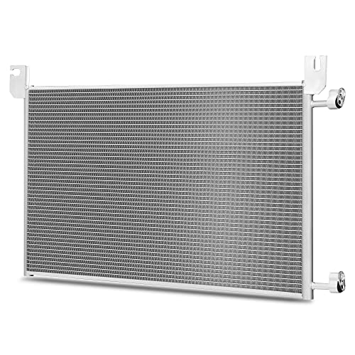
Generic aftermarket retail catalogs frequently compress or simplify exploded views to conserve digital space, collapsing complex multi-piece assemblies into single generic drawings. Common errors in aftermarket diagrams include omitting the specific placement of the differential dynamic damper, failing to illustrate the internal needle bearings within the front differential carrier, and glossing over specific O-ring seals within the A/C expansion valve piping. For complete accuracy, verify assemblies against official Toyota Technical Information System (TIS) workshop documentation to confirm that every internal clip, washer, and shim is accounted for during assembly.


2014 Toyota Tundra Parts Diagram System Inquiries and Answers
Where can technicians access authentic OEM 2014 Toyota Tundra parts schematics?


Genuine factory schematics are available directly through the Toyota Technical Information System (TIS) at techinfo.toyota.com (subscription required) or via authorized OEM Toyota parts dealer portals that interface directly with the global Toyota Electronic Parts Catalog (EPC). These sources provide precise part numbers filtered by your 17-digit VIN, capturing all running mid-year engineering changes and superseded numbers.
How do you differentiate between an AB60E and AB60F transmission diagram for the 2014 Tundra?
The transmission model code is stamped on the driver-side door jamb certification label under the “C/TR/A/TM” line (Transmission matrix). In the parts diagram, the AB60E schematic (rear-wheel drive) displays a long rear extension housing that bolts directly to the rear driveshaft slip yoke. The AB60F schematic (four-wheel drive) features a shortened rear output case designed to mate directly with the VF4BM transfer case assembly, utilizing a distinct spline seal and mounting stud configuration.
What is the difference between a Part Name Code (PNC) and a full Toyota part number?
A Part Name Code (PNC) is a generic 5- or 6-digit logical identifier used on the diagram illustration to designate a component’s function (e.g., PNC 48520 always points to the left-hand front strut assembly across all Toyota platforms). The full 10- or 12-digit part number (e.g., 48520-09U60) is the specific inventory part number required for ordering, encoding the precise vehicle model, production date range, trim options, and engineering revisions.
Why do rear leaf spring diagrams list multiple part numbers for the same 2014 model year?
Toyota equips the 2014 Tundra with varied leaf spring rates depending on cab configuration, bed length, and payload rating. A Regular Cab long bed, a Double Cab standard bed, and a CrewMax short bed each exert different static curb weights on the rear axle. Furthermore, models optioned with the TRD Off-Road package (Option Code OF) feature distinct spring rates and auxiliary leaf packs compared to baseline work-truck suspensions, resulting in unique 10-digit part numbers under the base PNC 48210.
How are wiring harness connectors identified within the electrical parts diagram?


In Group 4 (Electrical), harness schematics illustrate connector housings with a 5-digit connector code rather than a full part number. This 5-digit number corresponds to the terminal housing cavity pattern. To obtain the complete ordering number for a replacement plastic connector plug, prepend the prefix “90980-” to the 5-digit code displayed in the blueprint (e.g., connector code 11156 translates to OEM part number 90980-11156).
Step-by-Step Guide to Understanding the 2014 Toyota Tundra Parts Diagram
Identify – Determine your 2014 Tundra VIN, engine code (4.0L 1GR-FE, 4.6L 1UR-FE, or 5.7L 3UR-FE), and driveline configuration (2WD/4WD).
Locate – Isolate the target mechanical system subsection (engine mechanical, power transmission, axle/suspension, or brake hydraulics).
Reference – Find the component callout number on the exploded diagram and trace its supporting fasteners, O-rings, and bracket alignment.
Connect/Route – Follow the diagrammed routing pathways for wiring harnesses, vacuum lines, or hydraulic hoses, observing factory clip attachment points.
Verify – Confirm all installed hardware matches schematic dimensions and torque every fastener according to the diagram factory service chart specifications.
Troubleshoot – Recheck component orientation against neighboring bracket interfaces if alignment gaps, bind points, or unexpected bolt bottoming occurs.
2014 Toyota Tundra Parts Diagram: Frequently Asked Questions
What does the 2014 toyota tundra parts diagram show?
The 2014 Toyota Tundra parts diagram illustrates exploded schematics for vehicle sub-assemblies, including the 3UR-FE engine, chassis frame, steering rack, suspension linkages, and modular exhaust layout. It details OEM callout numbers, bolt sizes, retention clips, and interlocking structural configurations necessary for correct mechanical ordering and physical vehicle rebuilding.
How do I read the 2014 toyota tundra parts diagram?
Locate the primary mechanical system section, identify your truck cab configuration (Regular, Double, or CrewMax), and find the five-digit Part Base Number (PNC). Cross-reference dashed relationship lines to see mounting brackets, O-rings, and hardware. Solid lines indicate physical assemblies, while boxed callouts denote grouped sub-assembly repair packages.
What are the main components in 2014 toyota tundra parts diagram?
Key components mapped out include the front double-wishbone suspension system, steering knuckles, rear leaf springs, differential carriers, and cooling configuration. Powertrain schematics outline the serpentine belt layout, intake manifold runners, alternator brackets, variable valve timing actuators, and the dual secondary air injection pumps mounted beneath the intake plenum.
What are common problems with 2014 toyota tundra parts diagram?
Users often struggle with differentiating 2WD versus 4WD front hub assemblies and misidentifying bed-length variations for exhaust routing. Another challenge involves the plastic OEM oil filter housing assembly, which frequently binds, shears, or cracks during service, requiring cross-referencing with the upgraded aluminum Toyota OEM replacement component assembly.
Can I use 2014 toyota tundra parts diagram for DIY repair?
Yes, the diagram is invaluable for DIYers to establish disassembly sequences, determine fastener torque specifications, and prevent lost hardware during major services. It ensures you order the exact factory seal, gasket, or structural bolt required, avoiding aftermarket fitment errors on crucial systems like steering racks, brakes, and cooling loops.
What tools do I need for 2014 toyota tundra parts diagram?
You need metric sockets (10mm, 12mm, 14mm, 17mm, 19mm, 21mm, and 24mm), a 39mm axle nut socket, torque wrenches ranging from 10 to 250 lb-ft, a 64mm oil filter wrench, trim clip pliers, and a calibrated digital caliper to match hardware thread pitches with diagram callout tables.