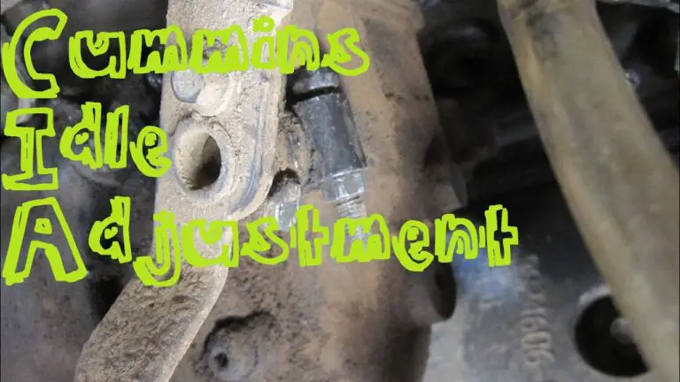
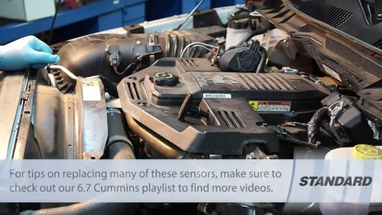
6.7 Cummins MAP Sensor Location: Symptoms, and Replacement Full Guides 2025
Introduction: The Unsung Hero of Your Cummins’ Performance
Deep within the complex ecosystem of your 6.7L Cummins engine lies a small, often-overlooked sensor that holds immense power over your truck’s performance, fuel economy, and reliability. This is the Manifold Absolute Pressure (MAP) sensor. It’s not just another piece of electronics; it’s a critical nerve center, constantly feeding your engine’s computer the vital information it needs to run efficiently.
If you’re reading this, you’re likely dealing with a frustrating problem—a check engine light that won’t go away, black smoke billowing from your exhaust, a sudden drop in fuel mileage, or a truck that just feels sluggish and down on power. Diagnosing modern diesel engines can be a daunting task, but very often, these symptoms point directly to a faulty or contaminated MAP sensor.
This guide is your definitive solution. We will cut through the confusion and provide a crystal-clear, year-by-year breakdown of the 6.7 Cummins MAP sensor location. We’ll then dive deep into the symptoms of a failing sensor, show you exactly how to test it with basic tools, and provide a full cost and part number breakdown for replacement. From diagnosis to repair, this is the only guide you’ll need.
The Ultimate Guide to 6.7L Cummins MAP Sensor
This guide explores the critical role of the MAP sensor in optimizing your Cummins engine’s performance, with visual charts to aid understanding.
MAP Sensor: Role in Performance
The MAP sensor measures intake manifold pressure, enabling the ECU to optimize fuel delivery and ignition timing.
Model Year Comparisons
MAP sensor locations vary by model year, affecting maintenance approaches.
Symptom Frequency
A failing MAP sensor can cause various issues, with some symptoms more common than others.
Diagnostic Trouble Codes
Common DTCs linked to MAP sensor issues help diagnose problems accurately.
How to Choose: Clean or Replace?
Deciding whether to clean or replace a faulty MAP sensor depends on the issue’s severity.
Cleaning Needed?
Soot buildup or minor issues? Clean with sensor-safe spray to restore function.
Electrical Fault?
Circuit issues or persistent codes? Replace the sensor for reliable performance.
Unsure?
Diagnose with OBD-II scanner: Clean first, replace if needed.
6.7 Cummins MAP Sensor Location: A Year-by-Year Guide with Diagrams
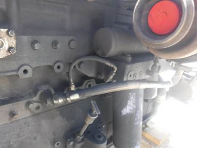
To get straight to the point: the 6.7 Cummins MAP sensor is located on the driver’s side of the engine, mounted directly on the intake manifold, which is also commonly referred to as the intake air horn.3 While the general location is consistent across model years, its specific position and accessibility can vary slightly between generations.
4th Gen Ram (2007.5 – 2018)
On 4th-generation Ram trucks (2007.5-2018), you will find the MAP sensor screwed into the intake manifold on the driver’s side of the engine, just above the valve cover.
For easier identification, look for these specific landmarks:
- It is typically mounted at a 45-degree angle.
- It is positioned just below the Exhaust Gas Recirculation (EGR) valve assembly.
This proximity to the EGR system is a critical detail. The sensor is held in place by a single bolt and has a single electrical connector attached to it.
4th Gen 6.7L Cummins MAP Sensor Location
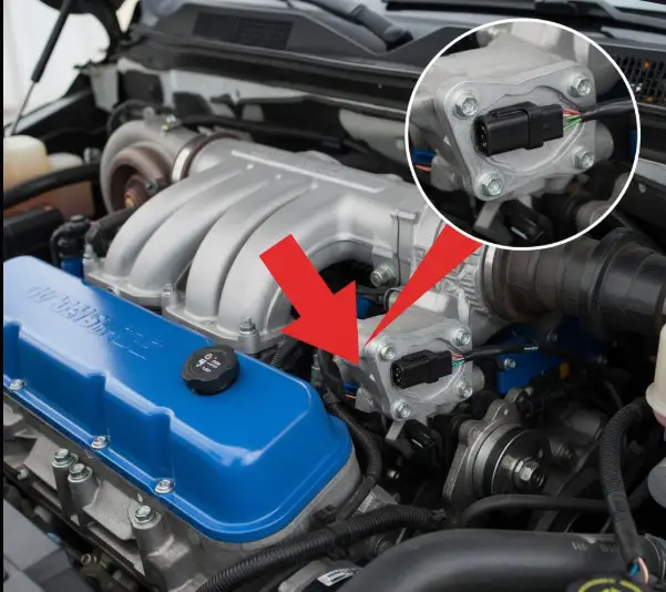
A clear, high-quality photograph of a 4th Gen 6.7L engine bay. A bright red arrow will point directly to the MAP sensor, located on the driver’s side intake manifold below the EGR valve. An inset box will magnify the sensor, highlighting its electrical connector and single mounting bolt for easy identification.
5th Gen Ram (2019 – Present)
For 5th generation Ram trucks (2019-2024+), the MAP sensor remains in the same general area: on the driver’s side of the engine, mounted on the intake manifold. The overall engine bay layout and emissions equipment were updated for the 5th generation, but the sensor’s fundamental position near the intake elbow is unchanged. It is typically identified by its grey electrical connector tab.
5th Gen 6.7L Cummins MAP Sensor Location
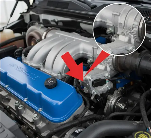
A second, distinct photograph focusing on a 5th Gen 6.7L engine bay. A clear arrow will point to the MAP sensor on the intake manifold. The image will be framed to show its relationship to surrounding components, which differ from the 4th Gen layout.
Why the MAP Sensor’s Location Causes It to Fail
The accessibility of the MAP sensor is convenient for service, but its specific location is also its greatest weakness. The sensor is positioned directly in the path of recirculated exhaust gases from the EGR system. Modern diesel engines route a portion of their exhaust gas back into the intake manifold to lower combustion temperatures and reduce NOx emissions. This gas, however, is not clean; it’s a mixture of fine exhaust soot and oily vapor from the crankcase ventilation system.
This sticky, abrasive mixture flows directly over the MAP sensor. Over time, a layer of soot and oil builds up on the sensor’s delicate electronic components, insulating it and preventing it from taking accurate pressure readings. This contamination is, by far, the most common cause of MAP sensor failure on the 6.7L Cummins.
The prevalence of this issue is so well-known that the aftermarket has responded with a direct solution: MAP Sensor Relocation Kits or Spacers. These kits are designed to move the sensor up and out of the direct flow of the contaminated exhaust stream, allowing it to read the manifold pressure without being constantly coated in soot. The very existence of these products confirms that contamination due to the stock location is the root cause of frequent failures.
| Model Year Range | Generation | Location Description | Key Visual Cues |
| 2007.5 – 2018 | 4th Gen | Driver’s Side, Intake Manifold/Air Horn | Below EGR valve, often at a 45° angle. |
| 2019 – 2024+ | 5th Gen | Driver’s Side, Intake Manifold | Near intake elbow, often has a grey tab on the connector. |
What a MAP Sensor Does and Why Your 6.7 Cummins Needs It
The Manifold Absolute Pressure sensor performs a simple yet profoundly important job: it measures the air pressure inside the engine’s intake manifold. This pressure reading is one of the most critical data points the Engine Control Module (ECM)—the engine’s brain—uses to manage performance.
The ECM takes the pressure reading from the MAP sensor and combines it with data from the Intake Air Temperature (IAT) sensor and the engine speed (RPM) sensor. Together, these inputs allow the ECM to calculate the precise density and mass of the air entering the engine.
Based on this real-time air mass calculation, the ECM makes continuous, split-second adjustments to two vital engine functions:
- Fuel Injection: The ECM determines the exact amount of diesel fuel to inject to achieve the most efficient air-fuel ratio for complete combustion. This is essential for power, fuel economy, and emissions control.
- Ignition Timing: It adjusts the timing of the combustion event to maximize power output and prevent engine-damaging conditions like pre-detonation or “knock” under varying loads.
The MAP sensor also performs a “double duty” role. When you turn the key to the “on” position before starting the engine, there is no vacuum in the intake manifold. During these few seconds, the MAP sensor reads the ambient atmospheric pressure (barometric pressure) and sends this reading to the ECM. This allows the computer to adjust its fuel and timing calculations for your current altitude, ensuring a smooth start whether you’re at sea level or in the mountains.
Top 8 Symptoms of a Bad 6.7 Cummins MAP Sensor
When a MAP sensor begins to fail, it sends inaccurate pressure data to the ECM. The ECM, believing this faulty data is true, makes incorrect adjustments to fuel and timing, leading to a cascade of noticeable performance problems.1 Here are the eight most common symptoms of a bad MAP sensor.
- Check Engine Light (CEL): This is often the first warning sign. The ECM has a pre-programmed set of expected pressure values for given engine speeds and loads. When the MAP sensor’s signal falls outside this range, the ECM logs a Diagnostic Trouble Code (DTC) and illuminates the check engine light.
- Poor Fuel Economy: This is one of the most frequent complaints. If the sensor is contaminated and reads lower pressure (higher vacuum) than is actually present, the ECM will think the engine is under a heavier load and inject more fuel than necessary. This rich fuel mixture directly results in wasted fuel and more frequent trips to the pump.
- Black Smoke from Exhaust: A direct consequence of the rich fuel mixture described above. The excess fuel that the ECM injects cannot be completely burned during combustion. This unburnt fuel is then superheated in the exhaust and expelled from the tailpipe as thick, black soot.
- Rough Idle: The engine may vibrate or struggle to maintain a consistent RPM at idle. This happens because the ECM is trying to stabilize the engine based on erratic and incorrect pressure readings, causing an unstable air-fuel mixture.
- Sluggish Acceleration & Power Loss: Your truck may feel “lazy,” unresponsive, or significantly down on power. Without an accurate measure of engine load from the MAP sensor, the ECM cannot properly match fuel delivery to your throttle input, leading to a noticeable lack of performance.
- Hesitation or Stalling: The engine might stumble or hesitate during acceleration. In more severe cases, the incorrect air-fuel mixture can cause the engine to stall completely when you come to a stop.
- Exhaust Brake Malfunction: The factory exhaust brake on a 6.7L Cummins relies on accurate boost pressure readings to function correctly. If the MAP sensor is faulty and reports incorrect pressure (for example, reading 0 psi of boost while cruising), the exhaust brake may fail to engage or will operate erratically.
- Potential No-Start Condition: In extreme cases of sensor failure, the pressure reading can be so far out of range that the ECM delivers a wildly incorrect air-fuel mixture. This can prevent combustion from occurring altogether, resulting in a crank-no-start condition.
It is important to understand that many of these symptoms are interconnected. A faulty sensor reading causes a rich fuel condition. This single issue then manifests as three distinct symptoms: poor fuel economy (wasted fuel), black smoke (unburnt fuel), and a rough idle (unstable combustion). Recognizing this pattern can help you diagnose a bad MAP sensor with greater confidence.
Decoding the Check Engine Light: Common MAP Sensor DTCs
The most effective way to confirm a MAP sensor issue is to use an OBD-II scanner to read the Diagnostic Trouble Codes (DTCs) stored in the ECM. These codes can point you directly to a fault within the MAP sensor circuit.
The following are the most common fault codes associated with a failing MAP sensor on a 6.7L Cummins engine.
| DTC | Definition | Common Cause |
| P0106 | Manifold Absolute Pressure/Barometric Pressure Circuit Range/Performance Problem | The sensor is providing erratic, intermittent, or illogical readings. This is often caused by heavy soot contamination, a loose electrical connection, or a vacuum leak in the intake. |
| P0107 | Manifold Absolute Pressure/Barometric Pressure Circuit Low Input | The sensor’s signal voltage is below the normal operating range. This typically indicates a short to ground in the wiring, a completely clogged sensor port, or an internally failed sensor. |
| P0108 | Manifold Absolute Pressure/Barometric Pressure Circuit High Input | The sensor’s signal voltage is above the normal operating range. This usually points to an open circuit in the signal or ground wire, or an internally failed sensor. |
| P0069 | Manifold Absolute Pressure – Barometric Pressure Correlation | At key-on, engine-off, the MAP sensor’s reading of atmospheric pressure does not match the expected value stored in the ECM. This strongly suggests a faulty sensor. |
| P0652 | Sensor Reference Voltage 2 Low | This code indicates a problem with the 5-volt reference circuit that the ECM provides to several sensors, including the MAP sensor. Diagnostic procedures for this code often involve unplugging the MAP sensor to see if the short circuit is resolved, which would isolate the MAP sensor as the cause. |
How to Test a 6.7 Cummins MAP Sensor: A Step-by-Step Diagnostic Guide
Before replacing the sensor, it’s wise to perform a few simple tests to confirm it’s the source of the problem. You can do this with basic tools, primarily a digital multimeter.
Safety First: Before unplugging any sensors or performing electrical tests, always disconnect both negative battery terminals. This prevents the risk of electrical shock or accidental short circuits that could damage sensitive electronics.22
The Visual Inspection (The 60-Second Check)
Start with a thorough visual inspection of the sensor and its surroundings. Engine bays are harsh environments, and failures are often caused by physical damage.
- Inspect the Wiring: Carefully examine the wiring harness leading to the MAP sensor. Look for any signs of cracking, melting from excessive heat, or chafing where it might be rubbing against another component.
- Check the Connector: Unplug the electrical connector and inspect the pins on both the sensor and the harness side. Look for any green or white corrosion, bent pins, or a loose fit. A poor connection can cause the same symptoms as a bad sensor.
Testing with a Multimeter (The Definitive Test)
This test will measure the sensor’s voltage output to determine if it’s responding correctly to changes in pressure. For this, you will need a digital multimeter and a set of back-probe pins or T-pins to access the wires without damaging the connector’s weather seals.
MAP Sensor Wiring Diagram
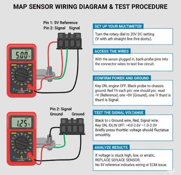
A simple, clear diagram illustrating the 3-pin MAP sensor connector. Each pin will be labeled: “Pin 1: 5V Reference,” “Pin 2: Signal,” and “Pin 3: Ground.” The diagram will show the correct placement of the red and black multimeter probes for testing the reference voltage and the signal voltage.
- Set Up Your Multimeter: Turn the rotary dial on your digital multimeter to the 20V DC setting, which is usually indicated by a ‘V’ with a straight line and three dots.
- Access the Wires: With the sensor still plugged in and the batteries reconnected, carefully insert back-probe pins into the back of the connector for each of the three wires. This allows you to take readings while the circuit is live.
- Confirm Power and Ground: Turn the ignition key to the “ON” position, but do not start the engine.
- Connect the black probe of your multimeter to a solid chassis ground (like the alternator bracket or a bolt on the engine block).
- Touch the red probe to each of the three back-probe pins in turn.
- One wire should read a steady 5 volts (this is the reference voltage from the ECM). One wire should read 0 volts (this is the ground). The third is your signal wire.
- If you do not have a 5-volt reference, the problem lies in the wiring or the ECM, not the sensor itself.
- Test the Signal Voltage: Connect the black multimeter probe to the ground wire’s back-probe pin and the red probe to the signal wire’s back-probe pin.
- With the key on, engine off, the voltage should be high, typically around 4.6 volts. This represents atmospheric pressure (zero vacuum).
- Now, start the engine. As the engine idles, it creates a vacuum in the intake manifold. The voltage should immediately drop to between 1.0 and 2.0 volts.
- Lightly press and release the throttle. You should see the voltage fluctuate smoothly and instantly with the change in engine RPM.
- Analyze the Results: If the voltage is stuck high (e.g., 4.6V) even when the engine is running, is stuck low, or does not change smoothly with the throttle, the MAP sensor is faulty and must be replaced.
| Condition | Vacuum (inHg) | Approximate Signal Voltage (DCV) |
| Key On, Engine Off | 0 | ~$4.6$ V |
| Engine Idling | ~$15-20$ | ~$1.5$ V |
| Light Throttle | ~$5-10$ | ~$3.0$ V |
Cleaning a Dirty MAP Sensor: Can You Save It?
Since soot and oil contamination is the number one cause of MAP sensor failure, cleaning the sensor is a highly effective and inexpensive first step that can often restore its function and save you the cost of a new part.
The Right Tools for the Job
To clean the sensor safely, you will need:
- A socket or wrench to remove the sensor’s mounting bolt.
- A can of Mass Air Flow (MAF) Sensor Cleaner or a dedicated Electronic Parts Cleaner. These cleaners are specifically formulated to be safe on sensitive electronics and evaporate without leaving a residue.
CRITICAL WARNING: NEVER use brake cleaner, carburetor cleaner, degreasers, or compressed air on a MAP sensor. These chemicals are far too aggressive and will permanently damage the delicate internal components of the sensor.1
How to Safely Clean the Sensor (Step-by-Step)
- Disconnect the battery terminals.
- Unplug the electrical connector from the MAP sensor.
- Remove the single bolt holding the sensor in place.
- Gently twist and pull the sensor straight out of the intake manifold. It may be snug due to the O-ring seal.
- Hold the sensor with the sensing element pointing downwards to allow debris to fall out.
- Liberally spray the inside and outside of the sensor tip with the MAF or electronics cleaner. The goal is to chemically dissolve and wash away the black soot buildup. Do this for 10-15 seconds.
- DO NOT SCRUB, WIPE, OR TOUCH THE SENSOR ELEMENT. It is extremely fragile. Let the chemical spray do all the work.
- Gently shake out any excess cleaner and set the sensor aside to air dry completely for at least 30 minutes. Do not attempt to reinstall it while it is still wet.
Don’t Forget to Clean the Port
A perfectly clean sensor will not work if the hole it sits in is clogged with carbon. The port in the intake manifold where the sensor reads pressure is often just as contaminated as the sensor itself.
- With the sensor removed, inspect the port in the intake manifold. It is common to find it heavily restricted with a thick layer of hard carbon buildup.
- Hold the nozzle of a shop vacuum directly over the hole to create suction.
- Carefully use a small, long-handled pick or a thin screwdriver to gently scrape and break up the carbon inside the port. The vacuum will suck out the loose debris, preventing it from falling down into the engine’s intake.
- Once the port is clear, you can reinstall your clean, dry MAP sensor, reconnect the electrical connector, and reconnect the batteries.
6.7 Cummins MAP Sensor Replacement Cost
If testing confirms your sensor is bad or cleaning doesn’t solve the problem, replacement is the next step. This is a very straightforward job that can be completed in under 30 minutes, making it an excellent DIY task. The cost will vary depending on whether you do the work yourself and the type of part you choose.
| Cost Component | DIY Cost | Professional Repair Cost |
| Aftermarket MAP Sensor | $60 – $95 | (Included in Parts) |
| OEM Cummins/Mopar Sensor | $95 – $120 | $178 – $257 (Shop Markup) |
| Labor | $0 | $42 – $62 (Approx. 0.5 hr) |
| Total Estimated Cost | $60 – $120 | $220 – $319 33 |
As the table shows, tackling this job yourself can save you a significant amount of money, with the only cost being the part itself. For more information on maintaining your truck, see our guides on regular Cummins maintenance schedules.
Finding the Right Part: 6.7 Cummins MAP Sensor Part Numbers
Using the correct part number is essential for ensuring proper fit and function. Over the years, Cummins and Mopar have updated and superseded the part numbers for the MAP sensor. When purchasing a replacement, it is always best to acquire the latest revised part number, as it may include improvements to durability or accuracy.
For example, for the 2007.5-2018 model years, the original part number 2897333 has been replaced by the newer, updated part number 5698455. While a part with the old number will still work, the new number represents the most current version from the manufacturer.
| Model Year Range | OEM Cummins Part # | Superseded Part #(s) | OEM Mopar Part # |
| 2007.5 – 2018 | 5698455 (Latest) | 2897333, 4921322, 4903286 | 68002434AA, 68282012AA |
| 2019 – 2024 | 5698456 or 2897334NX | (N/A) | 68453737AA |
For highly modified trucks running extreme levels of boost, aftermarket companies offer high-pressure sensors (e.g., 10-bar sensors). These are specialized components for performance applications and should not be used on a stock or lightly modified vehicle.
To learn about the common locations for other critical engine sensors, check out our other guides. For more information on testing procedures, technical resources like Fluke offer excellent guides. You can source OEM parts from suppliers like(https://www.delphiautoparts.com/resource-center/article/making-sense-of-your-sensors-map-sensor) or directly from the(https://store.mopar.com/oem-parts/mopar-map-sensor-68453737aa).
Frequently Asked Questions (FAQs)
Can I drive my Cummins with a bad MAP sensor?
While the truck may still run, it is not recommended. Driving with a faulty MAP sensor will result in poor engine performance, terrible fuel economy, and increased emissions. In some cases, the engine can surge unpredictably, which can be a safety hazard. Long-term operation in a rich condition can also lead to premature clogging of the Diesel Particulate Filter (DPF) and other emissions system components.
How often should a MAP sensor be replaced?
There is no manufacturer-specified replacement interval for the MAP sensor; it is considered a “replace when failed” component. However, given its tendency to become contaminated and its relatively low cost, many owners choose to proactively clean it every 30,000-50,000 miles or replace it as a preventative maintenance item around 60,000 miles to avoid being stranded by a failure.
Will a bad MAP sensor cause my exhaust brake to stop working?
Yes, a faulty MAP sensor is a common cause of exhaust brake malfunction. The ECM requires an accurate boost pressure reading from the MAP sensor to properly command the exhaust brake. If the sensor is sending incorrect data (like reading zero boost when the truck is cruising under load), the exhaust brake will not engage or will perform erratically.
What is a MAP sensor relocation kit?
A MAP sensor relocation kit is an aftermarket solution designed to solve the chronic contamination issue. It typically consists of a spacer or a small tube that moves the sensor out of the direct path of the oily soot coming from the EGR system. This allows the sensor to read manifold pressure accurately while staying much cleaner, significantly improving its long-term reliability.
Can a bad MAP sensor cause transmission problems?
Indirectly, it can. The MAP sensor does not directly control the transmission. However, the ECM shares engine load information with the Transmission Control Module (TCM). If the MAP sensor is providing false load data, the engine’s performance will be erratic. This can cause the TCM to command harsh shifts, shift at inappropriate times, or hunt for gears, making it seem like there is a transmission problem when the root cause is actually the engine sensor. Resolving the MAP sensor issue often clears up these perceived transmission symptoms.