7.3 Powerstroke Sensor Location Diagram (1994.5-2003) – The Definitive Guide
A search for a “7.3 powerstroke sensor location diagram” typically means a repair or diagnosis is underway. Simply knowing a sensor’s location is only half the battle. The root of the search is almost always a specific, frustrating drivability problem: a truck that cranks but won’t start, a rough, surging idle , a sudden loss of power, or plummeting fuel economy.
This guide provides a comprehensive set of diagrams and location descriptions. More importantly, it functions as a complete diagnostic tool. The key to diagnosing this legendary engine is understanding its two distinct generations:
- OBS (Old Body Style): 1994.5–1997 F-Series trucks.
- Super Duty (SD): 1999–2003 F-Series, Excursion, and E-Series vans.
These two generations, while sharing the 7.3L displacement, use different sensor part numbers, different locations for key sensors , and even fundamentally different technologies, such as the accelerator pedal. This guide will meticulously differentiate between them, providing the location, function, symptoms, and testing procedures for every critical sensor to fix the problem correctly the first time.
The 7.3L Powerstroke Sensor Guide
A Visual Guide to Locations & Troubleshooting
Why Sensors are Critical on the 7.3L
The 7.3L Powerstroke (1994.5-2003) uses a unique Hydraulically actuated Electronic Unit Injection (HEUI) system. Unlike other diesels, it uses high-pressure engine oil (up to 3,000+ PSI) to fire the injectors.
This system relies on a network of critical sensors to tell the computer (PCM) exactly what to do. A single bad sensor can prevent the engine from starting, kill performance, or cause rough running. Knowing where they are is the first step to diagnosis.
A Legendary Engine
units were produced, making it one of the most popular diesel engines ever. Many are still on the road today thanks to their durability.
Common 7.3L Sensor Failure Points
Based on owner reports, some sensors are far more likely to fail (or clog) than others. The Camshaft Position Sensor (CMP) is the most notorious.
Sensor System Breakdown
Sensors can be grouped by the primary system they monitor. The Injection and Turbo/Air systems are the most sensor-heavy, critical for performance.
Sensor Location Diagram (Conceptual Groups)
Use this as your “diagram.” Instead of a cluttered image, these cards group sensors by their physical location on the engine, making them easier to find.
1. Front of Engine
- CMP (Camshaft Position Sensor): The most critical sensor. Located on the top-front of the engine block, passenger side, reading a gear behind the harmonic balancer.
- ECT (Engine Coolant Temp): Near the thermostat housing, typically on the water pump or front cover.
- EBP (Exhaust Back Pressure) Tube: The sensor itself is often on a bracket, but its tube connects to the front of the driver’s side exhaust manifold. This tube clogs frequently.
2. Engine Valley (Top)
- ICP (Injection Control Pressure) Sensor: Measures high-pressure oil. On early models (94-95), it’s on the driver’s side cylinder head. On later models, it’s in the HPOP housing at the front of the valley.
- IPR (Injection Pressure Regulator): An actuator, but key to the system. Located on the back of the High-Pressure Oil Pump (HPOP) at the front of the valley.
- IAT (Intake Air Temp): Screwed into the intake manifold/plenum, typically in the “spider” (intake runners).
3. Driver’s Side (Block)
- EOT (Engine Oil Temp): Located on the driver’s side of the engine block, near the oil filter housing/cooler assembly.
- CPS (Crankshaft Position Sensor): *Note: The 7.3L primarily uses the CMP.* A CKP was present on some models but is not the primary sensor for engine operation.
4. Firewall / Intake / Cab
- MAP (Manifold Absolute Pressure): Measures turbo boost. On Super Duty models, it’s on the firewall (passenger side). On OBS models, it’s often on the passenger side fender. A hose runs from it to the intake manifold.
- APP (Accelerator Pedal Position): The “drive-by-wire” pedal assembly. Located inside the cab, attached to the accelerator pedal.
5. Drivetrain / Other
- VSS (Vehicle Speed Sensor): Affects shifting. On 2WD/some 4x4s, it’s on the transmission output shaft. On many models, it’s located on the top of the rear axle differential.
- EBP Sensor (Location): The sensor itself (not the tube) is often on a bracket near the HPOP reservoir at the front of the engine.
Common Symptoms & Potential Sensors
Engine Won’t Start?
↓
First, check the tachometer when cranking. If it doesn’t move, it’s almost certainly the CMP.
Low Power / No Boost?
↓
The engine feels lazy and won’t build boost, or you see excessive smoke.
Rough Idle / Stalling?
↓
Engine stumbles, idles poorly, or stalls when coming to a stop.
7.3 Powerstroke Sensor Location Master Table (OBS vs. Super Duty)
This master table provides a quick, skimmable reference for the location of all critical sensors and actuators. Specific diagnostic details for each component follow in the sections below.
| Sensor / Component | 1994.5-1997 (OBS) Location | 1999-2003 (Super Duty) Location | Primary Function |
| Camshaft Position Sensor (CPS) | Front of engine, driver’s side, ~11:00 position, above crankshaft damper. | (Same Location) | Tells PCM engine speed (RPM) & position. Critical for starting. |
| Injection Control Pressure (ICP) Sensor | Driver’s side cylinder head, near the front, screws into the high-pressure oil rail. | (Same Location, but sensor/pigtail may differ) | Measures high-pressure oil in the HEUI system. |
| Injection Pressure Regulator (IPR) Valve | Back of the High-Pressure Oil Pump (HPOP), deep in the engine valley, under the fuel filter. | (Same Location) | Actuator that controls HPOP pressure. |
| Exhaust Back Pressure (EBP) Sensor | Back of the HPOP reservoir. | Front of the HPOP reservoir. | Measures exhaust pressure to control the EBPV for warm-up. |
| Manifold Absolute Pressure (MAP) Sensor | Passenger side firewall, connected via hose. | Passenger side firewall or HVAC box, connected via hose. | Measures intake manifold pressure (boost). |
| Engine Oil Temperature (EOT) Sensor | Top of the HPOP reservoir. | (Same Location) | Critical PCM sensor for fuel timing, glow plugs, and idle. |
| Accelerator Pedal Position (APPS / TPS) | On the throttle pedal assembly under the hood, connected by a throttle cable. | Integrated into the accelerator pedal assembly inside the cab. (Drive-by-wire) | Tells PCM the driver’s throttle request. |
| Intake Air Temperature (IAT) Sensor | In the air cleaner intake assembly/box. | (Same Location) | Measures incoming air temperature for air-fuel mixture. |
| Engine Oil Pressure (EOP) Sensor | Driver’s side of the engine block, near the oil filter housing. | (Same Location) | Feeds the dashboard gauge only. Not used by PCM. |
| Engine Coolant Temperature (ECT) Sensor | Screwed into the water pump / thermostat housing. | (Same Location) | Feeds the dashboard gauge only. Not used by PCM. |
Part 1: The “Crank, No-Start” Triangle (CPS, ICP, IPR)
The most common and alarming failure on a 7.3L Powerstroke is the “crank, no-start” condition. Unlike a gasoline engine, the 7.3L uses a Hydraulic Electronic Unit Injection (HEUI) system, which uses high-pressure engine oil (up to 3,000+ PSI) to atomize and inject fuel.
This system relies on a closed-loop “triangle” of three components to start:
- When the key is turned, the Camshaft Position Sensor (CPS) must send a valid RPM signal to the Powertrain Control Module (PCM).
- The PCM, confirming the engine is spinning, commands the Injection Pressure Regulator (IPR) Valve to close, telling the High-Pressure Oil Pump (HPOP) to build pressure.
- The Injection Control Pressure (ICP) Sensor monitors this pressure.
- The PCM will only signal the Injector Driver Module (IDM) to fire the injectors after it receives a valid CPS signal and the ICP sensor reports a minimum of 500 PSI of oil pressure.
A failure in any one of these three components, or their wiring, breaks this operational chain and results in a “crank, no-start” condition. Randomly replacing these parts is expensive. A simple, three-step diagnostic process can pinpoint the culprit:
- Step 1: While cranking the engine, watch the tachometer on the dashboard. If the needle does not move or bounces erratically, the CPS has failed.
- Step 2: If the tachometer does move, locate and unplug the electrical connector for the ICP sensor. Try to start the engine. If it fires up (it will run rough), the ICP sensor is bad.
- Step 3: If the tach works and the ICP unplug test fails, the problem is most likely the IPR valve (or its O-rings/wiring) or a weak HPOP.
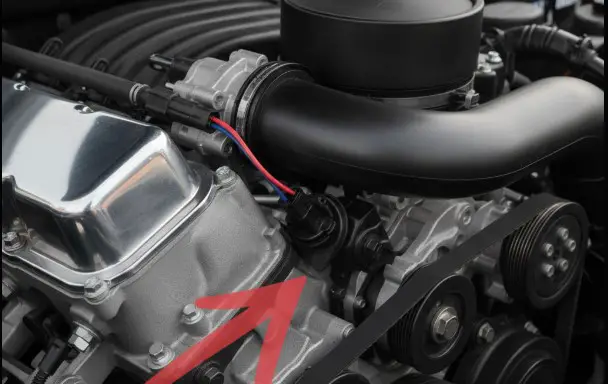
1. Camshaft Position Sensor (CPS) / (CMP)
- Function: The Camshaft Position Sensor (CPS), also known as the CMP sensor, is a Hall Effect sensor that reads a 24-window wheel on the camshaft. This is the PCM’s primary input for engine speed (RPM) and piston position, which is essential for correct injector timing.
- Location (All Years 94.5-03): The CPS is located on the front of the engine block on the driver’s side. It is positioned at approximately the 11:00 o’clock position, just above the crankshaft damper (main pulley). It is held in by a single 10mm bolt and is notoriously difficult to access without the correct wrench or socket.
“
- Symptoms of Failure:
- Classic Crank, No-Start: The engine turns over but will not fire.
- No Tachometer: The tachometer needle on the dashboard does not move at all while cranking. This is the definitive symptom.
- Sudden Stall: The engine dies abruptly while driving, as if the key were turned off. This can be intermittent or happen when hitting a bump.
- DTCs: P0340 (CMP Sensor Malfunction), P0344 (CMP Circuit Intermittent).
- OEM Part Numbers (A Critical Detail): Not all CPS sensors are equal. Using aftermarket sensors is a common source of repeat failures.
- Original (Black): P/N F7TZ-12K073-A. This original black sensor is widely considered the most reliable.
- Recall (Grey): P/N F7TZ-12K073-B. This was Ford’s replacement sensor from a recall. It is known to cause a noticeable rough idle and, in some cases, trigger false P0284 codes (Injector #8 misdiagnosis) during a cylinder contribution test.
- OBS (Dark Grey): P/N F4TZ-12K073-C. This is the OEM sensor for 1995-1997 trucks. Many 1999-2003 owners use this sensor as an “upgrade” over the grey recall sensor, reporting a smoother idle.
- Actionable Advice: It is highly recommended to use only OEM Motorcraft or International-branded sensors and to carry a known-good spare in the glovebox.
2. Injection Control Pressure (ICP) Sensor
- Function: This is the pressure gauge for the HEUI system. It constantly monitors the high-pressure oil (from 500 to 3,000+ PSI) and sends this reading to the PCM. The PCM uses this data to make adjustments to the IPR valve.
- Location (All Years 94.5-03): The ICP sensor is located on the driver’s side cylinder head, near the front of the engine.3 It screws directly into the high-pressure oil rail. It is typically one of the easier sensors to access.
“
- Symptoms of Failure:
- Crank, No-Start: This is the most common symptom. If the sensor fails and reads 0 PSI, the PCM will not fire the injectors.
- Rough Idle & Stalling: The engine idles erratically, surges, or stalls when coming to a stop.
- Hesitation: Poor throttle response or lack of power.
- DTCs: P1211 (ICP Pressure Above/Below Desired), P1280 (ICP Circuit Out of Range).
- How to Test (The “Unplug Test” & Visual Check):
- Visual: Disconnect the electrical pigtail from the sensor. Look inside the connector. If it is full of engine oil, the sensor’s internal seal has failed, and it must be replaced.
- Unplug Test: Disconnect the ICP sensor harness and attempt to start the engine. If the truck starts and idles (it will be loud and rough), the PCM has recognized the missing signal and is using a default (failsafe) map. This 100% confirms the ICP sensor is faulty.
- Scan Tool: With a diagnostic scanner, ICP pressure at idle should be between 500-700 PSI. With a multimeter, the signal wire should read approximately 0.8-1.2 volts at idle.
3. Injection Pressure Regulator (IPR) Valve
- Function: The IPR is not a sensor; it is an actuator. It is an electromagnetic valve that the PCM commands to either build or bleed off oil pressure from the HPOP. It works with the ICP sensor to regulate the high-pressure oil system.
- Location (All Years 94.5-03): This is one of the most difficult components to access. It is located on the back of the High-Pressure Oil Pump (HPOP), deep in the engine valley, directly underneath the fuel filter housing. The fuel filter housing must be removed to replace it.
“
- Symptoms of Failure:
- Rough/Unstable Idle: The idle surges or is extremely erratic.
- Stalling: The engine stalls when the throttle is released or when coming to a stop.
- Hot No-Start: The truck starts fine when cold but will crank without starting after it has reached operating temperature. This is often due to failing O-rings on the IPR.
- Loss of Power: The truck feels weak under load.
- Noise: A loud grinding or “buzzing” sound may come from the HPOP area.
- How to Test: The IPR is best diagnosed by elimination (if the CPS and ICP are confirmed good). The valve itself can be tested with a high-end scan tool by commanding a specific duty cycle. Often, the O-rings on the IPR valve fail, not the valve itself. Replacing these O-rings is a common, inexpensive repair. Reputable diesel shops, like(https://www.riffraffdiesel.com/ipr-injection-pressure-regulator-96-03/), are good sources for replacement parts.31
Part 2: Performance, Boost & Fuel Economy Sensors
If the truck starts and runs, but suffers from low power, excessive black smoke, or poor fuel mileage, the issue often lies with the sensors that manage the air-fuel mixture and turbocharger.
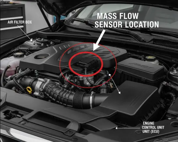
4. Manifold Absolute Pressure (MAP) Sensor
- Function: The MAP sensor measures the pressure (boost) in the intake manifold after the turbocharger. The PCM compares this boost reading to the barometric pressure to calculate engine load and inject the correct amount of fuel.
- Location (All Years 94.5-03): This sensor is not located on the engine block. It is mounted on the passenger side of the firewall, sometimes inside the HVAC box, and is easily accessible.
- The Clogged Tube Connection: The MAP sensor is connected to the intake “spider” (the intake plenum on top of the engine) by a small-diameter rubber hose. This hose is a primary failure point. If it cracks, splits, or becomes clogged with oil and soot, the sensor cannot read boost. The PCM, thinking the turbo is not working, will command a “de-fuel” condition to prevent damage, making the truck feel extremely sluggish or gutless. Always inspect this hose before replacing the sensor.
- Symptoms of Failure:
- Poor fuel economy.
- Sluggish acceleration and significant loss of power.
- Excessive black smoke (a rich condition if the sensor is faulty).
- Rough idle.
- DTCs: P0236 (Turbo Boost Sensor A), P1247 (Boost Pressure Low), P1248 (Boost Pressure Not Detected).
- Part Number Difference:
- OBS (94-97): F4TZ-9F479-A
- Super Duty (99-03): F8UZ-9F479-BA
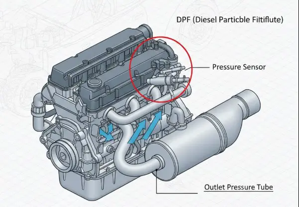
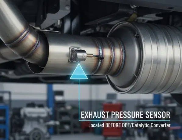
5. Exhaust Back Pressure (EBP) Sensor
- Function: This sensor measures exhaust pressure in the manifold before the turbocharger. Its only job is to provide data to the PCM to control the Exhaust Back Pressure Valve (EBPV), a butterfly valve in the turbo pedestal that closes during cold weather to help the engine warm up faster.
- Location (CRITICAL Generational Difference):
- 1994.5-1997 (OBS): Located on the BACK of the HPOP reservoir, deep in the engine valley.
- 1999-2003 (Super Duty): Located on the FRONT of the HPOP reservoir, making it much easier to access.
“
- The Clogged Tube Failure: The EBP sensor itself rarely fails. The most common problem by far is that the metal tube running from the passenger-side exhaust manifold up to the sensor becomes completely clogged with hard-packed soot. When clogged, the sensor simply reads atmospheric pressure, confusing the PCM.
- How to Fix: The most common repair is free. Remove the sensor and the tube. Clean the sensor’s orifice carefully and use a stiff wire or drill bit to manually ream out the soot from the metal tube until it is clear. This “free fix” restores sensor function 90% of the time.(https://www.riffraffdiesel.com/blog/73l-powerstroke-exhaust-back-pressure-sensor-diagnosis/) provides an excellent overview.
- Symptoms of Failure (Clogged Tube):
- Noticeably reduced MPG, as the PCM may alter fueling tables.
- Sluggishness or hesitation when accelerating.
- Smoky starts in cold weather (as the EBPV isn’t functioning).
- DTCs: P0470 (EBP Sensor Malfunction), P0471 (EBP Range/Performance).
6. Intake Air Temperature (IAT) / Manifold Air Temperature (MAT) Sensor
- Function: This is a simple thermistor that measures the temperature of the air entering the engine, allowing the PCM to adjust fuel timing and quantity based on air density.
- Location (All Years 94.5-03): Located in the intake air system, typically found on the air filter housing (air cleaner assembly). On the 7.3L, this sensor is also commonly referred to as the Manifold Air Temperature (MAT) sensor.
- Symptoms of Failure:
- Poor engine performance and rough idle.
- Hard starting.
- Excessive white or black smoke.
- Reduced fuel economy.
- DTCs: P0112 (IAT Circuit Low), P0113 (IAT Circuit High).
7. Barometric Pressure (BARO) Sensor
- The “Hidden” Sensor: There is no standalone BARO sensor on a 7.3L Powerstroke. A technician looking for one will not find it.
- Function: The MAP sensor performs a dual role. At “Key On, Engine Off” (KOEO), the intake manifold is at atmospheric pressure. The PCM takes a reading from the MAP sensor at this moment and stores that value as its baseline Barometric Pressure reading. When the engine starts, the PCM compares the live MAP sensor reading (boost) against this saved BARO value to determine engine load.
- Implication: BARO-related DTCs (like P0069, P0106, or P0107) do not indicate a failure of a “BARO sensor,” but rather a problem with the MAP sensor, its wiring, or its (potentially cracked) hose.
Part 3: Driver Input & Gauge Sensors (What You See vs. What the PCM Sees)
A common and expensive diagnostic mistake is confusing the sensors that feed the dashboard gauges with the sensors that the PCM uses to run the engine. On the 7.3L, they are almost entirely separate.
8. Accelerator Pedal Position Sensor (APPS) / Throttle Position Sensor (TPS)
- Mechanical vs. Electronic (A Fundamental Difference): The way the driver’s throttle input is read is completely different between the two 7.3L generations.
- 1994.5-1997 (OBS): These trucks use a mechanical throttle cable. The sensor is a Throttle Position Sensor (TPS) located under the hood, mounted on the accelerator pedal assembly where the cable connects.
- 1999-2003 (Super Duty): These trucks are drive-by-wire. There is no cable. The sensor is an Accelerator Pedal Position Sensor (APPS) integrated directly into the accelerator pedal assembly inside the cab.
“
- Symptoms of Failure:
- “Dead pedal” or no throttle response.
- Erratic engine response (surging or falling flat).
- Engine stuck at a high idle speed.
- Vehicle goes into “limp mode,” limiting power.
- DTCs: P0220, P0221 (Throttle/Pedal Position Sensor/Switch).
9. Engine Oil Temperature (EOT) Sensor
- The PCM’s REAL Temperature Sensor: This is one of the most misunderstood sensors. The PCM does not use the coolant temperature sensor for its logic. It only uses the Engine Oil Temperature (EOT) sensor.
- Function: The EOT sensor signal is critical for all cold-weather operations. The PCM uses it to control:
- Glow Plug Control: Determines the “Wait to Start” light duration.
- Fuel Timing & Quantity: Enrichens the mixture for cold starts.
- Idle Speed: Engages the high-idle (up to 950 RPM) when the oil is below 158°F.
- Implication: If a 7.3L has hard cold starts, the glow plugs don’t stay on long enough, or it runs poorly when cold, the EOT sensor is the likely culprit, not the ECT sensor.
- Location (All Years 94.5-03): Screwed into the top of the HPOP reservoir, located in the engine valley.
- Symptoms of Failure:
- Difficult cold starts.
- Poor cold-weather drivability.
- Incorrect glow plug relay operation.
- DTCs: P0197 (EOT Sensor Circuit Low), P0198 (EOT Circuit High).
10. Engine Oil Pressure (EOP) Sensor
- The “Dummy” Gauge Sensor: This sensor has only one function: to operate the oil pressure gauge on the dashboard.
- Function: This sensor is a simple switch. It is not used by the PCM for any engine management or fueling logic. The PCM only cares about the high-pressure oil system, which is monitored by the ICP sensor.
- Implication: A rough-running engine, no-start condition, or loss of power is never caused by this sensor. Its only failure symptom is the dashboard gauge reading zero, pegged high, or flickering.
- Location (All Years 94.5-03): Located on the driver’s side of the engine block, near the oil filter housing.
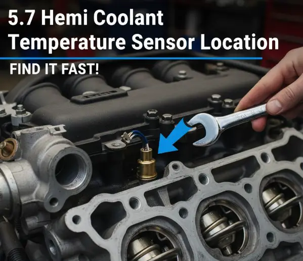
11. Engine Coolant Temperature (ECT) Sensor
- The “Dummy” Gauge Sensor (Part 2): Like the EOP sensor, this component is for the driver’s information only.
- Function: This sensor’s sole purpose is to send a temperature reading to the coolant temperature gauge on the dashboard.
- The Critical Fact: There is no PCM input for ECT on any 7.3L Powerstroke. The PCM uses the EOT sensor for all temperature-based calculations.
- Implication: Replacing this sensor will not fix any drivability, glow plug, or cold-start problem. It will only fix a faulty dash gauge.
- Location (All Years 94.5-03): Screwed into the water pump housing, near the thermostat.
7.3 Powerstroke Sensor Troubleshooting: FAQs
Q: What sensor causes a 7.3 Powerstroke to not start?
A: The three most common causes are in the “No-Start Triangle.”) The Camshaft Position Sensor (CPS) is the most common failure; check for a dead tachometer while cranking.1 2) The Injection Control Pressure (ICP) Sensor; the PCM needs to see 500 PSI to start. Unplug it to see if the truck fires on a default map.) The Injection Pressure Regulator (IPR) Valve; if it is stuck open or its O-rings are bad, it cannot build pressure.
Q: Where is the ICP sensor on a 7.3 Powerstroke?
A: On all 1994.5-2003 models, the ICP sensor is located on the driver’s side cylinder head, near the front of the engine. It screws into the high-pressure oil rail.
Q: Where is the CPS sensor on a 7.3 Powerstroke?
A: On all models, the CPS is at the front of the engine on the driver’s side. It is at the 11:00 o’clock position, just above the main crankshaft pulley (harmonic damper).
Q: How do I test a 7.3L ICP sensor?
A: First, visually inspect the electrical connector for oil; if oil is present, the sensor is bad. Second, perform the “unplug test”: disconnect the sensor and try to start the engine. If it starts, the sensor is bad. Finally, a scan tool should read 500-700 PSI at idle.
Q: What sensors control the turbo on a 7.3 Powerstroke?
A: Three components primarily control the turbo system. The MAP sensor measures boost output 5, the EBP sensor measures back pressure to control the warm-up valve (EBPV) 6, and the Wastegate Control Solenoid (on Super Duty models) controls the wastegate to limit maximum boost.
Q: How many coolant sensors does a 7.3 Powerstroke have?
A: This is a common point of confusion. The 7.3L has two temperature sensors. 1) The Engine Coolant Temperature (ECT) Sensor is on the water pump and only runs the dashboard gauge.) The Engine Oil Temperature (EOT) Sensor is on the HPOP reservoir and is used by the PCM for glow plugs and cold-start fueling. If you have a cold-start problem, test the EOT sensor.
Q: Where is the MAP sensor on a 1999-2003 7.3 Powerstroke?
A: The MAP sensor is not on the engine. It is located on the passenger side firewall, sometimes inside the HVAC box, and is connected to the intake by a small rubber hose.
Q: Where is the EBP sensor on a 1997 7.3 Powerstroke?
A: On 1994.5-1997 OBS (Old Body Style) trucks, the EBP sensor is located on the back of the HPOP reservoir in the engine valley, making it difficult to reach.6 This is different from the 1999-2003 Super Duty, where it is on the front.
Conclusion: Diagnosis Before Dollars
The 7.3L Powerstroke’s longevity is legendary, but its operation depends on a precise, closed-loop electronic and hydraulic system. Before spending money on new parts, a methodical diagnosis is essential.
- For no-start issues, always follow the diagnostic hierarchy: check the CPS via the tachometer, then perform the ICP unplug test.
- For low-power issues, always check the “plumbing” before replacing a sensor. A clogged EBP tube or a cracked MAP sensor hose are the most common and cheapest-to-fix culprits.
- Do not confuse the dashboard gauge sensors (ECT, EOP) with the critical PCM sensors (EOT, ICP). A poor-running engine will not be fixed by replacing a gauge sender.
Finally, the quality of these sensors matters immensely. Aftermarket sensors, especially for the critical CPS and ICP, are notorious for premature failure. Using OEM-grade (Motorcraft or International) parts is the most reliable way to ensure a lasting repair.
Now that you’ve mastered the 7.3L’s sensors, learn about other 7.3 Powerstroke Common Problems and how to fix them, or explore our complete guide to 7.3 Powerstroke Upgrades for reliability and power. For official diagnostic code information, authoritative sources like(https://boschdiagnostics.com/sites/default/files/2025-01/OBD%201350%20User%20Manual.pdf) are invaluable.