Cummins ISX Engine Speed Sensor Location: Complete Guide & Troubleshooting
When your Cummins ISX-powered rig suddenly throws a check engine light and starts running rough at highway speeds, knowing exactly where to find those critical engine speed sensors can make the difference between a quick roadside fix and an expensive tow. After spending nearly two decades working on these powerplants, I’ve learned that locating the Cummins ISX engine speed sensor is often the first step in diagnosing timing-related issues. This guide will walk you through exactly where to find these sensors, how to replace them, and what to watch for when troubleshooting sensor-related problems.
Understanding Cummins ISX Engine Speed Sensors
Before diving into specific locations, let’s understand what we’re looking for and why these sensors matter so much to your truck’s performance.
What Are Engine Speed Sensors and Why Do They Matter?
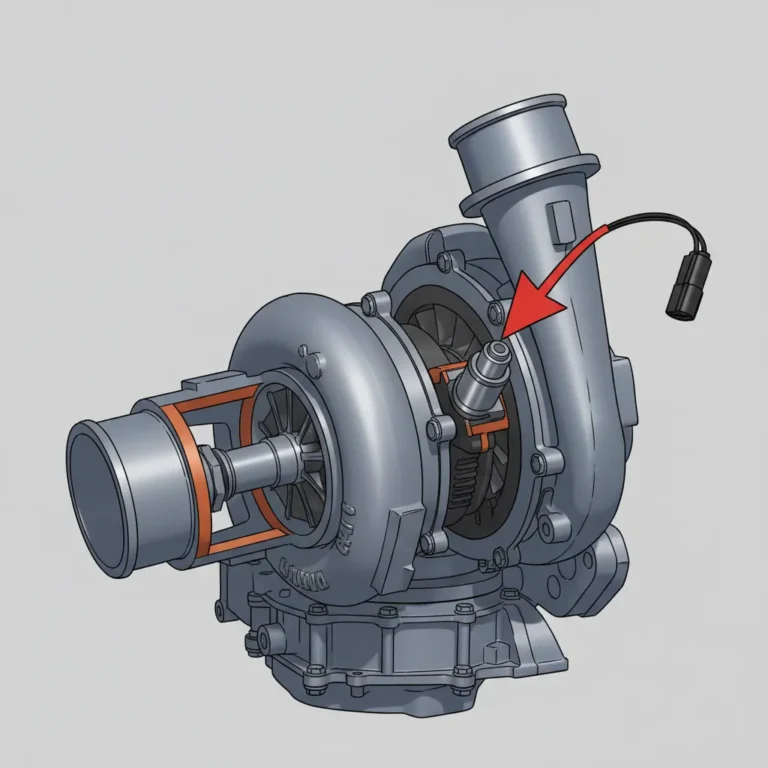
Engine speed sensors are essentially sophisticated magnetic pickups that monitor the rotation of key engine components. The Cummins ISX uses two primary speed sensors:
- Crankshaft Position Sensor (CPS) – Monitors the position and speed of the crankshaft
- Camshaft Position Sensor (CamPS) – Tracks the position and speed of the camshaft
Together, these sensors provide crucial timing information that the Engine Control Module (ECM) uses to:
- Determine precise fuel injection timing
- Control variable geometry turbocharger position
- Manage engine braking functions
- Monitor for dangerous operating conditions
- Regulate idle speed and cruise control
Why this matters to you: When either sensor fails, your truck can experience symptoms ranging from minor performance issues to complete no-start conditions. In some cases, the ECM will use data from the functioning sensor to create a “limp home” mode, but performance and fuel economy will suffer dramatically.
Speed Sensor Technology in the ISX
The ISX uses what’s known as Variable Reluctance (VR) sensors, which generate their own AC voltage signal as metal teeth on a wheel pass by the sensor tip. This design is different from the Hall Effect sensors used in many automotive applications and requires specific testing methods.
The sensors work by detecting:
- Crankshaft Sensor: A 60-tooth wheel with specific missing teeth patterns
- Camshaft Sensor: A multi-tooth pattern that indicates precise valve timing positions
From the trenches insight: Unlike some earlier Cummins engines where you could sometimes get away with cleaning a sensor, the ISX sensors are extremely precise. In my experience, once they start failing, replacement is almost always the only reliable fix.
Primary Engine Speed Sensor Location (Crankshaft Position Sensor)
The Cummins ISX engine speed sensor that most commonly fails is the crankshaft position sensor. Here’s exactly where to find it:
The crankshaft position sensor is located on the lower right side (passenger side) of the engine block when viewed from the front. More specifically:
- Look at the front right side of the engine, near the vibration damper/harmonic balancer
- Follow the block down approximately 10 inches from the top
- The sensor is installed in a horizontal bore that points directly at the crankshaft
Visual identification points: The sensor has a 2-pin electrical connector, is approximately 3-4 inches long, and typically has a black plastic body with a metal tip. It’s secured to the block with a single bolt.
Accessing the Crankshaft Position Sensor
Depending on your truck model, accessing this sensor ranges from relatively easy to surprisingly challenging:
- Freightliner Cascadia: Generally good access from underneath after removing the plastic chassis shield
- Kenworth T680: More challenging – often requires removing the inner wheel well liner for proper access
- Peterbilt 579: Similar to the Kenworth – access through wheel well or from underneath
- International ProStar: Often has the easiest access through the front wheel well
Practical tip: In many trucks, turning the steering wheel to full lock in the appropriate direction can provide much better access to the sensor without requiring component removal.
Variations Between ISX Models
The sensor location varies slightly between different generations:
| ISX Model | Production Years | Sensor Location Notes |
|---|---|---|
| Original ISX | 1998-2002 | Lower on the block, close to oil pan |
| ISX EGR | 2003-2007 | Midway up the block on right side |
| ISX15 CM870/CM871 | 2007-2010 | Similar to EGR models, slightly higher |
| ISX15 CM2250/CM2350 | 2010-2016 | Easiest access, more forward positioning |
| X15 | 2017-Present | Similar to late ISX15 models |
Real-world insight: On later model ISX engines (2013+), Cummins improved both the durability and accessibility of the sensors based on feedback from technicians and fleet operators. If you’re in the market for a used truck, this is one of many small but significant improvements worth considering in newer models.
Secondary Engine Speed Sensor Location (Camshaft Position Sensor)
The secondary, but equally important, speed sensor on the Cummins ISX is the camshaft position sensor. Here’s where to find it:
The camshaft position sensor is located at the rear of the engine, on the top right side (passenger side) when viewed from the front. Specifically:
- Look at the rear of the engine, near where the bell housing meets the block
- The sensor is positioned high on the block, typically above and behind the starter
- It’s inserted horizontally into the engine block, aimed at the camshaft gear
Identification characteristics: Similar to the crankshaft sensor, it has a 2-pin connector but is often more difficult to spot due to surrounding components like the ECM cooling plate and various brackets.
Accessibility Challenges
The camshaft sensor is notoriously more difficult to access than the crankshaft sensor in most installations:
- In many trucks, accessing this sensor requires removing or loosening the ECM and/or its cooling plate
- Some installations may require removing exhaust components or heat shields
- On certain chassis configurations, transmission line brackets may need to be temporarily repositioned
Pro tip from experience: When replacing this sensor, take photos of all bracket and component positions before removal. The cramped access means it’s easy to misalign components during reassembly, potentially causing issues down the road.
Signs of Engine Speed Sensor Failure
How do you know if one of your speed sensors is the culprit behind your engine troubles? Here are the telltale symptoms:
Common Symptoms of Crankshaft Sensor Failure
- Hard starting or no-start conditions
- Sudden stalling during operation
- “Missing” or cutting out at certain RPM ranges
- Engine de-rating with significant power loss
- Sporadic tachometer readings or “jumpy” RPM gauge
Common Symptoms of Camshaft Sensor Failure
- Rough idle or surging at idle
- Poor throttle response
- Reduced power, particularly at higher RPM
- Inconsistent engine brake performance
- Increased fuel consumption
Diagnostic Trouble Codes to Watch For
When scanning for codes, these are the common DTCs associated with speed sensor issues:
| Code | Description | Likely Culprit |
|---|---|---|
| 143 | Engine Speed Signal Fault | Crankshaft sensor or wiring |
| 144 | Engine Position Lost | Either sensor, often crankshaft |
| 145 | Engine Speed Signal Fault | Camshaft sensor or wiring |
| 1239 | Engine Position Signal Fault | Camshaft sensor or wiring |
| 2215 | Engine Position Signal Lost | Either sensor, often intermittent |
Important distinction: The ECM sometimes has difficulty distinguishing between actual sensor failures and wiring issues. In approximately 30% of the sensor-related problems I’ve diagnosed, the issue was actually in the wiring harness or connector rather than the sensor itself.
Accessing and Replacing the Engine Speed Sensors
If you’ve diagnosed a speed sensor issue and located the correct sensor, here’s how to replace it:
Tools You’ll Need:
- 10mm and 8mm sockets and ratchet
- Extension bars (various lengths)
- Flashlight or work light
- Small mirror (optional but helpful)
- Dielectric grease
- Torque wrench capable of low-torque settings
- Appropriate replacement sensor (OEM recommended)
Crankshaft Position Sensor Replacement
- Preparation
- Ensure the engine is cool
- Disconnect the batteries
- Remove any shields or covers blocking access
- Clean the area around the sensor to prevent contamination
- Removal
- Disconnect the electrical connector (usually has a locking tab you need to press)
- Remove the mounting bolt (typically 8mm)
- Carefully extract the sensor from its bore, noting its orientation
- Installation
- Apply a light coat of clean engine oil to the O-ring on the new sensor
- Insert the sensor in the same orientation as the original
- Install and torque the mounting bolt (typically 8-10 Nm or 6-7 ft-lbs)
- Apply dielectric grease to the electrical connector terminals
- Reconnect the electrical connector, ensuring it clicks into place
Critical tip: Never force the sensor into its bore. If it doesn’t slide in relatively easily, check for debris or alignment issues. Forcing it can damage both the sensor and the engine block.
Camshaft Position Sensor Replacement
The procedure is similar to the crankshaft sensor but often requires more preliminary disassembly:
- Access
- In many installations, you’ll need to remove or loosen the ECM
- Some trucks require removing certain brackets or heat shields
- Take photos before disassembly to ensure correct reassembly
- Removal and Installation
- Follow the same basic steps as the crankshaft sensor
- Pay particular attention to connector routing during reinstallation
- Ensure all removed components are properly reinstalled
From my toolbox: When dealing with the camshaft sensor, I’ve found that flexible socket extensions and swivel joints are invaluable. The awkward positioning often requires creative tool configurations to avoid excessive disassembly.
Special Considerations for Different Truck Makes
While the sensors themselves are identical across all Cummins ISX applications, the surrounding chassis components can make access dramatically different:
Freightliner Cascadia
- Easiest overall access to the crankshaft sensor through the wheel well
- Camshaft sensor often requires ECM relocation
- Front engine mount can sometimes block direct access to the crankshaft sensor
Peterbilt 579/389
- More cramped engine compartment makes access challenging
- Often requires more component removal for proper access
- Hood pivot location sometimes blocks ideal tool angles
Kenworth T660/T680
- Similar to Peterbilt in terms of access challenges
- Frame rail positioning can make underneath access more difficult
- Better overall wiring harness routing reduces connector damage
International ProStar
- Generally good access to crankshaft sensor
- Camshaft sensor often buried behind additional emissions components
- Electrical connection routing can be more complex
Real-world advice: I’ve found that Freightliner Cascadias typically offer the best overall serviceability for these sensors, while International ProStars often present the most challenges due to component packaging. If you’re considering a used truck and do your own maintenance, this is worth factoring into your decision.
DIY vs. Professional Replacement
Should you tackle this job yourself or leave it to the pros? Here’s my honest assessment:
When DIY Makes Sense:
- You have basic mechanical skills and tools
- Your truck is out of warranty
- You have access to a proper diagnostic scanner
- You’re experiencing a clear sensor failure (not intermittent issues)
- You’re comfortable working in tight spaces
When to Seek Professional Help:
- Your truck is under warranty (DIY work might void coverage)
- You don’t have diagnostic capabilities to confirm the issue
- The problem is intermittent (might require more complex testing)
- Your truck has a tight engine compartment with difficult access
- You need the truck back in service quickly
Cost Considerations:
| Approach | Parts Cost | Labor/Time | Total Estimated Cost |
|---|---|---|---|
| DIY Crankshaft Sensor | $75-150 | 1-2 hours of your time | $75-150 |
| DIY Camshaft Sensor | $75-150 | 2-4 hours of your time | $75-150 |
| Professional Crankshaft | $75-150 | $150-300 | $225-450 |
| Professional Camshaft | $75-150 | $300-500 | $375-650 |
Honest assessment: For the crankshaft sensor, DIY is often viable if you have basic tools and mechanical aptitude. For the camshaft sensor, the access challenges make professional service more appealing unless you’re very comfortable with complex disassembly and reassembly.
Preventative Maintenance and Testing
Unlike many engine components, speed sensors don’t have a regular maintenance schedule. However, there are ways to monitor for impending issues:
Proactive Testing Methods:
- Resistance Testing
- With the sensor disconnected, measure resistance across the pins
- Typical specification: 800-900 ohms (check your specific sensor)
- Readings significantly outside this range indicate potential issues
- Visual Inspection
- Check for damaged wiring, corrosion, or heat damage to connectors
- Look for oil leaks near the sensors (can indicate a failing seal)
- Ensure connectors are fully seated and locked
- Monitoring Performance
- Keep an eye on slight hesitations or momentary power losses
- Watch for unusual tachometer behavior
- Note any changes in fuel economy
Prevention wisdom: While you can’t prevent normal electronic component aging, you can reduce premature failures by:
- Keeping battery connections clean and tight (dirty power can damage sensors)
- Addressing oil leaks promptly (oil contamination can degrade sensor components)
- Using proper diagnostic techniques (avoid unnecessary sensor removal)
Technical Specifications and Wiring Information
For those who want to dive deeper into testing, here are the technical specifications for ISX engine speed sensors:
Electrical Specifications:
- Connector type: 2-pin Deutsch or Metri-Pack connector
- Resistance: 800-900 ohms between pins
- Output: AC voltage (approximately 0.5-5.0 VAC at cranking speed)
- Air gap: Self-gapping design, non-adjustable
Wiring Information:
For the crankshaft position sensor:
- Pin 1: Signal (+)
- Pin 2: Signal (-)
For the camshaft position sensor:
- Pin 1: Signal (+)
- Pin 2: Signal (-)
Important note: These sensors generate their own AC voltage and do not receive power from the ECM. They’re wired directly to the ECM without additional components in between.
Troubleshooting Beyond Sensor Replacement
What if replacing the sensor doesn’t solve your problem? Here are the next steps I typically take:
Wiring Harness Inspection
- Check for chafed wires near brackets or sharp edges
- Inspect connectors for pushed-out pins or corrosion
- Look for heat damage near exhaust components
- Test continuity from sensor to ECM connector
Related Components to Check
- Crankshaft reluctor wheel (requires engine disassembly, but can be damaged)
- ECM power supply issues (sensor signals may not be processed correctly)
- Timing calibration issues (may require software updates from a dealer)
- Interfering signals from aftermarket electronics (rare but possible)
From experience: About 15% of the “sensor failures” I’ve diagnosed were actually damaged reluctor wheels or timing gears. Unfortunately, these require significant disassembly to inspect and repair.
Real-World Experiences and Case Studies
Let me share a couple of real scenarios I’ve encountered that illustrate the importance of understanding the Cummins ISX engine speed sensor location and function:
Case Study 1: The Intermittent Highway Shutdown
I worked with an owner-operator whose 2012 Peterbilt with an ISX15 would occasionally shut down completely at highway speeds. Multiple shops had replaced various components without success. After analyzing the pattern of failures, I noticed it only happened after 2+ hours of steady-state driving on hot days.
The culprit: a crankshaft position sensor that was failing intermittently when it reached a specific temperature. The sensor would work fine during short test drives but fail on the highway. A $95 sensor and 45 minutes of labor solved a problem that had cost thousands in previous unsuccessful repairs.
Case Study 2: The Phantom Winter No-Start
A fleet customer had several 2014 Freightliners with ISX engines that would occasionally fail to start in cold weather. The initial diagnosis pointed to fuel issues, but after monitoring pattern failures, I discovered that the camshaft position sensors were the real problem.
Water intrusion into the sensor connector was freezing overnight, creating a connection issue. The solution wasn’t replacing the sensor but rather properly sealing the connection with dielectric grease and ensuring the harness was correctly routed to prevent water accumulation.
The lesson: Sometimes understanding how these sensors are affected by operating conditions is just as important as knowing their location.
Evolution of Speed Sensors in Cummins Engines
The ISX speed sensors have evolved significantly over the production run:
Early ISX (1998-2002)
- Larger sensor body
- Less environmentally sealed
- More susceptible to contamination
- Lower temperature rating
Middle Generation (2003-2010)
- Improved sealing
- Better temperature resistance
- Enhanced electrical shielding
- More consistent gap tolerance
Current Generation (2010-Present)
- Compact design
- Fully sealed against contaminants
- Expanded temperature range
- Improved connector design
- More robust internal electronics
Upgrade possibility: In many cases, newer generation sensors can be installed in older engines. This often provides improved reliability, though the cost is slightly higher. I typically recommend this approach for work trucks that can’t afford downtime.
Resources for Further Information
If you need to dive deeper into speed sensor diagnostics and replacement, these resources are invaluable:
Technical Resources:
- Cummins QuickServe Online – Subscription-based access to factory service information
- Diesel Laptops – Training videos and diagnostic information
- Heavy Duty Trucking Forums – Real-world experiences from other operators
Trusted Parts Sources:
- Genuine Cummins parts through authorized dealers
- Quality aftermarket options from Dorman HD Solutions or Standard Motor Products
- For emergency situations, most major truck stops carry these sensors
Pro tip: Keep a spare crankshaft position sensor in your truck if you frequently travel remote routes. This small, inexpensive part can save you a tow bill that might run into thousands of dollars.
Conclusion
Understanding the Cummins ISX engine speed sensor location and function is essential knowledge for anyone operating or maintaining these powerful engines. These seemingly simple components play a critical role in your engine’s performance, fuel economy, and reliability.
While accessing and replacing these sensors presents some challenges due to their location, addressing speed sensor issues promptly can prevent more expensive repairs and downtime. Whether you choose to tackle the job yourself or leave it to professionals, knowing exactly where the sensors are located and what symptoms indicate failure will help you make informed decisions.
Remember these key points:
- The crankshaft position sensor is located on the lower right side of the engine block near the front
- The camshaft position sensor is positioned at the upper right rear of the engine
- Both sensors are critical for proper engine operation and timing
- Quality matters—genuine Cummins sensors typically provide the best reliability
Whether you’re a seasoned owner-operator handling your own maintenance or a fleet manager making repair decisions, I hope this guide helps you keep your Cummins ISX running reliably for many miles to come.
Frequently Asked Questions
Can I drive with a failing engine speed sensor?
While the engine may continue to run with a failing sensor, it’s not recommended. The ECM relies on these sensors for critical timing decisions. Driving with a failing sensor can result in poor fuel economy, reduced power, potential engine damage, and possibly leaving you stranded if the sensor fails completely.
Will a bad speed sensor cause the check engine light to come on?
Yes, in most cases. The ECM continuously monitors these sensors, and when it detects an irregular pattern or signal loss, it will typically illuminate the check engine light and record a diagnostic trouble code (DTC).
Can I clean a speed sensor instead of replacing it?
Unlike some older sensor designs, the ISX speed sensors are precision components that rarely benefit from cleaning. The internal electronics and magnetic components are what typically fail, not just the external surfaces. In my experience, cleaning provides only temporary relief at best, and replacement is the proper solution.
Do I need to replace both speed sensors if one fails?
No, you only need to replace the specific sensor that has failed. However, if one sensor has failed due to age and your truck has high mileage, it might be cost-effective to replace both as preventative maintenance while you already have access.
Will aftermarket sensors work as well as OEM Cummins sensors?
Quality varies significantly among aftermarket sensors. Reputable brands like Dorman HD Solutions or Standard Motor Products typically perform well, while unbranded “economy” sensors often fail prematurely. The price difference between quality aftermarket and OEM is usually small enough that I generally recommend genuine Cummins sensors for critical applications.
Does the ECM need to be reprogrammed after replacing a speed sensor?
No, no programming or adaptation is required after sensor replacement. These sensors are “plug and play” components. However, clearing any stored fault codes after replacement is recommended.
Can extreme weather affect speed sensor performance?
Yes. Extreme cold can make marginal sensors fail completely, while excessive heat can accelerate wear on the internal components. If you operate in extreme conditions, consider using OEM sensors which typically have a wider temperature tolerance than economy alternatives.

![P203F Code 6.7 Cummins: Diagnose & Fix [2026]](https://truckguider.com/wp-content/uploads/2026/03/p203f-code-6-7-cummins-featured.webp)