EcoBoost Ford F150 Exhaust System Diagram: 2026 Layout

The Ford F-150 EcoBoost exhaust system routes from twin turbochargers through individual downpipes into catalytic converters, merging at a Y-pipe into a 2.5- or 3-inch intermediate pipe. It continues through a mid-chassis resonator, enters a high-capacity reverse-flow muffler, and exits behind the passenger-side rear wheel with dual heated O2 sensors per bank.
📌 Key Takeaways
- Turbo downpipe flanges require 30–35 lb-ft of torque using new multi-layer steel gaskets upon reassembly.
- Bank 1 (passenger) and Bank 2 (driver) downpipes feature separate catalytic converters before the Y-collector.
- Intermediate exhaust pipe diameter spans 2.5 inches (2.7L EcoBoost) to 3.0 inches (3.5L EcoBoost).
- Exhaust manifold stud shearing and turbo flange gasket blowout represent the most frequent leak points.
- Seek professional fabrication for rusted flange studs or cracked manifolds; DIY is ideal for cat-back replacement.
Diagnosing, servicing, or modifying the twin-turbocharged powertrain of a Ford truck requires an absolute understanding of the factory exhaust tract. The ecoboost ford f150 exhaust system diagram details the precise flow routing of spent combustion gasses from dual turbocharger turbine discharges through emission control sub-assemblies to the single atmospheric exit. Due to forced-induction operating dynamics, this layout balances thermal energy dissipation, rapid catalytic light-off, backpressure mitigation, and acoustic damping across multiple engine displacements and cab-and-bed wheelbases. The following technical schematic and structural breakdown details every factory assembly, sensor pinout condition, torque specification, and diagnostic checkpoint across the modern F-150 platform.
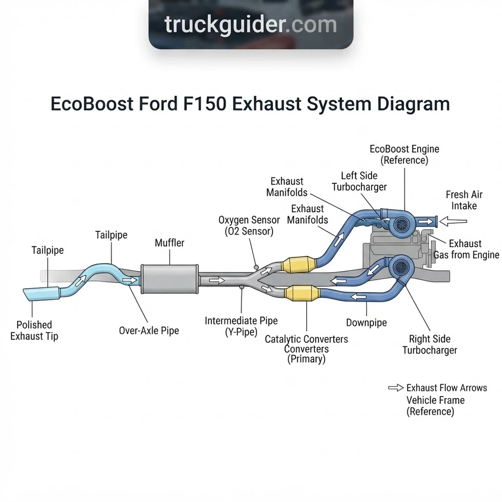
Ford F-150 EcoBoost Exhaust System Diagram and Component Layout
Recommended Best Deal Products


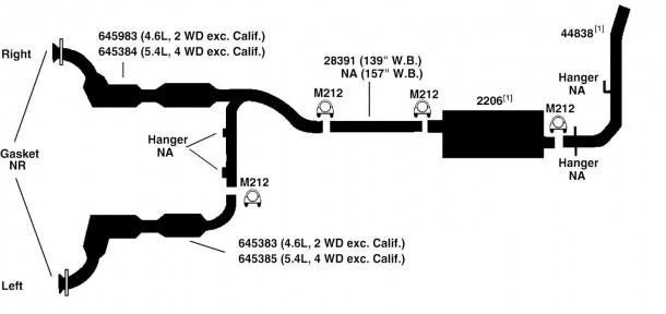
The structural layout of the EcoBoost exhaust platform deviates significantly from traditional naturally aspirated truck architectures. Instead of conventional exhaust manifolds feeding an equalized collector, the EcoBoost system originates at twin engine-mounted turbochargers. Bank 1 (passenger side, cylinders 1-3) and Bank 2 (driver side, cylinders 4-6) feed separate close-coupled downpipes before converging downstream of the transmission crossmember. OEM engineering focuses on preserving gas velocity directly out of the turbine discharge to minimize turbo lag while rapidly elevating catalytic core temperatures during cold-start cycles.
The downpipes incorporate dual dual-substrate catalytic converters matched to high-precision sensor ports. Upstream oxygen sensing is performed via five-wire wideband air-fuel ratio sensors (UEGO) positioned mere inches downstream of the turbine wheel outlet to provide millisecond-grade closed-loop fuel trim adjustments. Downstream sensors utilize four-wire heated planar switching sensors (HEGO) situated past the secondary catalyst washcoat to verify catalytic reduction efficiency. To preserve structural integrity against powertrain pitch and roll under high torque output, Ford integrates double-braided 304 stainless steel flexible couplers into the lower collector assembly.
| Component | OEM / Engineering Role | Material & Construction Spec | Service & Tightening Spec |
|---|---|---|---|
| Twin Turbocharger Downpipes | Connects turbine housings to the mid-exhaust tract; directs expanding exhaust gas away from wastegate ports. | 2.5-inch OD, 409 stainless steel tubing, mandrel-bent; integral heat shielding. | Turbo flange nuts (M10 x 1.25): 40 Nm (30 lb-ft); replace prevailing torque lock nuts upon removal. |
| Catalytic Converters | Dual-stage oxidation/reduction catalyst; oxidizes CO and HC, reduces NOx via precious metal washcoats. | High-flow ceramic monolith cores (400 cpsi factory); dual canning structure with internal ceramic matting. | Maximum permissible pre-cat backpressure: 1.5 psi (10.3 kPa) at 2,500 RPM under loaded cruise. |
| Upstream Wideband O2 (UEGO) | Monitors exact equivalence ratio (lambda) for individual bank stoichiometric fuel regulation. | 5-wire planar sensing element with internal heating circuit (12V PWM controlled). | Thread torque: 47 Nm (35 lb-ft); treat threads exclusively with nickel-based anti-seize. |
| Downstream O2 Sensor (HEGO) | Catalyst efficiency monitoring for OBD-II diagnostics (P0420/P0430 routine). | 4-wire zirconia switching sensor; cycles between 0.1V (lean) and 0.9V (rich). | Thread torque: 47 Nm (35 lb-ft); check sensor harness clearance to driveline (minimum 50mm). |
| Y-Pipe Collector / Merge Section | Converges Bank 1 and Bank 2 downpipe tracts into a single 3.0-inch intermediate exhaust stream. | Dual 2.5-inch inlet into single 3.0-inch outlet; hydroformed collector with internal gas divider. | Flange bolts to intermediate pipe: 48 Nm (35 lb-ft); spherical ball-and-socket seal design. |
| Flexible Coupler (Flex Pipe) | Isolates engine torque reaction and driveline vibration from the rigid chassis exhaust mounts. | Dual-wall corrugated stainless bellows with external 304 wire braid reinforcement. | Visual inspection for collapsed interior liner or ruptured outer braiding; no allowable gas leakage. |
| Resonator Assembly | Eliminates mid-frequency cabin drone (120–180 Hz) generated by the twin V6 exhaust pulses. | Straight-through perforated core wrapped in basalt continuous filament sound absorption packing. | Band clamp torque: 55 Nm (41 lb-ft); ensure minimum 25mm clearance to transmission crossmember. |
| Muffler & Tailpipe Assembly | Broadband decibel attenuation and final exhaust gas routing beyond the rear passenger tire. | Multi-chambered internal baffle design with drainage weep holes; 3.0-inch mandrel-bent tailpipe. | Hanger isolator bracket bolts: 30 Nm (22 lb-ft); ensure EPDM rubber isolators are fully engaged. |
When servicing the factory downpipe assembly, always disconnect the negative 12V battery terminal prior to handling sensor harnesses. The PCM performs periodic key-off heater circuit resistance calibrations; sudden circuit disruption can set persistent P0030/P0050 heater performance codes stored in non-volatile KAM (Keep Alive Memory).
How to Trace an EcoBoost Ford F150 Exhaust Diagram Step by Step

Following the signal path and thermodynamic flow through an ecoboost ford f150 exhaust system diagram requires understanding both physical gas routing and electrical data interaction. Diagnostic tracing must proceed systematically from the combustion chamber exit to the atmospheric termination point.
- Turbine Housing Discharge and Internal Wastegate Bypass: Exhaust gas exits the engine cylinder heads and directly drives the turbine wheels of the Garrett or BorgWarner turbochargers. The factory exhaust diagram illustrates a divided discharge: gas either spins the turbine wheel to generate boost or bypasses it via the internal wastegate valve under the command of the electronic wastegate actuator. Both gas streams unite inside the turbine housing snout, creating high-turbulence, high-heat discharge directly upstream of the downpipe connection.
- Bank-Specific Downpipe and Upstream Wideband Analysis: Entering the 2.5-inch downpipes, the exhaust immediately encounters the factory wideband UEGO sensors. At this junction on the schematic, verify that sensor wiring harness routing maintains proper clearance from the turbocharger heat shields. The gas stream passes the primary catalyst brick, where high temperatures (typically 650°C to 850°C under load) incinerate unburned hydrocarbons and carbon monoxide.
- Post-Catalyst Diagnostic Evaluation: After clearing the primary and secondary catalytic reduction bricks, the cleaned exhaust flows across the downstream HEGO sensors. On the electrical layout, these sensors return a steady 0.6V to 0.8V signal to the PCM under normal closed-loop conditions. A voltage signal mimicking the upstream sensor indicates compromised catalytic washcoat performance, precipitating OBD-II fault alerts.
- Collector Merge and Kinetic Scavenging: The Bank 1 and Bank 2 pipes route downward toward the transmission bellhousing, meeting at the Y-pipe collector. The schematic designates a merge angle engineered to balance opposing cylinder bank backpressure waves. At this junction, the dual 2.5-inch lines terminate into a single 3.0-inch intermediate tract, transitioning through an integrated flexible bellows that absorbs engine movement under heavy torque loads without binding the downstream chassis hangers.
- Intermediate Extension, Resonator Expansion, and Tailpipe Egress: The unified 3.0-inch flow passes through a straight-through resonator designed to dampen cabin-intrusive frequencies. Gas then flows through an intermediate extension pipe—configured to the vehicle’s specific wheelbase—before entering the large-case OEM transverse or longitudinal muffler. Within the muffler, internal louvered tubes reduce broad-spectrum sound energy before the exhaust exits through the mandrel-bent over-axle tailpipe assembly, terminating behind the right rear wheel well.
EcoBoost Exhaust Blueprint Variations: 2.7L vs 3.5L and Wheelbase Layouts
Recommended Best Deal Products


The F-150 platform utilizes distinct engine families and multiple chassis lengths, each dictating substantial changes to the exhaust blueprint. When replacing or modifying exhaust components, technicians must identify whether the vehicle utilizes the first- or second-generation Ford 3.5L EcoBoost V6 or the compacted-graphite iron (CGI) architecture of the Ford 2.7L Nano EcoBoost V6.
The primary engineering divergence resides at the cylinder head interface. The 2.7L Nano EcoBoost incorporates water-cooled exhaust manifolds cast directly into the cylinder heads. Consequently, the turbochargers bolt directly to the cylinder head assembly via a 3-bolt turbine pattern, and the downpipes utilize specific proprietary flanges. In contrast, the 3.5L EcoBoost relies on individual cast iron exhaust manifolds secured to the cylinder heads with studs; these feed separate turbos mounted lower and farther outward on the engine block. Furthermore, downpipe orientation, sensor bung placement angles, and intermediate pipe lengths vary based on cab and bed dimensions.
| Engine & Wheelbase Configuration | Manifold & Flange Blueprint | Downpipe & Y-Pipe Configuration | Intermediate Pipe Service Length |
|---|---|---|---|
| 2.7L Nano V6 (141.1″ WB / Reg Cab 8′ Bed) | Integrated head manifold; 3-bolt turbine discharge flange with embossed stainless crush ring. | Narrow-track downpipes; specific catalytic converter heat shield mounting tabs. | 39.5 inches (1,003 mm); requires wheelbase adapter extension sleeve. |
| 2.7L Nano V6 (145.0″ WB / SuperCrew 5.5′ Bed) | Integrated head manifold; 3-bolt turbine discharge flange. | Direct-fit downpipes converging at transmission crossmember flange. | 43.4 inches (1,102 mm); standard factory production intermediate pipe length. |
| 3.5L EcoBoost V6 (145.0″ WB / SuperCab 6.5′ Bed) | External cast manifold; 2-bolt downpipe turbine outlet with flare-and-cone mechanical seal. | Wide-stance downpipes; larger internal catalyst volume (high-load thermal package). | 43.4 inches (1,102 mm); direct flange-to-resonator mounting. |
| 3.5L EcoBoost V6 (156.8″ WB / SuperCrew 6.5′ Bed) | External cast manifold; dual-plane downpipe attachment studs (M10 x 1.25). | Heavy-duty 3.0-inch Y-collector with integrated transmission crossmember hanger. | 55.2 inches (1,402 mm); extended intermediate segment with secondary center hanger. |
| 3.5L EcoBoost V6 (163.7″ WB / SuperCab 8.0′ Bed) | External cast manifold; standard 3.5L twin-turbo configuration. | Heavy-duty 3.0-inch Y-collector assembly matching high-capacity cooling packages. | 62.1 inches (1,577 mm); modular intermediate pipe using dual-clamp sleeve unions. |
Factory Ford exhaust slip-fit connections require an overlap of precisely 2.0 inches (50.8 mm) prior to torquing OEM Torca-style band clamps. Under-inserting the intermediate pipe compromises joint rigidity, shifting the exhaust hanger load distribution and causing premature stress-cracking at the flex bellows.
Troubleshooting EcoBoost Exhaust Leaks, Vibrations, and Fault Codes
Diagnosing an EcoBoost exhaust tract requires isolating hardware failures from sensor degradation. Due to the high cyclic heat loading generated by forced induction, standard maintenance routines must include visual, acoustic, and digital diagnostic evaluations.
The most widespread mechanical failure on first- and second-generation 3.5L EcoBoost engines involves exhaust manifold warpage. The rear mounting studs (specifically cylinder 3 on Bank 1 and cylinder 6 on Bank 2) experience extreme shear stress due to thermal expansion differentials between the cast iron manifold and the aluminum cylinder head. A warped manifold allows high-pressure exhaust gasses to bypass the turbine wheel during spool-up, producing a distinct high-frequency chirp or squeal under boost conditions. This leak introduces unmetered oxygen upstream of the UEGO sensor, corrupting fuel trims and triggering false lean diagnostic trouble codes (DTCs).
Downstream within the physical exhaust system layout, the double-braided flexible coupler in the Y-pipe collector is subject to rotational stress and fatigue failure. Tearing of the internal corrugated bellows creates an audible ticking leak under acceleration and allows oxygen intrusion during closed-throttle deceleration. This condition frequently sets false catalyst efficiency codes:
- P0420 / P0430 (Catalyst System Efficiency Below Threshold – Bank 1 / Bank 2): When downstream HEGO sensors detect switching activity exceeding 0.2 cycles per second (mirroring the upstream wideband sensor), the PCM flags catalyst degradation. Before condemning expensive catalytic converters, verify flex pipe integrity, test the intermediate joint for black carbon trails, and verify downstream sensor heater circuits.
- P0131 / P0151 (O2 Sensor Circuit Low Voltage – Bank 1, Sensor 1 / Bank 2, Sensor 1): Typically triggered by physical harness abrasion against the transmission case, oil contamination from leaking valve covers, or an open circuit in the sensor’s internal reference cell.
- P0030 / P0050 (HO2S Heater Control Circuit – Bank 1, Sensor 1 / Bank 2, Sensor 1): Confirms an open or high-resistance fault in the 12V pulse-width modulated heater line. The upstream UEGO internal resistance must register between 2.1 and 3.5 ohms at 20°C (68°F); readings outside this range confirm an internal element failure requiring sensor replacement.
Do not use silicone-based sealants or RTV anywhere upstream of the catalytic converters or in proximity to O2 sensor threads. Outgassing of silicates instantly glazes the platinum-rhodium substrate of the wideband O2 sensors, rendering them completely chemically inactive and permanently corrupting the PCM’s closed-loop air-fuel calculations.
Internal structural failures also occur within the resonator and muffler. Moisture accumulation due to repeated short trip cycles can rot the internal baffle welds of the factory straight-through resonator. This creates an erratic metallic buzzing or rattling noise at 1,600–2,100 RPM under partial engine load, often misdiagnosed as transmission crossmember or turbocharger wastegate rattle.
Analyzing the EcoBoost Ford F150 Exhaust System Diagram vs 5.0L V8
Recommended Best Deal Products


Contrasting the twin-turbocharged EcoBoost platform schematic against naturally aspirated V8 and hybrid powertrains reveals fundamental mechanical divergences:
- Exhaust Manifold and Scavenging Dynamics: The naturally aspirated Ford F-150 5.0L Coyote V8 exhaust uses long-runner tubular factory headers that rely on kinetic pulse scavenging to assist in cylinder evacuation. The 3.5L and 2.7L EcoBoost systems prioritize minimal runner volume to maximize the enthalpy delivered to the turbine impellers, accepting high localized manifold pressure in exchange for near-instantaneous boost generation.
- Acoustic and Backpressure Requirements: Turbochargers chop the primary sound waves of the EcoBoost exhaust, functioning as primary sound attenuators. Because the turbochargers consume substantial pulse energy, the downstream system can utilize straight-through resonators without excessive cabin intrusion. Conversely, the 5.0L Coyote requires larger expansion chambers and multi-baffle mufflers to control drone across broad RPM bands.
- Hybrid System Architectures: The Ford F-150 PowerBoost Hybrid exhaust schematic integrates an engine coolant heat recovery system directly downstream of the Y-pipe collector. This routing cycles exhaust heat through a dedicated liquid-to-gas heat exchanger to accelerate engine and transmission warm-up cycles, a component absent from standard EcoBoost and Coyote layouts.
- Aftermarket Cat-Back System Compatibility: Installing an aftermarket cat-back exhaust kit downstream of the factory Y-pipe provides lower acoustic backpressure gains on an EcoBoost than on a naturally aspirated engine. While a 5.0L benefits from tuned pipe lengths to match atmospheric scavenging, an EcoBoost system achieves maximum performance when post-turbo backpressure is minimized entirely. The primary power limitation on the EcoBoost resides within the downpipes and catalytic core density rather than the rear exhaust tract.
Frequently Asked Questions About EcoBoost F150 Exhaust Schematics
What size is the factory exhaust tubing on an F-150 EcoBoost?
The OEM exhaust system layout utilizes dual 2.5-inch outer diameter (OD) 409 stainless steel downpipes from the turbocharger turbine housings down to the merge collector. From the Y-pipe junction downstream through the resonator, intermediate pipe, and main muffler, the system transitions into a single 3.0-inch OD pipe. The final tailpipe section over the rear axle retains the 3.0-inch OD specification out to the exit tip.
Why do 3.5L EcoBoost exhaust manifolds warp and snap rear mounting studs?
The factory cast iron exhaust manifold on first- and second-generation 3.5L EcoBoost engines has fewer mounting studs on the perimeter runners than ideal for high-thermal-load towing. Under prolonged boost conditions, exhaust gas temperatures can exceed 900°C (1,650°F), inducing severe thermal expansion. Because the aluminum cylinder head expands at a different rate than the cast iron manifold, the rear studs—typically cylinder 3 and cylinder 6—experience excessive shear forces, leading to structural fatigue, stud failure, and loud exhaust leaks at the cylinder head face.
Can I run an aftermarket 3.5L downpipe on a 2.7L EcoBoost?
No. The 2.7L Nano EcoBoost and the 3.5L EcoBoost have completely incompatible downpipe mounting configurations. The 2.7L features integrated water-cooled exhaust manifolds cast inside the cylinder head, positioning the turbochargers with a distinct 3-bolt triangular discharge flange. The 3.5L features external exhaust manifolds with lower, outward-mounted turbochargers utilizing a 2-bolt downpipe connection. The two designs cannot be interchanged without custom fabrication.
How does the downstream O2 sensor differ from the upstream sensor on the EcoBoost schematic?
The upstream sensor is a five-wire wideband Universal Exhaust Gas Oxygen (UEGO) sensor that continuously measures the precise air-fuel ratio (equivalence ratio / lambda) across rich, stoichiometric, and lean ranges to dictate real-time fuel injector pulse widths. The downstream sensor is a standard four-wire Heated Exhaust Gas Oxygen (HEGO) switching sensor that operates narrowly around 0.45V, serving primarily to verify that the catalytic converters are successfully storing oxygen and neutralizing harmful emissions.
Does deleting the factory resonator cause cabin drone under towing loads?
Yes. The EcoBoost V6 generates severe mid-frequency exhaust pulses between 120 Hz and 180 Hz when operating under load between 1,800 and 2,400 RPM. The factory straight-through resonator is engineered specifically to eliminate these acoustic wavelengths. Deleting the resonator or replacing it with a non-baffled straight pipe introduces significant low-frequency cabin resonance (drone), which becomes particularly fatiguing during sustained highway cruising and heavy trailer towing.
Step-by-Step Guide to Understanding the Ecoboost Ford F150 Exhaust System Diagram
Identify – Consult the diagram to verify your EcoBoost engine displacement (2.7L vs. 3.5L) and cab-bed wheelbase configuration.
Locate – Locate the twin downpipe flanges beneath the turbos, tracing past the crossmember to find all rubber isolator hangers.
Reference – Reference the diagram’s component layout to inspect O2 sensor bungs, catalytic converter shells, and slip-fit band clamp orientations.
Connect/Route – Route replacement piping over the rear axle assembly, aligning hanger prongs with factory chassis isolators before tightening clamps.
Verify – Verify pipe-to-chassis clearances, check heat shield spacing, and torque all spherical band clamps to 35–40 lb-ft.
Troubleshoot – Start the engine to detect hiss or ticking noises along flange joints, retorquing fasteners if joint leaks are present.