7-Way Toyota Tacoma Trailer Wiring Harness Diagram: Pinout & Wiring 2026

The Toyota Tacoma 7-way harness features a standard RV blade configuration. Pin 1 is Ground (White), Pin 2 is Electric Brakes (Blue), Pin 3 is Tail/Running Lights (Green), Pin 4 is 12V Auxiliary Power (Black), Pin 5 is Right Turn/Stop (Brown), Pin 6 is Left Turn/Stop (Yellow), and Pin 7 is Reverse Lights (Purple).
📌 Key Takeaways
- Standard RV blade 7-way connectors utilize a 12V auxiliary power circuit (Pin 4) protected by a 30A fuse in the engine bay.
- The Blue wire (Pin 2) must originate from the brake controller unit under the dashboard to actuate trailer brakes.
- Always verify continuity using a digital multimeter set to DC voltage before finalizing any splice or terminal crimp.
- Corrosion at the rear bumper junction box is the most common failure point for intermittent running lights and turn signals.
- If you encounter complex electrical shorts within the integrated Tacoma harness, consult an ASE-certified technician to avoid damaging the truck’s ECU.
Whether you are preparing a Toyota Tacoma for heavy-duty towing or troubleshooting a lighting failure on a utility trailer, understanding the electrical architecture is paramount. The Toyota Tacoma trailer wiring harness diagram serves as the master blueprint for integrating your vehicle’s lighting and braking systems with your towed equipment. Properly mapping the RV blade connector and auxiliary power circuits ensures that your turn signals, running lights, and electric brakes function reliably under diverse load conditions. This guide examines the factory-integrated towing package, aftermarket integration points, and the precise terminal definitions required to maintain OEM standards for long-term electrical integrity.

Prime for Young Adults — 6 Months Free
Students and 18–24s get six months of Prime free, then half price.
Start 6 Months Free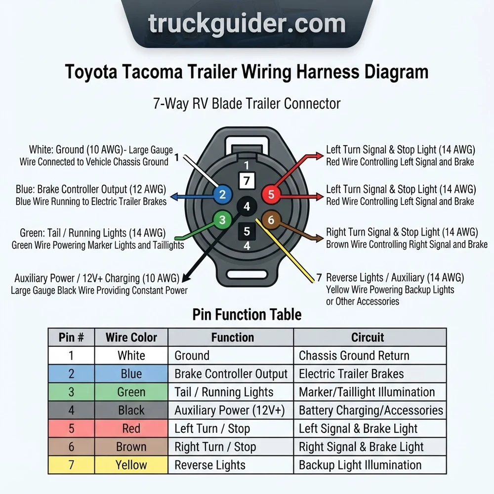
Toyota Tacoma Trailer Wiring Harness Diagram: Component Breakdown
Recommended Best Deal Products


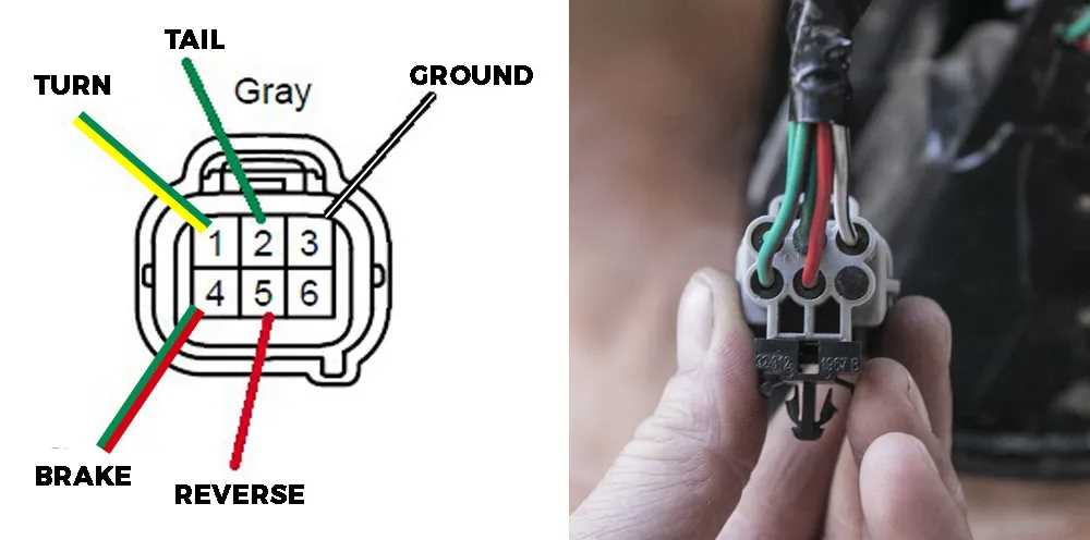
The factory Tacoma towing package utilizes a sophisticated electrical distribution system designed to isolate the vehicle’s ECU from the high-current demands of trailer lighting and electric brake systems. At the core of this system is the tow converter module, which acts as an intermediary, receiving low-amperage signals from the vehicle’s lighting circuits and switching higher-amperage power directly from the battery or high-current fuse block.
The primary connection point is typically a 7-Way RV blade connector. Unlike a simple flat connector, the 7-way system provides specialized pins for auxiliary power and electric brake controller integration. This configuration allows for the operation of heavy-duty trailers equipped with battery banks or interior lighting. The integration is usually achieved through a T-One connector harness that plugs directly into the vehicle’s tail light assemblies, intercepting the signal before it reaches the bulbs.
Within the wiring harness architecture, you will identify three distinct sub-systems. First is the signal lighting system, which processes the left turn signal, right turn signal, and running lights. Second is the braking and power system, which includes the brake controller lead—an essential component for controlling the electric brake magnets on a trailer. Finally, the grounding system is critical; it utilizes a dedicated heavy-gauge ground pin to prevent voltage drop and ground-loop feedback, which are common culprits behind flickering LEDs or intermittent signal malfunctions.
When inspecting your system, pay close attention to the tow converter box. This module is prone to moisture intrusion if mounted improperly near the rear bumper. Ensure the module is secured in a location shielded from road debris and water spray. If your Tacoma was not equipped with the factory tow package, you may be relying on a third-party harness; these units often require a dedicated 12-volt power lead run directly from the battery to a converter mounted near the hitch. Proper routing of this power lead, secured with split-loom tubing and frame-mounted clips, is essential to prevent chafing against the chassis.
Most Tacoma models from 2016-2023 utilize a standard 7-way vehicle side socket. If you are retrofitting a 4-way flat connector, ensure you are using a powered converter rather than a direct-splice method to avoid triggering the vehicle’s current-sensing protection.
Toyota Tacoma Trailer Wiring Harness Diagram: Pin Assignment Table

Correct pin identification is vital for avoiding short circuits or system failures. The table below outlines the standard configuration for the 7-way RV blade connector and the standard 4-way flat connector integration often found on Tacomas.
| Pin Position | Function | Description |
|---|---|---|
| 1 | Ground | Common Ground Pin (White) |
| 2 | Electric Brake | Signal from Brake Controller (Blue) |
| 3 | Tail/Running | Running Lights/Clearance (Brown) |
| 4 | Auxiliary Power | 12V+ Battery Feed (Black) |
| 5 | Left Turn/Brake | Combined Signal (Yellow) |
| 6 | Right Turn/Brake | Combined Signal (Green) |
| 7 | Reverse Light | Auxiliary Reverse Signal (Purple) |
When referencing the 4-way flat connector, the sequence remains standard across the industry: Ground (White), Running Lights (Brown), Left Turn/Brake (Yellow), and Right Turn/Brake (Green). Always verify your trailer plug matches the truck socket orientation before connecting, as incorrect alignment can lead to fuse failure in the Tacoma’s towing distribution block. If you are troubleshooting a brake controller, ensure the Blue wire (Pin 2) registers a variable voltage increase when the manual override lever is engaged.
Standard Wire Color Reference for Tacoma Trailer Systems
Recommended Best Deal Products


While Toyota’s internal harness colors may vary by production plant and model year, the aftermarket standard for T-One connectors and trailer adapters is consistent. Utilizing these colors during installation allows for rapid diagnostic testing with a multimeter or circuit tester.
| Wire Color | Application | Notes |
|---|---|---|
| White | Ground | Ensure chassis-to-frame metal-to-metal contact. |
| Brown | Running Lights | Active when headlight switch is engaged. |
| Yellow | Left Turn/Brake | Combined signal circuit. |
| Green | Right Turn/Brake | Combined signal circuit. |
| Blue | Electric Brake | Output from cab-mounted controller. |
| Black | 12V Aux Power | Requires in-line fuse near battery. |
If you are performing a repair on an older vehicle, color-coding may have faded due to UV exposure or road salt contamination. In such cases, identify the pin function by location on the connector face rather than wire color. Always use high-quality heat-shrink butt connectors; never use electrical tape for connections exposed to the exterior environment, as the vibration and thermal cycling common in Tacoma usage will cause the adhesive to fail, leading to short circuits.

Audible — Listen Free for 30 Days
One free credit a month and thousands of titles included.
Listen Free for 30 DaysHow to Install a Toyota Tacoma Trailer Wiring Harness
Installing a wiring harness on a Tacoma requires attention to detail regarding chassis grounding and module placement. Before beginning, ensure the vehicle ignition is OFF to prevent accidental shorts.
1. Access the Taillights: Remove the rear tail light assemblies to gain access to the factory harness connectors. Use a plastic trim panel tool to avoid marring the paint or damaging the clips.
2. Install the T-One Connector: Plug the T-connector harness between the vehicle’s factory wiring and the tail light housing. Listen for the audible click of the locking tabs.
3. Secure the Converter Module: Using the provided adhesive strips or nylon zip-ties, mount the tow converter in a high, dry location behind the tail light cavity or near the frame rail. Ensure the module is not resting against hot exhaust components.
4. Route the 12V Power Lead: Run the bundled black power wire from the converter module along the vehicle’s frame, following existing factory wiring paths. Secure the wire using cable ties at 12-inch intervals. Use a protective split-loom sleeve to prevent abrasion.
5. Make the Battery Connection: Connect the 12V lead to the positive battery terminal via an in-line fuse holder. Install a 15-20 amp fuse (depending on your specific converter specs) and test the power at the trailer connector with a multimeter.
6. Verify Grounding: Attach the white ground wire directly to the chassis using a ring terminal and a self-tapping screw. Ensure the contact area is sanded to bare metal to ensure low resistance.
Always ensure a chassis ground point is free of rust or undercoating. A resistance reading of more than 0.5 ohms between the ground pin and the truck frame indicates a compromised ground path.
Avoiding Common Toyota Tacoma Trailer Wiring Harness Pitfalls
Recommended Best Deal Products


Many electrical issues originate from incorrect installation techniques or environmental factors that degrade the harness over time. By adhering to the following best practices, you can prevent common failures.
Avoid Direct Splices: Do not splice directly into the Tacoma’s wiring. Modern Toyota electrical systems use pulse-width modulation (PWM) or current-sensing protocols that will interpret a direct-splice trailer load as a short circuit, resulting in a blown fuse or a disabled lighting circuit.
Protect the Converter Box: Never mount the converter module in the open where it can be sprayed by tire-thrown water. Excessive moisture will corrode internal circuit board traces.
Secure All Wires: Vibration is the primary cause of harness failure. Use UV-rated cable ties every 8-12 inches to prevent wire slack from rubbing against the suspension or exhaust.
Check the Ground Pin: If your running lights operate but the turn signals fail, the ground pin is likely loose or oxidized. A bad ground often causes “feedback,” where lights dim or flash unintentionally because the current is searching for a path of least resistance.
* In-line Fuse Integrity: Always install the required fuse as close to the vehicle battery as possible. If the power wire shorts to the frame between the battery and the converter, an improperly placed fuse will not prevent a fire.
Using a test light instead of a digital multimeter can draw too much current for sensitive ECU-controlled systems in later model Tacomas. Always use a high-impedance digital multimeter for diagnostic work.
Toyota Tacoma Trailer Wiring Harness Diagram Questions Answered
Can I convert my 4-way flat connector to a 7-way RV blade?
Yes, however, you will need to install a 7-way adapter kit that includes a dedicated 12V battery feed and a brake controller lead. Since the 4-way flat connector only provides signal and ground, you cannot power electric brakes or auxiliary trailer interior lights without running the additional wires required for the 7-way configuration.
Why do my trailer lights flicker when the truck turn signals are on?
This is typically caused by a poor ground pin connection. When the turn signal load is added to the system, the high resistance at the ground connection point causes voltage to sag, resulting in the other lights dimming or flickering. Clean your chassis ground point to bare metal and verify the wire crimp is secure.
Audible Premium Plus — Annual Membership
12 audiobook credits up front, plus the full Audible catalogue.
See Annual PlansDo I need a separate brake controller if my trailer has electric brakes?
Yes, a brake controller is required to modulate the current sent to the trailer’s electric brakes. The Toyota Tacoma wiring harness provides the necessary “Blue” signal wire lead, but the controller itself must be installed in the cab and spliced into the brake switch and the designated brake lead.
What fuse size should I use for the auxiliary power wire?
The fuse size is determined by the manufacturer of your trailer wiring harness. Most converters require a 15-amp to 20-amp fuse. Check the instructions provided with your T-connector harness; exceeding the manufacturer’s recommended fuse amperage can lead to melted wires and harness failure during a short circuit event.
How do I test the tow converter box for failure?
Using a multimeter, verify that you have 12V power input at the converter’s battery lead. Then, verify that you have signal voltage input from the vehicle’s tail light harness wires. If you have input power and signal, but no output on the trailer-side wires, the converter box has likely failed and requires replacement.
Step-by-Step Guide to Understanding the Toyota Tacoma Trailer Wiring Harness Diagram
Identify – Locate the 7-way factory connector mounted near the Tacoma receiver hitch.
Locate – Access the engine bay fuse box to ensure the towing package fuses are seated correctly.
Reference – Use the pinout diagram to match wire colors to the specific trailer functions.
Connect/Route – Secure the harness wiring away from heat sources and sharp metal edges using high-temp zip ties.
Verify – Connect a tester to the outlet and cycle all turn signal, brake, and light inputs to confirm signal integrity.
Troubleshoot – Inspect terminal pins for corrosion and apply dielectric grease if connections are inconsistent.