Vacuum 5.9 Magnum Engine Diagram: Diagnosis & Fix Guide
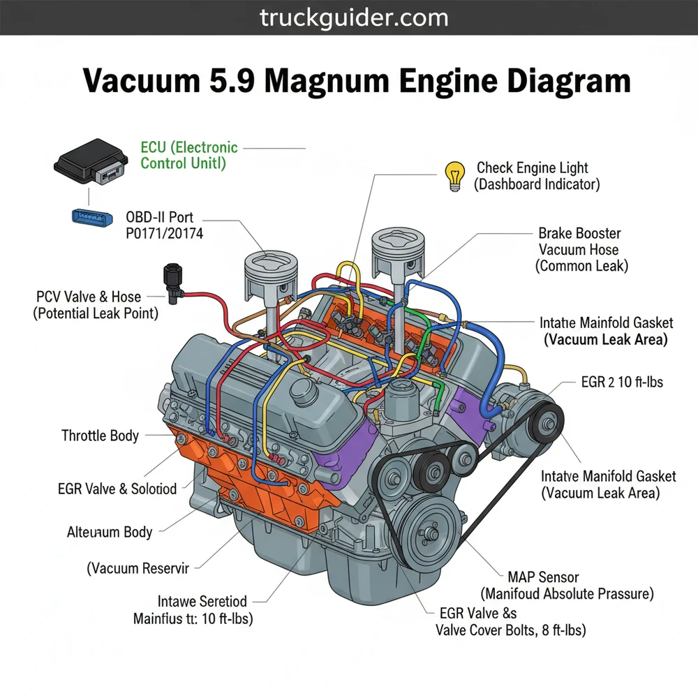
A vacuum 5.9 magnum engine diagram illustrates the network of hoses connecting the intake manifold to components like the brake booster, PCV valve, and cruise control servo. This map is essential for tracing leaks that cause lean conditions, ensuring all ports are sealed to maintain proper idle quality and engine performance.
📌 Key Takeaways
- Identifies the complex routing of vacuum lines for the 5.9L Dodge/Jeep engine.
- Helps pinpoint the source of intake leaks causing erratic engine behavior.
- Ensuring secure connections prevents lean codes and poor fuel economy.
- Always check the plenum gasket as a primary failure point in these engines.
- Essential for visual confirmation after performing intake manifold repairs.
Navigating the complexities of a 5.9L Magnum V8 engine requires more than just mechanical intuition; it demands a precise understanding of how the engine breathes and regulates itself. Whether you are restoring a classic Ram truck, a Jeep Grand Cherokee ZJ, or a Dodge Durango, having a clear vacuum 5.9 magnum engine diagram is the cornerstone of any successful repair or maintenance project. Vacuum leaks are notorious for causing erratic behavior, from surging idles to “wild vents” where your AC only blows through the defroster. This guide is designed to provide you with a comprehensive visual and technical breakdown of the vacuum system, ensuring you can identify every hose, port, and sensor. By the end of this article, you will understand how the vacuum system interacts with the ECU, how to troubleshoot common diagnostic codes, and the best practices for maintaining the long-term health of your Magnum engine.
The 5.9 Magnum engine relies on a “Speed Density” system. This means the ECU uses the Manifold Absolute Pressure (MAP) sensor to calculate air mass rather than a Mass Air Flow (MAF) sensor. Consequently, even a pinhole vacuum leak can significantly disrupt the air-fuel ratio, leading to poor performance and fuel economy.
The 5.9 Magnum vacuum system is a network of rubber and hard plastic lines that distribute negative pressure from the intake manifold to various critical components. At the heart of this system is the throttle body and the upper intake plenum. Unlike modern engines that use electronic actuators for almost everything, the Magnum V8 utilizes vacuum for the Positive Crankcase Ventilation (PCV) system, the Brake Booster, the Cruise Control servo, and the Evaporative Emission (EVAP) system.
The diagram for this engine typically highlights three primary regions of vacuum draw. First is the front of the throttle body, which usually houses the large port for the PCV valve and a smaller port for the EVAP canister purge solenoid. Second is the rear of the intake manifold, where you will find the MAP sensor mounted directly to the manifold or connected via a very short, specific vacuum elbow. Third is the massive port located on the driver-side rear of the manifold, which supplies the power brake booster. There is also a vacuum reservoir, often shaped like a “football” or integrated into the cowl, which stores vacuum to ensure the HVAC doors and cruise control function even under high-load, low-vacuum conditions (like climbing a steep hill).
Variations in the diagram frequently occur depending on the vehicle’s drive configuration. For instance, four-wheel-drive models equipped with a vacuum-actuated Central Axle Disconnect (CAD) will feature an additional set of lines running from the transfer case up to the engine bay. These lines are a frequent source of failure, often resulting in the 4WD failing to engage while simultaneously causing a vacuum leak that affects engine idling. Identifying these differences is crucial when looking at a generic vacuum 5.9 magnum engine diagram, as the core engine ports remain the same, but the distribution “tees” will vary.
Never attempt to diagnose vacuum leaks with a running engine in a closed garage. Additionally, be extremely cautious when using flammable “starter fluid” to find leaks around the hot exhaust manifolds of the 5.9 Magnum, as this poses a significant fire risk.
Reading and interpreting the vacuum 5.9 magnum engine diagram is the first step toward a functional repair. Follow these steps to ensure you are routing and testing your system correctly:
- ✓ 1. Identify the Source: Locate the main vacuum ports on the throttle body and the intake manifold plenum. The manifold is the “source” of the vacuum, while components like the cruise control are the “consumers.”
- ✓ 2. Map the Main Lines: Trace the largest line from the rear driver-side of the intake manifold to the brake booster. Ensure the check valve on the booster is functional and the grommet is not dry-rotted.
- ✓ 3. The PCV Path: Trace the hose from the passenger-side valve cover (the PCV valve) to the front or side port of the throttle body. Ensure the hose is oil-resistant, as standard rubber will swell and collapse.
- ✓ 4. EVAP Routing: Locate the EVAP purge solenoid, usually mounted on the inner fender or near the radiator shroud. Route the line from the solenoid back to the designated port on the throttle body.
- ✓ 5. HVAC and Cruise Control: Follow the small plastic “hard lines” that typically run along the firewall. These supply vacuum to the interior dash vents and the cruise control servo located under the battery tray.
- ✓ 6. The MAP Sensor Check: Ensure the MAP sensor is seated tightly. On many 5.9 Magnums, this sensor is held by two screws on the back of the throttle body/manifold interface. A leaking O-ring here is a common but overlooked issue.
- ✓ 7. Leak Testing: Use a handheld vacuum pump to test individual components like the cruise control servo or the HVAC actuators to see if they hold pressure.
To perform these tasks, you will need a basic set of tools including a vacuum gauge, a handheld vacuum pump (like a Mityvac), various sizes of vacuum hose (3/32″, 5/32″, and 7/32″ are common), and a pair of long-reach needle-nose pliers for those hard-to-reach ports behind the manifold.
If you are replacing the factory hard plastic lines, consider upgrading to silicone vacuum tubing. Silicone is much more resistant to the high under-hood heat generated by the 5.9 Magnum and won’t become brittle and crack like the OEM plastic lines.
The 5.9 Magnum engine is famous for one particular failure that mimics an external vacuum leak: the “Belly Pan” or intake plenum gasket failure. The intake manifold is a two-piece design with a steel plate bolted to the bottom of the aluminum manifold. Over time, the gasket between these two parts fails. Because the area inside the plenum is under vacuum, it begins to suck oil and air from the lifter valley into the combustion chamber. This creates a massive internal vacuum leak. Common symptoms include a persistent “check engine light,” high oil consumption, and spark knock (detonation) under load.
When troubleshooting, look for diagnostic codes via the OBD-II port. A P0171 (Lean Bank 1) or P0174 (Lean Bank 2) often indicates the ECU is trying to compensate for extra air entering the system through a vacuum leak. If your idle is high or fluctuating, the MAP sensor may be sending incorrect data to the ECU due to a cracked vacuum elbow. Another frequent issue is the “Wild Vent” syndrome mentioned earlier. If your air conditioning switches from the vents to the defroster whenever you accelerate, you have a leak in the vacuum line or the check valve leading to the vacuum reservoir.
If you have replaced all external lines and still have a rough idle or lean codes, it is time to perform a “smoke test.” By injecting smoke into the vacuum system, you can visually identify where the smoke escapes. If smoke pours out from under the intake manifold, your plenum gasket is blown. At this point, it is recommended to seek professional help or prepare for a significant DIY project involving the removal of the intake manifold, accessory belt, and alternator to access the plenum.
When servicing the intake manifold to fix vacuum leaks, always adhere to the specific torque spec for the manifold bolts. The sequence usually starts from the center and works outward to 12 ft-lbs, then a final pass at 15 ft-lbs. Over-tightening can crack the aluminum manifold ears.
Maintaining the vacuum system is an ongoing process. During your regular oil changes, take a moment to inspect the accessory belt and the coolant flow around the thermostat housing. While these might seem unrelated, a failing water pump or a slipping belt can cause localized overheating that accelerates the degradation of nearby vacuum lines. Furthermore, when the timing chain eventually stretches—a common high-mileage trait of the 360 Magnum—the engine’s timing becomes slightly retarded, which lowers the overall manifold vacuum and can cause sensors to behave erratically.
For those looking to save costs, do not just buy “generic” vacuum line by the foot if the application requires a pre-bent elbow. The 90-degree elbows on the MAP sensor and the PCV system are specifically designed not to collapse under high heat. Using a standard soft rubber hose in these locations will often lead to the hose “sucking shut” as it warms up, creating a blockage that the ECU cannot account for.
When it comes to quality components, always opt for name-brand sensors (like Mopar or NTK) for the MAP and O2 sensors. The 5.9 Magnum ECU is notoriously picky about sensor voltages. An “off-brand” sensor might fit the plug but provide a signal that is just slightly out of range, keeping that frustrating check engine light illuminated even if the vacuum leak itself has been fixed.
In summary, the vacuum 5.9 magnum engine diagram is more than just a map of hoses; it is a guide to the health and efficiency of one of the most reliable V8 engines ever built. By understanding how the manifold vacuum interacts with the ECU, the EVAP system, and the braking system, you can ensure your vehicle remains safe and powerful. Regular inspections, using the correct diagnostic codes for guidance, and choosing high-quality replacement parts will keep your Magnum V8 running smoothly for hundreds of thousands of miles. Whether you are chasing a P0171 code or just tidying up the engine bay, a methodical approach to the vacuum system is always the best path to success.
Step-by-Step Guide to Understanding the Vacuum 5.9 Magnum Engine Diagram: Diagnosis & Fix Guide
Identify the specific vacuum ports on the intake manifold using the vacuum 5.9 magnum engine diagram.
Locate the main lines leading to the brake booster and PCV valve for initial inspection.
Understand how the vacuum flows from the manifold to the EVAP system and HVAC controls.
Connect new hoses or tighten clamps according to the factory layout shown in the diagram.
Verify that the intake manifold bolts meet the correct torque spec to prevent internal vacuum leaks.
Complete the process by using an OBD-II scanner to reset the check engine light if needed.
Frequently Asked Questions
Where is the vacuum 5.9 magnum engine diagram located?
Under the hood of most Dodge or Jeep vehicles, you will find the vacuum 5.9 magnum engine diagram on the VECI (Vehicle Emission Control Information) label. This sticker is typically located on the radiator core support or the underside of the hood for quick reference during repairs.
What does the vacuum 5.9 magnum engine diagram show?
The diagram provides a visual map of the vacuum hoses connecting the intake manifold to accessories like the MAP sensor, EVAP canister, and brake booster. It ensures every vacuum-operated component receives the correct pressure required for the ECU to manage the engine efficiently.
How many vacuum connections does the 5.9 Magnum have?
Most 5.9 Magnum engines feature roughly five to seven primary vacuum ports on the intake manifold. These service the PCV system, brake booster, fuel pressure regulator, and HVAC controls, though exact counts vary depending on the specific vehicle model and emission package.
What are the symptoms of a vacuum leak in a 5.9 Magnum?
Common signs include a rough idle, high RPM at stoplights, and a check engine light for lean codes. If the vacuum lines fail, the ECU cannot manage air-fuel ratios properly, leading to poor acceleration and potential stalling under load or while idling.
Can I replace vacuum lines on a 5.9 Magnum myself?
Yes, replacing cracked or brittle vacuum hoses is a straightforward DIY task. Use the vacuum 5.9 magnum engine diagram to swap lines one by one to avoid confusion, ensuring each new hose is seated firmly on its port to prevent future leaks.
What tools do I need to fix 5.9 Magnum vacuum leaks?
You will need basic hand tools like pliers for hose clamps, a vacuum gauge for testing pressure, and an OBD-II scanner to clear any diagnostic code triggered by the leak. Inspecting the manifold for cracks or loose bolts is also recommended during this process.

![Best Air Bags for RAM 2500 Coil Springs: Full Specs & Data [2026]](https://truckguider.com/wp-content/uploads/2026/03/air-bags-for-ram-2500-with-coil-springs-featured.webp)
![4.7 Dodge Engine Problems [2026]](https://truckguider.com/wp-content/uploads/2026/03/featured-47220cb4-768x403.webp)