1997 Ford F150 4.6 Serpentine Belt Diagram: Proper Routing 2026

The 1997 Ford F150 4.6L V8 belt routes ribbed-side around the crankshaft, alternator, power steering pump, and A/C compressor, with the smooth side riding the water pump and idler pulley. Rotate the automatic belt tensioner counterclockwise using a 1/2-inch drive breaker bar to release tension and slip the belt over the final idler pulley.
📌 Key Takeaways
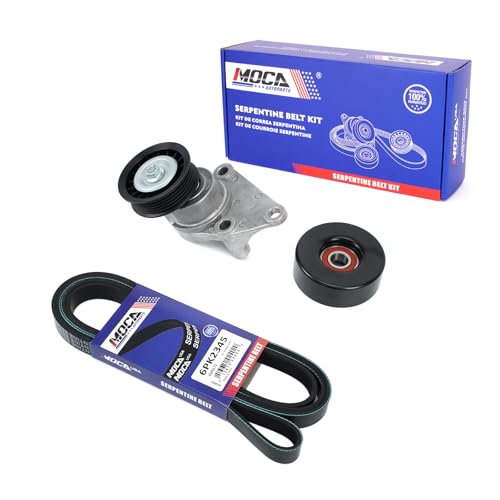
- Standard models with air conditioning require a 6-rib, 96.8-inch serpentine belt (Motorcraft JK6-968).
- Grooved pulleys contact the ribbed surface; the smooth water pump and idler pulley ride the belt back.
- The automatic tensioner uses internal spring loading—replace the assembly if indicator marks exceed standard travel limits.
- A squealing noise often signals an off-center idler pulley bearing or contaminated belt grooves.
- Belt replacement is fully DIY-accessible using a basic 1/2-inch breaker bar in under 30 minutes.
The front accessory drive system of the tenth-generation 1997 Ford F-150 equipped with the 4.6L Modular 2V V8 engine relies on a single serpentine belt to drive every primary engine accessory. Unlike earlier multi-belt configurations, the single serpentine setup maximizes mechanical efficiency, minimizes parasitic horsepower loss, and centralizes component drive load onto the crankshaft harmonic balancer. Precision routing is critical: an incorrectly routed belt can turn the reverse-rotation water pump the wrong way, leading to immediate overheating, or cause improper belt tensioner alignment that results in premature bearing failure across the front end accessory drive (FEAD) system.



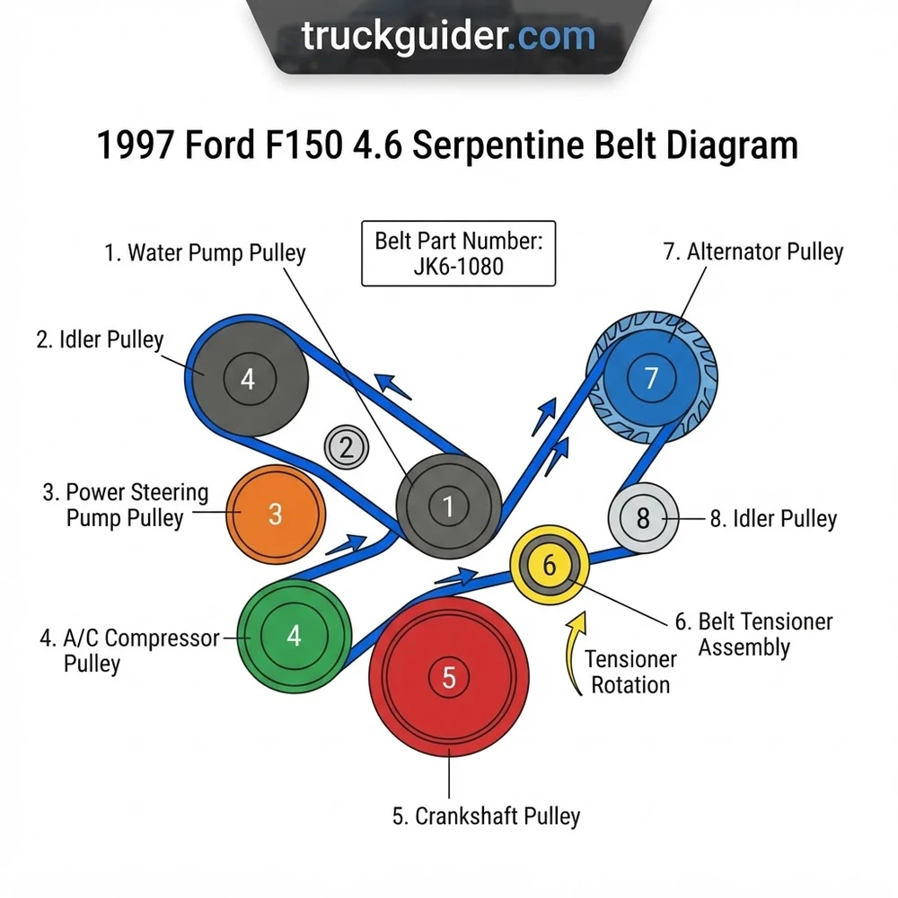
1997 Ford F150 4.6 Serpentine Belt Diagram and Pulley Layout

Understanding the pulley configuration on the 1997 Ford 4.6L (281 cubic inch) Triton V8 requires identifying each drive and driven accessory mounted to the front aluminum timing cover and block brackets. The 4.6L Modular engine features a 6-groove front end accessory drive system where smooth pulleys interface exclusively with the back (flat side) of the serpentine belt, while grooved pulleys interface directly with the ribbed side.
Crankshaft Pulley and Harmonic Balancer

Positioned at the bottom center of the block, the crankshaft harmonic balancer provides the driving force for the entire accessory system. It features a 6-groove profile machined into its outer perimeter, isolated from the inner hub by an elastomeric dampening ring. When diagnosing belt drive issues, inspect this dampening ring for dry rot, radial cracking, or axial separation, as harmonic balancer wobble will cause belt shredding and throw off alignment across the entire belt routing path.
Water Pump Pulley
The water pump sits high on the front cover, slightly offset toward the driver side of the engine centerline. The water pump pulley features a completely smooth surface because it runs off the flat, reverse side of the serpentine belt. Because the belt wraps under the water pump pulley after coming off the alternator, the pump operates in counter-clockwise (reverse) rotation relative to the crankshaft. Installing the belt over the top of this pulley rather than under it reverses coolant circulation, creating instantaneous cylinder head hot spots and severe engine overheating.
Alternator Pulley
Mounted high on the intake manifold valley bracket on the upper passenger side, the alternator is driven directly by a deep-groove 6-rib clutchless pulley. Its elevated position makes it the highest point in the serpentine belt loop. Because of the high rotational inertia of the alternator rotor, this pulley sustains substantial torsional load during transmission upshifts and sudden deceleration.
Power Steering Pump Pulley
Located on the lower driver side of the front timing cover, the power steering pump uses a pressed-on composite or steel grooved pulley. Proper pulley depth is paramount; if the pump has been replaced without using the correct pulley installer tool, an offset of even 1/16-inch will induce continuous belt chirping and edge-fraying. If you are completing a related service, refer to our F-150 power steering pump bleeding procedure to prevent hydraulic cavitation and pump bearing strain.
Idler Pulley and Accessory Locations
An auxiliary stationary idler pulley with a smooth surface is bolted to the front timing cover on the upper driver side between the power steering pump and the water pump. This idler increases the angle of belt wrap around both the power steering pump and water pump pulleys, ensuring continuous traction under peak hydraulic and cooling loads.
The 1997 4.6L engine was assembled in both Windsor (VIN code “6”) and Romeo (VIN code “W”) engine plants. While accessory locations remain virtually identical, Windsor engines often utilize an idler pulley with a 76mm diameter, whereas Romeo engines typically use an 80mm diameter smooth idler. Confirm idler diameter before purchasing replacement hardware.


1997 F150 4.6 Belt Size Specifications and OEM Belt Part Numbers
The 1997 Ford F-150 4.6L 2V Triton V8 utilizes standard SAE J1459 6-rib serpentine belts (profile PK). Factory dimensions vary primarily based on the presence of the factory air conditioning system and heavy-duty charging options. Selecting an incorrect belt length causes the spring-loaded automatic belt tensioner to ride against its internal mechanical stops, preventing proper dynamic tension control.
| Application / Equipment | OEM Part Number (Motorcraft) | Aftermarket Part Number | Belt Length (Effective / Pitch) | Width & Rib Count |
|---|---|---|---|---|
| 4.6L V8 with Air Conditioning (Standard FEAD) | JK6-968 (F65Z-8620-AA) | Gates K060966 / Dayco 5060968 | 96.8 inches (2459 mm) | 6 Ribs / 0.82 in (20.8 mm) |
| 4.6L V8 without Air Conditioning (Non-A/C) | JK6-825 (F65Z-8620-BA) | Gates K060825 / Dayco 5060825 | 82.5 inches (2095 mm) | 6 Ribs / 0.82 in (20.8 mm) |
| 4.6L V8 Ambulance / High-Output 130A Alternator | JK6-975 (F75Z-8620-AA) | Gates K060975 / Continental 4060975 | 97.5 inches (2476 mm) | 6 Ribs / 0.82 in (20.8 mm) |
| 4.6L V8 with A/C Delete Pulley Bracket Installed | JK6-968 (F65Z-8620-AA) | Gates K060966 / Bando 6PK2460 | 96.8 inches (2459 mm) | 6 Ribs / 0.82 in (20.8 mm) |
When measuring belt size, effective length refers to the circumference along the pitch line under operating load. Installing a 97.5-inch belt on a standard 96.8-inch specification will position the belt tensioner near its maximum travel stop, resulting in belt slip under heavy electrical or air conditioning loads. If servicing the primary charging hardware, consult the 1997 Ford F150 alternator replacement guide to ensure pulley offset matches factory alignment standards.
Factory Belt Tension Specification: Operating range is between 400 and 550 Newtons (90 to 123 lbs) dynamic tension when measured with a sonic tension meter across the span between the alternator and water pump.
1997 Ford F150 4.6 Belt Routing Path: Step-by-Step Installation
Threading the serpentine belt over the 1997 Ford F-150 4.6L FEAD assembly requires navigating tight clearances between the front timing cover, cooling lines, and the mechanical fan shroud. Follow this precise installation sequence to ensure correct alignment across all accessory pulleys.
- Clear the Engine Bay and Disconnect Battery Power: Disconnect the negative battery terminal to eliminate any risk of accidental cranking. Inspect the fan shroud assembly. While you can replace the belt without removing the mechanical fan, working space is limited. Ensure the cooling fan blades turn freely on the thermal viscous fan clutch.
- Feed the Belt Past the Mechanical Fan Blades: Take the new serpentine belt, compress it into a narrow loop, and slide it down between the top edge of the fan shroud and the mechanical fan blades. Work the loop over each individual fan blade one at a time until the entire circumference of the belt sits completely behind the fan clutch assembly, resting loosely over the water pump and crankshaft hub.
- Anchor Across the Crankshaft Harmonic Balancer: Route the grooved side of the belt around the bottom of the crankshaft pulley. Ensure all six ribs seat squarely in the balancer grooves. Maintain upward tension by hand so the belt does not jump out of the lower tracks.
- Route Downward to the A/C Compressor Pulley: Carry the passenger-side run of the belt downward and wrap it around the grooved A/C compressor pulley situated low on the front passenger side. The ribs must seat flush within the compressor clutch plate tracks.
- Wrap the Tensioner and Upward to the Alternator: Feed the belt upward from the A/C compressor and route the back (smooth side) of the belt over the automatic belt tensioner pulley. Take the remaining loop from the tensioner and pull it over the top of the alternator pulley located at the top center-passenger side of the motor. The grooved side must rest inside the alternator pulley grooves.
- Loop the Lower Driver Side Accessories: On the driver side, bring the belt down around the grooved power steering pump pulley. Route the belt back upward and around the stationary smooth idler pulley. The flat backside of the belt rides directly against the smooth face of this idler.
- Retract the Tensioner and Slip Over the Water Pump: Insert a 1/2-inch drive breaker bar into the tensioner arm square receiver. Rotate the tensioner firmly counter-clockwise (toward the passenger side fender) to compress the internal spring. With maximum slack created, slide the smooth back of the belt underneath the smooth water pump pulley. Slowly release the breaker bar until the tensioner arm makes contact with the belt and applies operating load.
- Inspect Final Rib Engagement: Use an inspection mirror and shop light to examine every grooved pulley (crankshaft, A/C compressor, alternator, and power steering). The belt ribs must not sit elevated on pulley shoulders or overhang outside flanges. A single misaligned rib will shear off longitudinally within minutes of startup.
Never route the belt over the top of the water pump pulley. The 4.6L Modular water pump impeller is engineered exclusively for counter-clockwise rotation driven by the back of the belt. Routing over the top spins the pump clockwise, inducing zero cooling flow and causing catastrophic overheating within 5 miles.
Belt Tensioner Operation and Tension Adjustment Notes for 4.6L V8
The 1997 Ford 4.6L uses a cast-aluminum, spring-loaded automatic belt tensioner positioned on the passenger-side front timing cover. Unlike manual mechanical brackets, this internal torsional coil spring dynamically dampens belt vibration and automatically compensates for thermal expansion and standard belt stretch over time.
The tensioner housing features a 1/2-inch square drive tool receiver broached directly into the cast swing arm. Do not use open-ended wrenches on the pulley bolt head to release tension; this risks rounding off the center bolt or damaging the sealed bearing assembly. Instead, use a low-profile 1/2-inch drive serpentine belt tensioner tool or an 18-inch breaker bar. Rotating the tool counter-clockwise swings the tensioner arm toward the passenger side, releasing tension across the entire front drive belt routing path.


Inspect the cast alignment indicator marks on the base of the tensioner housing. The housing features three cast ribs: a center nominal reference mark and two outer limit stops. When a new belt of correct OEM belt size is properly routed, the raised indicator pointer on the moving arm should align directly between the center nominal mark and the minimum-stretch mark.
If the pointer rests on or past the maximum extension stop, the belt has sustained significant elongation or an oversized belt part number has been installed. Conversely, if the tensioner pointer sits directly on the lower mechanical stop, the belt is too short, which places excessive radial load on the alternator and water pump front bearings, inducing premature bearing seizure.
If the tensioner arm exhibits excessive flutter (oscillating more than 1/4 inch during engine idle), the internal dampening mechanism has failed. Replace the tensioner assembly as a unit. Tighten the single central mounting bolt to factory specification: 35 to 46 lb-ft (47 to 62 Nm). When rebuilding front cover hardware, refer to the Triton 4.6L timing chain replacement walkthrough for detailed front-cover bolt torque patterns and fastener dimensions.
1997 Ford F150 4.6 Serpentine Belt Diagram Variations: 5.4L and A/C
While the 4.6L Modular V8 was the standard V8 in 1997, Ford also offered the 4.2L Essex OHV V6 and the taller 5.4L Triton Modular V8. Because these engines share several chassis mounting configurations, technicians frequently confuse belt dimensions and pulley routing schemes.
The 5.4L Triton engine utilizes a raised engine block deck height compared to the 4.6L (deck height of 10.079 inches on the 5.4L vs. 8.937 inches on the 4.6L). This 1.142-inch increase in deck height widens the overall distance between the cylinder heads and crankshaft. As a result of this deck engagement geometry, the 5.4L accessory drive spreads the alternator and upper idler pulleys further apart, requiring a significantly longer serpentine belt (typically 99.0 inches on the 5.4L compared to 96.8 inches on the 4.6L). Attempting to force a 4.6L belt onto a 5.4L engine will result in complete tensioner lock-up or an inability to clear the final pulley.
The 4.2L Essex V6 engine uses a completely distinct 90-degree pushrod block architecture with a reverse-mounted power steering pump and an independent idler layout, utilizing an 82.5 to 83.5-inch belt that is non-interchangeable with any Modular V8 configuration.
| Engine Configuration | Key Pulley Differences | Belt Length Range | Routing Distinction |
|---|---|---|---|
| 4.6L V8 (With A/C) | 76mm or 80mm smooth idler; low-deck timing cover | 96.8 in (2459 mm) | Standard dual-bank loop under smooth water pump |
| 4.6L V8 (Without A/C) | A/C compressor replaced by idler bracket or omitted | 82.5 in (2095 mm) | Bypasses lower passenger accessory bracket completely |
| 5.4L V8 (With A/C) | Tall-deck block; higher alternator placement | 99.0 in (2515 mm) | Identical pulley count, wider spatial spread across heads |
| 4.2L V6 (With A/C) | Pushrod V6 timing cover; passenger-side tensioner swing | 83.0 in (2108 mm) | Belt routes directly over water pump hub with reversed idlers |
For trucks built without factory air conditioning, Ford implemented two distinct strategies. Fleet vehicles without A/C often used a direct-route belt (82.5 inches) that eliminated the lower passenger-side accessory run entirely. However, retail base models commonly received an A/C bypass idler pulley bracket bolted directly into the original A/C compressor mounting lugs. When an A/C bypass pulley is installed, the truck retains the standard 96.8-inch serpentine belt and follows the identical belt routing path as an air-conditioned model.



1997 Ford F150 4.6 Serpentine Belt Diagram Questions Answered
How do I identify if the tensioner or idler pulley bearing is failing?
Remove the serpentine belt to isolate front accessory drive friction. Spin the idler pulley and tensioner pulley by hand. Both should rotate smoothly with light internal hydraulic resistance from their synthetic grease packing. If a pulley spins freely like a skateboard wheel, emits a metallic grinding hiss, or exhibits radial play (rocking movement when pushed side-to-side along the shaft), the sealed bearing has dried out or degraded. Under engine operation, a failing bearing typically generates a high-pitched metallic whine that changes directly with engine RPM, irrespective of electrical or steering loads.
Can a stretched serpentine belt cause charging or air conditioning issues?
Yes. When the serpentine belt stretches past the dynamic travel limit of the tensioner, normal belt surface pressure against the smaller-diameter pulleys drops significantly. The alternator and A/C compressor pulleys have the smallest contact surface areas and the highest torque resistance. When the belt slips across these drive surfaces, the alternator will undercharge under load (dimming headlights at idle), and the A/C compressor clutch will slip, resulting in elevated high-side head pressures, clutch plate overheating, and warm cabin air.
What is the correct tool to retract the 1997 Ford F-150 4.6L belt tensioner?
The factory 4.6L Modular belt tensioner requires a 1/2-inch square drive tool inserted directly into the square broach on the casting. While an 18-inch standard breaker bar often fits, clearance between the front cover and the radiator fan shroud can be restrictive. A dedicated flat serpentine belt tensioner tool provides the slim profile required to maximize rotational swing without contacting the fan blades. Never attempt to loosen or lever the tensioner using the 13mm or 15mm bolt that secures the pulley wheel to the tensioner arm, as this can snap the fastener or strip its threads.
Why does my new serpentine belt squeal immediately after installation?
Immediate belt squeal following replacement is almost universally caused by accessory pulley misalignment rather than a defective belt. Inspect the power steering pump pulley to confirm it is pressed fully flush to the pump shaft. Furthermore, verify that the belt ribs are seated down in the valleys of every grooved pulley rather than riding elevated on a guide shoulder. Finally, check for oil or coolant contamination on smooth pulleys; fluids glazing the back of the belt cause continuous chirping as it wraps under the smooth water pump pulley.