2010 Ford F150 Serpentine Belt Diagram: Routing Guide 2026

On the 2010 Ford F-150 (4.6L/5.4L V8), route the serpentine belt ribbed-side around the crankshaft, alternator, power steering, and AC compressor pulleys. Loop the smooth back over the water pump and idler pulley. Rotate the automatic belt tensioner counterclockwise using a 1/2-inch breaker bar to slip the belt over the final idler.
📌 Key Takeaways
- The 5.4L 3V engine uses an automatic belt tensioner requiring a 1/2-inch square drive breaker bar.
- Check engine code: 4.6L 2V, 4.6L 3V, and 5.4L 3V utilize distinct pulley diagram layouts and belt lengths.
- Torque the idler pulley bolt to 18-22 lb-ft (25-30 Nm) and the belt tensioner bolt to 35 lb-ft (47 Nm).
- Worn tensioner dampeners or misaligned idler pulleys are the primary causes of squeal and premature edge fraying.
- Replace drive belts every 60,000 to 90,000 miles, or immediately if transverse cracking exceeds 3 cracks per inch.
Accurate Front Engine Accessory Drive (FEAD) servicing on the eleventh-generation and early twelfth-generation Ford full-size trucks requires precise comprehension of component placement, belt wrap angles, and tension requirements. The 2010 model year marks a transitional point in the Ford truck powertrain lineup, representing the final production year of the legendary 4.6L and 5.4L Modular V8 architectures alongside the limited-run introductory rollout of the 6.2L Boss V8 in the SVT Raptor. Installing or diagnosing a drive belt on these powertrains requires absolute adherence to factory routing paths, pulley groove alignments, and dynamic tension specifications to avoid premature bearing failure, belt slip, or thrown belts under heavy load.
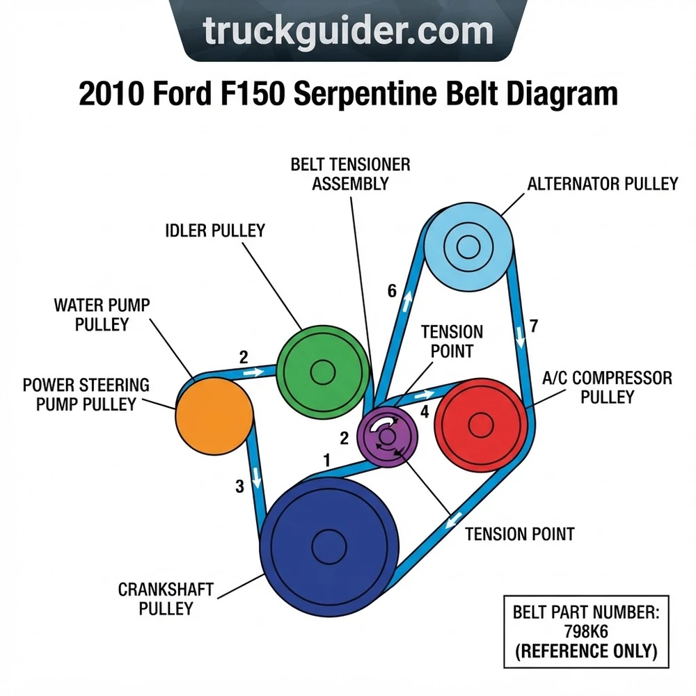
2010 Ford F150 Serpentine Belt Diagram by Engine Configuration



Every engine option fitted to the 2010 Ford F-150 utilizes a dedicated Front Engine Accessory Drive (FEAD) configuration. Understanding the specific pulley diagram for your truck’s engine displacement is critical, as belt lengths, wrap orientations, and idler counts differ markedly across engine families.



Ford 5.4L 3V Triton V8 FEAD Pulley Layout


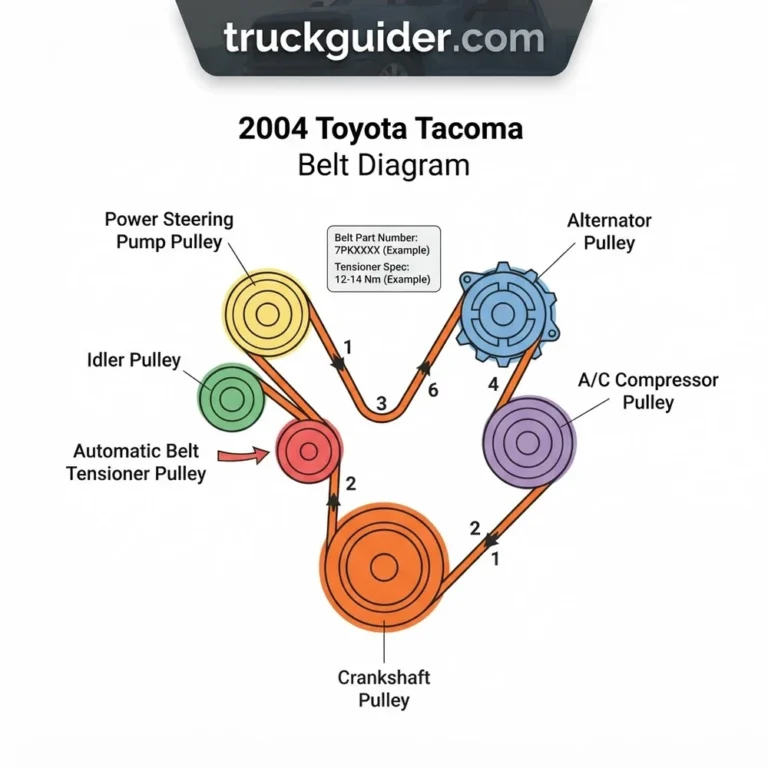
The 5.4L 3-Valve SOHC Triton V8 (VIN code V) utilizes a comprehensive single 6-rib serpentine belt drive arrangement that powers all primary accessories. As shown in the diagram above, the drive system relies on the central crankshaft pulley (integrated into the harmonic balancer) at the bottom center to drive the entire loop. Moving clockwise from the crankshaft pulley:
- The belt travels upward on its ribbed side over the grooved water pump pulley situated in the center of the engine timing cover.
- From the water pump, the belt extends upward toward the passenger-side mounted high-output alternator pulley (grooved).
- Exiting the alternator, the flat backside of the belt wraps under a smooth, stationary upper idler pulley that sets the alternator wrap angle.
- The belt spans across the engine valley toward the driver side, passing around the lower grooved power steering pump pulley.
- From the power steering pump, the ribbed side engages the lower-driver-side air conditioning (A/C) compressor clutch pulley.
- Leaving the A/C compressor, the smooth backside of the belt wraps around the dynamic belt tensioner pulley, which exerts constant outward, spring-loaded force to maintain factory tension specifications.
- Finally, the belt completes the loop by running beneath a secondary smooth idler pulley before returning to the grooved crankshaft pulley.
Ford 4.6L 2V and 3V V8 Belt Routing Path Variations
The 2010 model year offered two distinct variants of the 4.6L Modular engine: the standard 2-Valve SOHC (VIN code W) paired with the 4R75E 4-speed transmission, and the higher-output 3-Valve SOHC (VIN code 8) mated to the 6R80 6-speed transmission. While both share identical block deck heights, their accessory bracketry and front timing covers demand careful attention to the belt routing path.
On the 4.6L 2V, the FEAD is shared largely with the previous generation F-150 platform. The routing path loops directly from the crankshaft pulley over the water pump pulley, up to the alternator, under a single stationary idler, around the power steering pump pulley, across the dynamic tensioner, down to the A/C compressor, and back to the crank. The 4.6L 3V shares its front cover profile with the 5.4L 3V, utilizing an auxiliary idler pulley located between the tensioner and the lower accessories to increase the deck engagement and contact surface across the crankshaft dampener.
Ford 6.2L Boss V8 Serpentine Belt Diagram Geometry
Late in the 2010 model year, Ford introduced the 6.2L SOHC 2-Valve Boss V8 exclusively in the F-150 SVT Raptor. The 6.2L architecture departs entirely from the Modular family, featuring a wider bore spacing, an aluminum front cover, and an offset dynamic tensioner assembly. The 6.2L utilizes a heavy-duty 6-rib serpentine belt routing path designed for high-RPM stability. The crankshaft pulley drives an overhead water pump via the grooved face, routes outward to an alternator mounted high on the driver side, transitions over an upper smooth idler, drops to a cast-iron bracketed power steering pump, rounds the low-mount A/C compressor, and runs through an inverted-pivot belt tensioner assembly.


2010 F150 Serpentine Belt Part Number and Size Guide



Installing an incorrect belt size on a 2010 F-150 leads to dynamic tensioner bottoming, belt squeal, or accessory underdrive conditions. Ford factory specifications require high-tensile EPDM (Ethylene Propylene Diene Monomer) construction for superior thermal resistance and crack prevention. Below are the OEM belt specifications and verified cross-references across all factory engine offerings.
| Engine Displacement | OEM Belt Part Number | Aftermarket Part Number | Rib Count & Profile | Effective Belt Size (Length) |
|---|---|---|---|---|
| 4.6L 2V V8 (VIN W) | Motorcraft JK6-1015 (7L3Z-8620-B) | Gates K061015 / Dayco 5061015 | 6-Rib, PK Profile | 101.5 in (2578 mm) |
| 4.6L 3V V8 (VIN 8) | Motorcraft JK6-1020 (AL3Z-8620-B) | Gates K061020 / Continental 4061020 | 6-Rib, PK Profile | 102.0 in (2591 mm) |
| 5.4L 3V Triton V8 (VIN V) | Motorcraft JK6-1025-A (AL3Z-8620-A) | Gates K061025 / Bando 6PK2605 | 6-Rib, PK Profile | 102.5 in (2604 mm) |
| 6.2L Boss V8 (VIN 6) | Motorcraft JK6-879 (AL3Z-8620-C) | Gates K060879 / Dayco 5060880 | 6-Rib, PK Profile | 87.9 in (2233 mm) |
According to OEM specs, the 2010 Ford F-150 equipped with high-amp dual-alternator or commercial snowplow packages uses an extended 103.2-inch belt (Motorcraft JK6-1032). Measure the original belt outside circumference before installing an aftermarket replacement if your truck features heavy-duty fleet electrical packages.
Step-by-Step 2010 Ford F150 Serpentine Belt Routing Path Installation


Replacing the drive belt on the 2010 F-150 requires systematic execution to avoid damaging the composite fan shroud, the water pump pulley flange, or the dynamic belt tensioner stop. Follow these sequential mechanical instructions to replace the belt safely and accurately.
Pre-Installation Safety Protocols and Tool Staging


Park the vehicle on a level surface, shift the transmission into Park, set the emergency brake, and disconnect the negative battery cable with an 8mm wrench to prevent accidental starter engagement. You will need a dedicated serpentine belt tensioner tool or a long-handled 1/2-inch drive breaker bar, a 10mm socket for shroud hardware (if optional removal is preferred for access), an inspection mirror, and an LED work light.



De-Tensioning the System and Removing the Worn Belt
- Locate the automatic spring-loaded tensioner positioned on the lower passenger side (for 5.4L/4.6L) of the front timing cover. Inspect the tensioner body to locate the 1/2-inch square drive female receiver cast directly into the dynamic tensioner arm.
- Insert the male square drive of the serpentine belt tensioner tool directly into the receiver hole, ensuring full engagement to avoid rounding the cast aluminum opening.
- Rotate the tensioner tool clockwise (toward the driver side) against the internal spring resistance. Maintain continuous pressure on the tool to relieve dynamic tension from the belt loop.
- While holding the tensioner in the fully compressed position, slip the belt off the smooth, ungrooved water pump pulley first. The water pump pulley lacks retaining shoulders, making it the easiest release point.
- Gently allow the tensioner arm to rotate back counter-clockwise until its internal stop rests against the housing. Never let the tensioner arm snap back unassisted, as doing so fractures the cast aluminum body.
- Unthread the belt from around the crankshaft pulley, harmonic balancer, power steering pump, A/C compressor, and alternator, then feed it around the cooling fan assembly to extract it from the engine bay.
Do not use an open-ended wrench or standard socket on the tensioner pulley center bolt to relieve spring tension. Doing so risks shearing the pulley mounting bolt or stripping the internal threads in the timing cover casting.
Threading the New Serpentine Belt from the Crankshaft Upward
- Carefully work the new OEM belt over the mechanical engine fan blades one blade at a time, keeping the belt free of grease or oil.
- Route the belt onto the lower grooved crankshaft pulley first, ensuring that all 6 ribs align dead-center into the pulley tracks on the harmonic balancer.
- Route the lower run of the belt toward the driver side, seating the grooved side around the A/C compressor pulley and the power steering pump pulley.
- Loop the belt around the stationary idler pulley (smooth side contacting the pulley bearing surface) and route the top loop across the engine timing cover to the alternator pulley on the upper passenger side.
- Route the belt around the ribbed surface of the dynamic belt tensioner pulley, leaving the final slack positioned adjacent to the smooth water pump pulley.
Final Seating and Tensioner Release Sequence
- Engage the 1/2-inch drive tensioner tool into the tensioner arm and rotate clockwise to maximum deflection.
- Slide the smooth backside of the belt under the smooth lip of the water pump pulley.
- Slowly release the tensioner tool, allowing the dynamic spring to take up drive slack.
- Use an inspection mirror to visually verify that the belt is seated entirely within the grooves of the crank, alternator, A/C, and power steering pulleys. A single misaligned rib will cause immediate belt shredding upon startup.
- Reconnect the negative battery terminal, initiate engine startup, and observe FEAD track alignment at idle for 60 seconds.
Belt Tensioner Operation and Tension Adjustment Notes


The 2010 Ford F-150 relies on a fully automatic spring-loaded tensioner engineered by Litens for Ford Motor Company. Unlike manual systems requiring manual deflection gauges, this assembly compensates dynamically for thermal expansion, engine torsional vibration, and structural belt stretch over time.
The dynamic tensioner features cast indicator marks on the base and arm. When a new belt is installed, the alignment indicator must rest between the minimum and maximum wear marks. If the indicator extends past the maximum stop, the belt has stretched beyond service limits or an incorrect belt size was installed.
Tensioner Spring Dynamics and Mechanical Travel Range


The internal torsional flat spring maintains an operating belt tension range of 350 to 450 N (78 to 101 lbf) under normal running conditions. As rotational load surges—such as when the A/C magnetic clutch engages or the power steering pump hits maximum system pressure (1,400 to 1,550 PSI at full steering lock)—the tensioner pivots dynamically to dampen belt oscillation. If the internal hydraulic damping fluid leaks or the pivot bushing binds, the tensioner arm oscillates violently, generating high-frequency belt chatter and accelerated wear across the idler pulley bearings.
Diagnosing Bearing Wear on the Belt Tensioner Pulley and Idler Pulley
Whenever removing the serpentine belt, complete a manual mechanical inspection of every rotating component in the FEAD system. Spin the belt tensioner pulley and each idler pulley by hand while listening and feeling for the following symptoms:
- Bearing Roughness: Any gritty tactile feedback or perceptible roughness indicates breakdown of the internal polyurea grease within the sealed deep-groove 6203 ball bearing.
- Radial and Axial Play: Grasp the outer perimeter of the pulley and push/pull along the axis. Axial runout exceeding 0.030 inches (0.76 mm) requires immediate pulley replacement.
- Surface Grooving: Inspect smooth idler pulleys for uneven polymer wear or dishing. A concave smooth pulley causes the belt to wander laterally across adjacent grooved pulleys.
- Tensioner Arm Deflection: Inspect the tensioner arm under load with the engine idling. Oscillation exceeding 1/4 inch (6.35 mm) indicates failed internal damping, necessitating replacement of the complete dynamic tensioner assembly (OEM Motorcraft BT-101 / AL3Z-6B209-A).
2010 Ford F-150 Belt Routing Diagram vs Other Model Years
Significant architectural changes define the front engine accessory drives across F-150 generations. Technicians must avoid applying 2004–2008 Modular procedures or 2011+ Gen 1 Coyote procedures to the 2010 model year. The table below outlines structural FEAD differences critical for proper component ordering and routing verification.


| Architecture Parameter | 2004–2008 (11th Gen F-150) | 2010 (Transition Model Year) | 2011–2014 (12th Gen Modern) |
|---|---|---|---|
| Primary V8 Engines | 4.6L 2V / 5.4L 3V Modular | 4.6L 2V/3V / 5.4L 3V / 6.2L Boss | 3.7L V6 / 5.0L Coyote / 3.5L EcoBoost |
| Steering System Drive | Hydraulic Power Steering Pump Pulley | Hydraulic Power Steering Pump Pulley | EPAS (Electric Power-Assist Steering; No Pump) |
| Belt Configuration | Single 6-Rib Serpentine Drive | Single 6-Rib (Modular) / Dual on 6.2L | Dual-Belt Layout (Stretchy A/C + Primary) |
| Tensioner Drive Interface | 1/2-Inch Square Female Receiver | 1/2-Inch Square Female Receiver | 15mm Cast Hex Lug or 3/8-Inch Square |
| Average Belt Length | 102.0 – 102.5 in | 101.5 – 102.5 in | Main: 49.5–51.2 in / A/C: 35.8 in |
The defining technical distinction occurs between 2010 and 2011. While the 2010 truck retains a conventional hydraulic power steering pump integrated into the main accessory loop, the 2011 redesign adopted Electric Power-Assist Steering (EPAS) on all platforms except the 6.2L. This eliminated the hydraulic pump pulley entirely, transitioning the platform to a split-belt drive system with a primary accessory belt and a dedicated stretch-fit belt for the A/C compressor.
2010 Ford F150 Serpentine Belt Diagram Questions Answered
How can you tell if the 2010 F150 serpentine belt needs replacement?
Modern EPDM serpentine belts do not crack as readily as older neoprene belts. Instead, they lose rib material via friction wear. Measure belt wear using an EPDM rib depth gauge. If the rib profile has eroded more than 1/32-inch (0.8 mm) or the belt shows signs of edge fraying, oil saturation, rib chunking, or backing separation, replace the belt immediately. High-pitched squealing under load indicates belt glazing or tension loss.
What tool is required to relieve tension on the 2010 F-150 belt tensioner?
The automatic belt tensioner on the 2010 Ford F-150 Modular V8 engines (4.6L and 5.4L) features a 1/2-inch square female drive slot cast directly into the tensioner body. A standard 1/2-inch drive long-handled breaker bar or a low-profile ratcheting serpentine belt tensioner tool fits directly into the unit. Space between the cooling fan clutch and the front cover is limited, making thin-profile dedicated belt tools superior to standard ratchets.
Can you route the 5.4L 3V belt over the water pump pulley incorrectly?


Yes. Routing errors on the water pump are among the most common installation mistakes on this engine. The water pump pulley is a completely smooth steel pulley that runs on the flat back side of the serpentine belt. If you route the grooved face of the belt over the smooth water pump pulley, or under it instead of over, the water pump rotates in reverse or experiences insufficient surface grip, triggering rapid engine overheating and cooling system cavitation within minutes.
Why does the belt slip or squeal after installing a new alternator or A/C compressor?
Pulley misalignment is the leading cause of new belt squeal. When installing a replacement alternator, A/C compressor, or power steering pump, check that the new accessory pulley matches the exact offset and deck engagement of the factory unit. Even a 1/16-inch (1.5 mm) axial offset forces the belt to enter the adjoining pulley at an angle, causing belt chirp. Verify pulley alignment across all pulleys using a laser alignment tool or straightedge placed across the harmonic balancer face.
Does the 2010 Ford F-150 5.4L have an under-hood belt diagram sticker?
Factory-built 2010 F-150s originally came with a vehicle emission control and belt routing path decal affixed to the top of the plastic radiator core support or upper fan shroud. However, on vehicles over a decade old, this sticker is frequently unreadable, peeled, or missing due to front-end collision repairs or thermal degradation. Always rely on the factory pulley diagram specs detailed in this guide rather than unverified generic diagrams.