2013 Ford F150 5.0 Serpentine Belt Diagram: Routing Guide 2026

The 2013 Ford F-150 5.0L Coyote engine uses a dual-belt system. The main accessory drive belt routes ribbed-side over the crankshaft, water pump, and alternator, running smooth-side across the idler pulley and automatic belt tensioner. Releasing tension requires rotating the 3/8-inch tensioner arm counterclockwise. A secondary bottom stretch belt drives the A/C compressor.
📌 Key Takeaways
- Main drive belt uses a 6-rib design measuring 51.1 inches (Motorcraft JK6-511-A).
- The 5.0L Coyote features Electric Power Steering (EPAS), omitting a hydraulic steering pump from the pulley diagram.
- The automatic belt tensioner requires a standard 3/8-inch drive breaker bar with no manual torque adjustment needed.
- Failing to install the separate A/C stretch belt using the proper installer tool often damages compressor seals.
- DIY installation takes under 45 minutes; seek professional help if tensioner arm indicator marks sit outside normal limits.
Navigating the dual-belt accessory drive on Ford’s modular 5.0L Coyote V8 requires a precise understanding of component placement, belt path routing, and tensioning mechanisms. The 2013 Ford F-150 5.0L front-engine accessory drive (FEAD) differs significantly from previous modular 4.6L and 5.4L Triton platforms. Most notably, Ford eliminated the traditional hydraulic power steering pump in favor of an Electric Power-Assisted Steering (EPAS) rack mounted directly to the subframe. As a result, the primary serpentine belt operates in a simplified loop driving the water pump and alternator, while a secondary stretch-fit belt powers the air conditioning compressor. This technical guide outlines the complete 2013 ford f150 5.0 serpentine belt diagram, belt specifications, removal and installation procedures, and diagnostic metrics to maintain proper drive system performance.
2013 Ford F-150 5.0L Coyote V8 FEAD Pulley Layout & Dual-Belt Routing Path
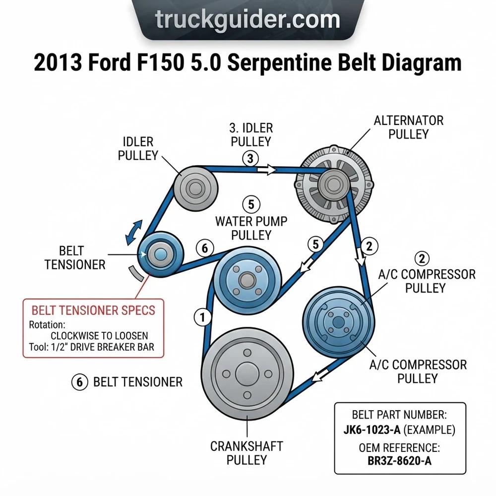
2013 Ford F150 5.0 Serpentine Belt Diagram and Pulley Layout




The 2013 Ford F-150 equipped with the 5.0L 4-valve DOHC Coyote V8 utilizes a split-drive accessory system. The front of the engine block houses five primary rotating interfaces on the main accessory drive, complemented by a dedicated two-point circuit for the air conditioning system. Because the 5.0L utilizes EPAS, the traditional high-load hydraulic pump pulley is absent, reducing parasitic drag and altering the wrap angles across the remaining accessory pulleys.



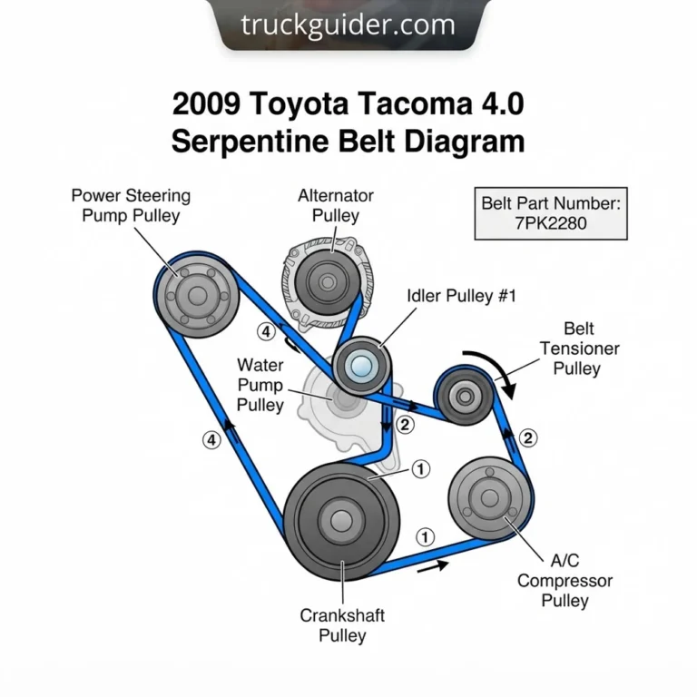
To interpret the 2013 ford f150 5.0 serpentine belt diagram correctly, you must distinguish between drive (powered) and driven (accessory/idler) components across both drive planes:
- Crankshaft Pulley (Harmonic Balancer): The harmonic balancer features a dual-stepped outer ring with two distinct belt tracks. The rearward (inboard) 4-rib track drives the A/C compressor, while the forward (outboard) 6-rib track drives the main accessory serpentine belt. The balancer is keyed to the crankshaft snout and dampened with vulcanized rubber to absorb torsional crankshaft vibration.
- Water Pump Pulley: Positioned high and central on the front timing cover. Unlike the crankshaft and alternator, the water pump uses a smooth, non-grooved pulley. The back (smooth side) of the 6-rib serpentine belt rides over this pulley, driving the water pump impeller in a reverse rotation relative to crankshaft rotation.
- Alternator Pulley: Located on the lower driver (left) side of the engine block. The alternator features a 6-groove pulley designed to match the ribbed interior of the serpentine belt. It accepts continuous rotational power directly from the water pump run.
- Automatic Belt Tensioner: Mounted on the front engine timing cover on the upper driver side, between the water pump and the alternator loop. The tensioner assembly consists of an internal torsion spring, a mechanical swing arm, and a smooth idler pulley. The back of the belt engages this pulley to maintain dynamic running tension.
- Upper Idler Pulley: Positioned adjacent to the tensioner on the upper engine face. This grooved guide pulley establishes the proper belt entry angle into the crankshaft pulley, preventing harmonic belt whip under sudden throttle transitions.
- A/C Compressor Pulley: Located on the lower passenger (right) side of the block. Driven exclusively by the inner 4-rib stretch belt off the harmonic balancer’s inboard track, completely bypassed by the primary belt circuit.
Reviewing a related Ford F-150 Coyote cooling system diagram reveals that the smooth water pump pulley requires reverse rotation to generate targeted coolant flow through the cylinder heads. Routing the ribbed surface across the water pump will reverse flow dynamics and induce rapid overheating.
OEM Belt Part Numbers and Belt Sizes for the 5.0L Coyote



The 2013 5.0L F-150 engine requires two dedicated belts engineered to strict dimensional tolerances. Modern OEM belts are manufactured from Ethylene Propylene Diene Monomer (EPDM) synthetic elastomer compounds. EPDM provides thermal stability up to 150°C (302°F) and structural resistance to oil exposure, rib shearing, and ozone cracking. When replacing belts, verify the rib profile and effective length to avoid improper tensioner displacement or stretch belt throw-off.
| Drive Circuit | OEM Motorcraft Part # | Ford Base Engineering # | Rib Count | Effective Length | Aftermarket Reference |
|---|---|---|---|---|---|
| Main Accessory Drive | JK6-508-A | BR3Z-8620-R | 6-Rib | 50.8 in (1290 mm) | Gates K060508 / Continental 4060508 |
| A/C Compressor Drive | JK4-377 | BL3Z-8620-B | 4-Rib (Stretch) | 37.7 in (958 mm) | Gates K040377SF / Dayco 4PK958S |
The main accessory drive uses a standard tensioned 6-rib belt profile, whereas the A/C compressor system relies on a self-tensioning stretch-fit belt. The A/C belt possesses an elastic polyamide tensile cord embedded inside the EPDM substrate, designed to maintain dynamic tension without an external mechanical tensioner. Never substitute a standard mechanical-tension 4-rib belt onto the A/C circuit; standard tensile cords lack elasticity and will shear during installation or overload the compressor front snout bearings.
Installation of the 4-rib A/C belt requires a universal Stretch Belt Installation Tool (such as OTC 5968 or Gates SFT001). This tool clamps to the harmonic balancer lip to guide the elastic ribs into the inner pulley track as the crankshaft is manually rotated.


2013 Ford F-150 5.0 Serpentine Belt Routing Path and Installation


Replacing both belts on the 2013 Ford F-150 5.0L requires addressing the structural obstruction created by the forward belt plane. Because the main 6-rib accessory belt sits outboard of the A/C belt on the harmonic balancer, the main accessory belt must be removed first, regardless of whether you are servicing the main drive or only replacing the A/C compressor belt.
Disconnect the negative battery terminal before servicing the FEAD system. Because the cooling fan assembly and high-current alternator terminal sit in direct proximity to the tensioner sweep area, accidental ignition activation presents severe entanglement and electrical short risks.
Step 1: Front Engine Access and Preparation


Position the vehicle on level ground, engage the parking brake, and disconnect the negative terminal on the battery. Unclip the upper radiator air deflector and remove the air intake duct running from the airbox to the throttle body using an 8mm socket. If working from beneath, remove the lower composite splash shield to expose clear access to the crankshaft pulley and lower A/C compressor assembly.
Step 2: Main Accessory Belt Removal
Locate the automatic belt tensioner on the driver side of the engine block. Insert a 3/8-inch drive breaker bar or a low-profile serpentine belt tool directly into the square drive opening cast into the tensioner arm. Rotate the breaker bar clockwise (toward the passenger side) against internal spring pressure to rotate the tensioner pulley downward and relieve belt tension. While holding the arm in this retracted position, slip the slackened belt off the smooth water pump pulley, then slowly release the breaker bar until the internal stop rests. Slide the belt off the alternator, crankshaft, and idler pulley, feeding it around the cooling fan blades to remove it from the engine bay.



Step 3: A/C Stretch Belt Removal
The factory A/C belt on the inner crankshaft pulley track lacks a mechanical tensioner. Ford service manuals direct technicians to cut the old A/C belt with shop shears if a new belt is being installed. If the belt must be removed without destruction for auxiliary component servicing, mount a stretch belt removal tool onto the inboard harmonic balancer rim. Place an 18mm socket and heavy-duty ratchet on the center harmonic balancer bolt. Rotate the crankshaft clockwise while guiding the removal wedge under the belt to derail the 4-rib belt forward off the compressor track.
Step 4: A/C Stretch Belt Installation


Clean the inner 4-rib track of both the crankshaft pulley and the A/C compressor pulley with brake cleaner to remove rubber dust and oil residues. Loop the new stretch belt (Motorcraft JK4-377) over the lower grooved track of the A/C compressor pulley. Mount the magnetic or bolt-on stretch belt installation tool to the outer face of the harmonic balancer’s inner track at roughly the 10 o’clock position. Feed the top loop of the stretch belt onto the tool. Using an 18mm socket on the center crankshaft bolt, rotate the engine clockwise. The tool forces the elastic belt over the balancer outer flange, seating the ribs into the inner groove. Rotate through 360 degrees to confirm that all 4 ribs sit fully engaged in both pulley tracks without rib overlap.
Step 5: Main Accessory Belt Routing Path
Refer to the 2013 ford f150 5.0 serpentine belt diagram layout to establish proper belt routing. Begin by threading the new 6-rib belt (Motorcraft JK6-508-A) around the forward track of the crankshaft pulley, ensuring the ribbed surface mates flush with the pulley channels. Trace the belt upward:
- Route the left side of the belt around the upper grooved idler pulley.
- Loop the belt underneath the grooved alternator pulley on the lower driver side.
- Route the belt upward toward the tensioner, running the smooth back of the belt across the automatic tensioner pulley face.
- Leave the smooth water pump pulley as the final installation point.
Step 6: Final Tensioning and Verification
Attach the 3/8-inch drive breaker bar to the automatic tensioner drive socket. Rotate the tensioner clockwise to maximum travel. With your free hand, slide the smooth back of the belt under the smooth water pump pulley. Slowly release the tensioner arm, ensuring the belt does not jump out of the grooved tracks on the alternator, idler, or crankshaft. Visually verify alignment from above and below: all belt ribs must seat dead-center inside their matching pulley grooves.


Crankshaft Pulley Center Bolt: 18mm hex head (Rotate clockwise only during service). Main Tensioner Retaining Bolt Torque: 40 Nm (30 lb-ft). Upper Grooved Idler Pulley Bolt Torque: 25 Nm (18 lb-ft).
Automatic Belt Tensioner Operation and Pulley Deck Engagement


The automatic belt tensioner on the 5.0L Coyote engine serves two critical operational roles: dampening accessory load harmonics and compensating for dynamic belt elongation over runtime. The internal mechanical torsion spring applies constant radial force through the tensioner arm, pressing the smooth pulley against the back surface of the main serpentine belt.
Reading Tensioner Indicator Marks
The cast aluminum housing of the tensioner features three molded reference marks, while the pivoting arm carries a single pointer indicator. These marks indicate acceptable belt stretch parameters:
- Installation / New Belt Range: When a new 50.8-inch belt is correctly installed, the pointer on the swing arm should align between the first and second reference marks on the stationary base.
- Operating / Nominal Range: As the belt wears, the pointer moves toward the third mark. If the pointer rests directly on or past the third index line, the belt has sustained significant elongation and can no longer generate sufficient clamping pressure.
- Under-Tension / Over-Length Indicator: If the pointer bottoms out against the mechanical stop, the belt tensioner can no longer dampen torsional spikes, leading to belt slap, high-RPM slip, and rapid bearing wear across the water pump and alternator.
Pulley Deck Engagement Mechanics


The term “deck engagement” in modern FEAD engineering defines the effective arc length (wrap angle) over which the belt contacts a pulley’s active drive surface. On the 2013 Ford F-150 5.0L, proper pulley deck engagement across the smooth water pump pulley requires at least 120 degrees of circumferential contact. Because the water pump lacks grooved walls to prevent lateral deflection, optimal dynamic belt tension applied by the tensioner maintains sufficient normal force against the pulley deck to prevent slippage under sudden deceleration.
The stretch-fit A/C circuit operates on a static friction profile without an active tensioner arm. Elastic tension retention in the polyamide core creates high contact friction across the compressor pulley deck. If the belt stretches due to thermal degradation, tension drops below the threshold required to drive the variable-displacement A/C compressor clutch, triggering intermittent A/C slip under heavy engine loads.
2013 Ford F150 5.0 Serpentine Belt Diagram Wear Patterns and Idler Pulley Diagnosis
Accurate FEAD diagnosis requires separating drive belt material degradation from underlying bearing failures in the rotating idler and tensioner pulleys. Applying modern diagnostic standards prevents premature component failure and unexpected roadside breakdowns.
EPDM Belt Wear Analysis
Older chloroprene (neoprene) belts exhibited clear visual failures, including cross-rib cracking, missing rib chunks, and fabric fraying. Modern EPDM belts on the 2013 F-150 rarely crack. Instead, they lose elastomer material from the sidewalls of the V-grooves, mimicking vehicle tire tread wear. As material wears away, the ribs narrow and drop deeper into the pulley grooves.
To inspect an EPDM belt, utilize a plastic rib depth gauge (such as the Gates Belt Wear Gauge). Insert the gauge perpendicular to the belt ribs:
- If the gauge rides high on the rib crowns, the belt is within acceptable wear thresholds.
- If the gauge sinks flush with the rib peaks, material loss exceeds 10%, indicating that the belt risks bottoming out in the pulley root grooves. Bottoming out reduces lateral wedging friction, causing severe belt slip and high-frequency screeching under alternator load.
Idler Pulley and Tensioner Bearing Inspection
High-pitched squealing or metallic grinding from the front engine timing cover frequently stems from dry or contaminated internal bearings rather than the belt itself. With the main serpentine belt removed, perform these mechanical checks on the idler pulley and tensioner assembly:
- Free-Spin Test: Spin the grooved idler pulley and smooth tensioner pulley rapidly by hand. A healthy sealed bearing exhibits viscous drag and stops spinning within 1 to 2 rotations. If the pulley spins freely with a dry, skateboard-wheel hiss, the internal high-temp grease has washed out or broken down.
- Radial and Axial Runout: Grasp the pulley firmly at the 12 and 6 o’clock positions and rock it along the axis. Any perceptible play (wobble) indicates catastrophic race wear within the deep-groove ball bearing. Pulleys displaying axial deflection cause belt mis-tracking, throwing the belt off the harmonic balancer.
- Tensioner Arm Oscillation: With the engine idling, observe the tensioner arm pointer. Under normal operation with accessories active, the arm should remain steady, vibrating within a narrow 1-2mm arc. Violent arm oscillation exceeding 5mm indicates failure of the internal dampening mechanism inside the tensioner housing, necessitating immediate assembly replacement.
For comprehensive electrical system troubleshooting related to fluctuating alternator speeds, reference our technical guide on Ford F-150 alternator charging system testing to verify voltage regulator health under variable belt loads.
2013 Ford F150 5.0 Serpentine Belt Diagram Questions Answered
Does the 2013 Ford F-150 5.0L have a power steering pump on the belt diagram?
No. Beginning in 2011, all standard 5.0L F-150 models were engineered with Electric Power-Assisted Steering (EPAS). The steering gear is powered by an electric motor attached directly to the rack housing, completely removing the hydraulic pump, fluid reservoir, and high-pressure lines from the front engine accessory drive. You will not find a power steering pulley on any factory 2013 5.0L serpentine belt routing diagram.
Can I reuse the A/C stretch belt after removing it?


Manufacturer technical service bulletins strictly state that the 4-rib A/C stretch belt is a single-use component. When the belt is forced over the harmonic balancer track during removal, the internal polyamide cords undergo localized plastic deformation and micro-tears. Reinstalling a previously stretched belt compromises tensile strength, causing rapid tension loss, compressor slippage, or sudden belt snap under high thermal loads.
What tool do I need to release tension on the 2013 F-150 5.0L belt tensioner?
The factory automatic tensioner arm features an integrated 3/8-inch square drive female receiver cast into the front face. You do not need a specialized socket; a standard 3/8-inch drive breaker bar or a dedicated low-profile serpentine belt lever inserts directly into this recess. In select tight clearances, a 15mm box-end wrench can be used on the central pulley arbor bolt, provided you verify that the bolt does not loosen under clockwise leverage.
Why does my new serpentine belt chirp continuously after installation?
Persistent belt chirp directly after belt replacement usually indicates pulley misalignment or contaminated grooves rather than an issue with the new belt. Inspect the upper grooved idler pulley for worn bearing races that allow the pulley to tilt under load. Additionally, inspect the alternator and harmonic balancer grooves for residual EPDM rubber packed into the valleys. Clean the pulley tracks thoroughly with a brass wire brush and solvent before seating a new belt.
How often should both drive belts be replaced on the 2013 5.0L Coyote?
Under standard operating conditions, OEM EPDM serpentine belts have an inspection interval of 60,000 miles (96,000 km) and an expected service life of 100,000 miles (160,000 km). However, fleet vehicles, severe towing applications, and engines operating in arid, high-dust environments should have belts inspected every 30,000 miles for groove narrowing, edge fraying, and tensioner dampener degradation.
If you are executing front-end maintenance that involves timing component checks or water pump replacements, consult the Ford Coyote water pump replacement and torque specifications to ensure all underlying hardware is torqued to OEM specifications prior to reinstalling drive belts.
Step-by-Step Guide to Understanding the 2013 Ford F150 5.0 Serpentine Belt Diagram
Identify – Inspect your dual-belt layout and note the primary 6-rib belt and the separate 4-rib lower stretch belt.
Locate – Find the 3/8-inch square drive slot on the front face of the spring-loaded belt tensioner assembly.
Reference – Review the engine bay radiator shroud sticker or pulley diagram to confirm the exact belt routing path.
Connect/Route – Insert a 3/8-inch breaker bar, rotate the tensioner counterclockwise to relieve load, and slide the belt over pulleys.
Verify – Inspect all pulley grooves to ensure the belt ribs are centered perfectly and confirm the tensioner mark rests within spec.
Troubleshoot – Start the 5.0L engine; if chirping occurs, check for idler pulley misalignment, rib overlap, or worn tensioner dampeners.